Table of Contents
Advertisement
Quick Links
Advertisement
Table of Contents

Related Manuals for THORLABS ELL6


Summary of Contents for THORLABS ELL6
- Page 1 ELL6(K) Dual Position Slider Kit Operating Manual Original Instructions...
-
Page 2: Table Of Contents
5.2. Notes on Making a Picoflex Cable for Use when Daisy Chain Devices ....14 Chapter 6 Specifications ........................16 Chapter 7 Regulatory ...........................17 7.1. Declarations of Conformity ..................17 7.1.1. For Customers in Europe ....................17 7.1.2. For Customers In The USA ....................17 Chapter 8 Thorlabs Worldwide Contacts ..................18... -
Page 3: Chapter 1 Introduction
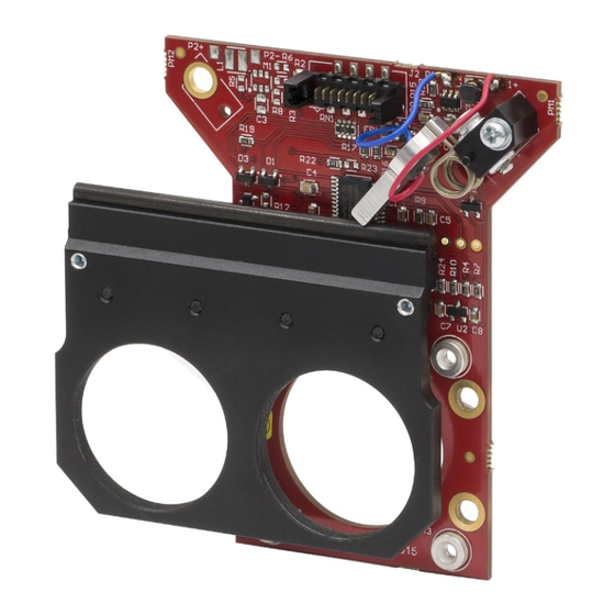
Chapter 1 Introduction The ELL6 dual position slider for SM1 optics is part of the Thorlabs series of piezoelectric resonant motor circuits and bare modules for OEM applications. The resonant piezo design of these motors offers fast response times and precise positioning, and are therefore particularly useful in scanning applications. -
Page 4: Chapter 2 Safety
ELL6K Dual Position Optics Slider Kit Chapter 2: Safety Chapter 2 Safety For the continuing safety of the operators of this equipment, and the protection of the equipment itself, the operator should take note of the Warnings, Cautions and Notes throughout this handbook and, where visible, on the product itself. -
Page 5: Chapter 3 Description
ELL6K Dual Position Optics Slider Kit Chapter 3: Description Chapter 3 Description 3.1. Environmental Conditions Warning Operation outside the following environmental limits may adversely affect operator safety. Location Indoor use only Maximum altitude 2000 m Temperature range 15°C to 40°C Maximum Humidity Less than 80% RH (non-condensing) at 31°C To ensure reliable operation the unit should not be exposed to corrosive agents or excessive moisture, heat or dust. -
Page 6: Mounting
ELL6K Dual Position Optics Slider Kit Chapter 3: Description 3.2. Mounting Warning The safety of any system incorporating this equipment is the responsibility of the person performing the installation. Caution Although the module can tolerate up to 8kV of air discharge, it must be treated as ESD sensitive device. When handling the device, anti-static precautions must be taken and suitable and discharge appliances must be worn. - Page 7 The adapter can also be integrated with Thorlabs' 30 mm Cage System components and/or SM1-threaded components, such as lens tubes. Alternately, 30 mm cage system components alone can be used to mount the sliders. An example of this is shown in Figure 23, in which a CP02 Cage Plate, four ER1 rods, a Ø1/2"...
-
Page 8: Chapter 4 Operation
ELL6K Dual Position Optics Slider Kit Chapter 4: Operation Chapter 4 Operation 4.1. Introduction Caution Although the module can tolerate up to 8kV of air discharge, it must be treated as an ESD sensitive device. When handling the device, anti-static precautions must be taken and suitable and discharge appliances must be worn. Do not expose the slider to a strong infrared light (e.g. -
Page 9: Hand-Held Controller
ELL6K Dual Position Optics Slider Kit Chapter 4: Operation 4.2.1. Hand-held Controller Caution On power up the stage will move while the unit checks the sensors and then searches for the home position. The ELL6K Evaluation Kit also contains a hand-held controller, which features two buttons (marked FW and BW) that allow manual switching between the two slider positions. -
Page 10: Elliptec Software Control
4.2.2. Elliptec Software Control When connected to the host PC, the slider can be controlled remotely, via the Elliptec software. 1. Download the elliptic software from the downloads section at www.thorlabs.com. Double click the saved .exe file and follow the on-screen instructions. -
Page 11: Communications Protocol
ELL6K Dual Position Optics Slider Kit Chapter 4: Operation 4.2.3. Communications Protocol Custom move applications can be written in languages such as C# and C++. The communication bus allows multi-drop communication with speeds at 9600 baud, 8 bit data length, 1 stop bit, no parity. - Page 12 ELL6K Dual Position Optics Slider Kit Chapter 4: Operation Connector J2 Pin Out TYPE FUNCTION Ground ODTX - open drain transmit 3.3V TTL RS232 RX receive - 3.3V TTL RS232 In Motion, open drain active low max 5mA JOG/Mode = normal/test demo, active low max 5V BW Backward , active low max 5V FW Forward, active low max 5V VCC +5V +/-10% 600mA...
-
Page 13: Frequency Search
The ELL6 unit also incorporates a dynamic frequency search. After the initial frequency search detailed above has been performed, the ELL6 unit will search for the best mechanical performance every time the slider is moved, tracking performance against temperature drift and changes of the load value. In this way, the frequency is continually updated. -
Page 14: Periodic Cycling Of Devices Over Full Range Of Travel
ELL6K Dual Position Optics Slider Kit Chapter 4: Operation 4.4. Periodic Cycling of Devices Over Full Range of Travel Caution Periodically, devices should be moved over the full range of travel, from one end to the other. This will help minimize the build up of debris on the track and will prevent the motors digging a groove over the most used area of contact. -
Page 15: Chapter 5 Troubleshooting And Faq
What is the typical product life time ELL6 product life time is restricted by the wearing of moving surfaces and the motor contact as motion is started (due to resonance build up) and performed (due to friction). Therefore, life time is expressed both in km and millions of operations, whichever comes first will depend on the module usage. -
Page 16: Notes On Making A Picoflex Cable For Use When Daisy Chain Devices
ELL6K Dual Position Optics Slider Kit Chapter 5: Troubleshooting and FAQ 5.2. Notes on Making a Picoflex Cable for Use when Daisy Chain Devices The multi-drop communications bus offers the option of connecting the slider to a hybrid network of up to 16 Elliptec resonant motor products and controlling the connected units with a device such as a microprocessor. - Page 17 ELL6K Dual Position Optics Slider Kit Chapter 5: Troubleshooting and FAQ 3. Using a screwdriver or other suitable tool, push down the crimp of each pin to make connection with the ribbon cable. 4. If other connectors are required they should be fitted at this point. Slide each connector onto the cable, paying attention to the orientation as shown below, then crimp as detailed in step (3).
-
Page 18: Chapter 6 Specifications
ELL6K Dual Position Optics Slider Kit Chapter 6: Specifications Chapter 6 Specifications General Specifications Switching Time Unloaded: 180 to 270 ms 100g Load: <600 ms Travel 31 mm (1.22") Endstop Repeatability <100 µm (30 µm Typical) Maximum Load (Vertically Mounted) 150 g (5.29 oz) Minimum Lifetime 100 km (3.3 Million Operations) -
Page 19: Chapter 7 Regulatory
ELL6K Dual Position Optics Slider Kit Chapter 7: Regulatory Chapter 7 Regulatory 7.1. Declarations of Conformity 7.1.1. For Customers in Europe 7.1.2. For Customers In The USA This equipment has been tested and found to comply with the limits for a Class A digital device, persuant to part 15 of the FCC rules. -
Page 20: Chapter 8 Thorlabs Worldwide Contacts
Thorlabs for more information. Waste treatment is your own responsibility. “End of life” units must be returned to Thorlabs or handed to a company specializing in waste recovery. Do not dispose of the unit in a litter bin or at a public waste disposal site. - Page 21 www.thorlabs.com...
Need help?
Do you have a question about the ELL6 and is the answer not in the manual?
Questions and answers