
Related Manuals for THORLABS TED8000 Series


Summary of Contents for THORLABS TED8000 Series
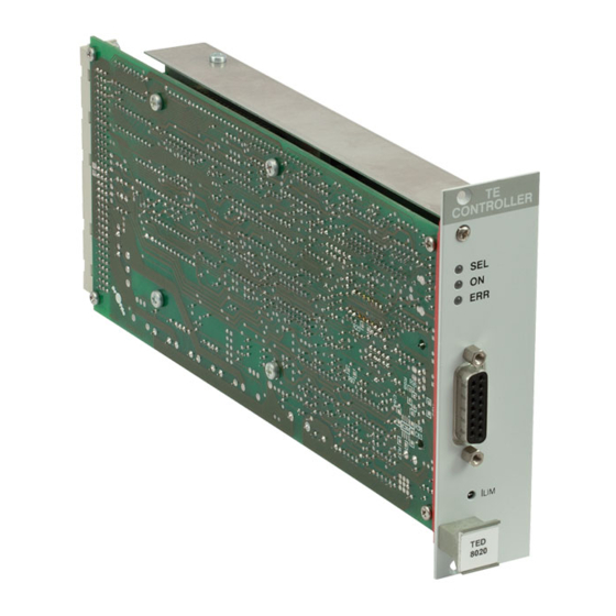
- Page 1 PRO800 / PRO8000 (-4) Series Modular Temperature Controllers TED8000 Operation Manual 2016...
- Page 2 Version: Date: 08-Sep-2016 Item No.: M0009-510-227 Copyright © 2016 Thorlabs...
-
Page 3: Table Of Contents
Contents Foreword 1 General Information 1.1 Safety 1.2 Ordering Codes and Accessories 2 Getting Started 2.1 Parts List 2.2 Operating Principle 2.3 Operating Elements 3 External Connections 3.1 TED80x0 3.2 TED80x0-PT 3.3 TED80x0-KRYO 3.4 Connecting a Thermistor 3.5 Connecting an AD590 3.6 Connecting a LM335 3.7 Connecting a Pt-100 or Pt-1000 3.8 Connecting a TEC Element with Voltage Detector... - Page 4 6.5.10 Device Error Event Enable Register (EDE) 7 Maintenance and Service 7.1 Troubleshooting 8 Appendix 8.1 Technical Data 8.2 Certifications and Compliances 8.3 Literature 8.4 Warranty 8.5 Copyright and Exclusion of Reliability 8.6 Thorlabs 'End of Life' Policy 8.7 List of Acronyms 8.8 Thorlabs Worldwide Contacts...
-
Page 5: Foreword
Paragraphs preceeded by this symbol explain hazards that could damage the instrument and the connected equipment or may cause loss of data. Note This manual also contains "NOTES" and "HINTS" written in this form. Please read these advices carefully! © 2016 Thorlabs... -
Page 6: General Information
Also make sure that your line voltage agrees with the voltage given on the letterplate of the unit and that the right fuse has been inserted! Modules of the TED8000 Series are allowed to be operated only a mainframe of the PRO8000 series. -
Page 7: Ordering Codes And Accessories
1 General Information specified by Thorlabs. The correction of interference caused by such unauthorized modification, substitution or attachment will be the responsibility of the user. The use of shielded I/O cables is required when connecting this equipment to any and all optional peripheral or host devices. -
Page 8: Getting Started
If the shipping container seems to be damaged, keep it until you have inspected the contents and you have inspected the TED8000 mechanically and electrically. Verify that you have received the following items within the package: 1. TED8000 Series Module 2. Operating Manual 2.2 Operating Principle The TED8000 temperature modules are bidirectional current sources to control a TEC element (Peltier). - Page 9 Protection from accidental disabling of the temperature control.. · Separate over-temperature protection for each module Protection against thermal failure of the module. · Laser Protection can be coupled to a temperature window, if TED8000 modules are present within the same PRO8000 mainframe. © 2016 Thorlabs...
-
Page 10: Operating Elements
TED8000 2.3 Operating Elements Note This figure is valid for all TED8000 modules with the exception of the TED8080 which is of double width. © 2016 Thorlabs... -
Page 11: External Connections
The shield must be connected to ground potential (pin 13, 14, 15). For a 4-point measurement of the TEC voltage connect the TEC element to pin 2 and 9 to measure the voltage directly at the TEC element. © 2016 Thorlabs... -
Page 12: Ted80X0-Pt
The shield must be connected to ground potential (pin 13, 14, 15). For a 4-point measurement of the TEC voltage connect the TEC element to pin 2 and 9 to measure the voltage directly at the TEC element. © 2016 Thorlabs... -
Page 13: Ted80X0-Kryo
The shield must be connected to ground potential (pin 13, 14, 15). For a 4-point measurement of the TEC voltage connect the TEC element to pin 2 and 9 to measure the voltage directly at the TEC element. © 2016 Thorlabs... -
Page 14: Connecting A Thermistor
(pins 3 and 4) via a 1 kW resistor. Therefore the following behavior can be expected in case of a faulty sensor or missing connection: · No sensor connected: Error message „No Sensor“; the display shows the upper range limit for actual resistance or actual temperature. The output cannot be activated. © 2016 Thorlabs... -
Page 15: Connecting A Tec Element With Voltage Detector
4-pole Measurement of the TEC Voltage Attention An reverse poled TEC element may lead to a thermal runaway and destruction of the connected components. Please refer to section Polarity Check of the TEC Element © 2016 Thorlabs... -
Page 16: Polarity Check Of The Tec Element
P-, I- and D-share of the control loop may still need improvement. 3.10 Connecting the Status Display LED To display the operating status a standard LED may be used between pin 1 and pin 8. The LED will light up when the current output is switched on. © 2016 Thorlabs... -
Page 17: Optimization Of Temperature Control
3. The transient response after setting a new temperature is limited since the heat transport in the copper block is relatively slow. Furthermore, the sensor must settle to the laser temperature - it also has a non-negligible thermal capacity. Possible optimization: careful adjustment of PID parameters © 2016 Thorlabs... -
Page 18: Pid Adjustment
· Change the set temperature repeatedly between 18 °C and 22 °C . · Increase the I-share gradually. Higher values will accelerate the settling to the set temperature. The I-share is set correctly when the actual temperature reaches the set temperature in shortest time without overshoots. © 2016 Thorlabs... -
Page 19: Operating Instruction
TED8000 module via the D/A converter. It yields exactly the same protective function as the hardware limit. See section Changing Parameters Note The TEC current limitation is enabled at the lower value of the two limits I or I © 2016 Thorlabs... -
Page 20: Functions In The Main Menu
Select a module for further input by setting the cursor to the channel number of the desired module using the soft keys Pressing will lead to the channel menu Setting the temperature To set the set temperature in the main menu, select the corresponding module (here CH2) with the cursor: © 2016 Thorlabs... - Page 21 Now, the set temperature can be adjusted by means of the tuning knob. Pressing the completes the procedure. Note If the TEC current is switched ON, the actual temperature is displayed. In this case the set temperature can still be changed but is not displayed. © 2016 Thorlabs...
-
Page 22: Functions In The Channel Menu
If the sensor is a Pt-100 (Pt-100 option) Kry hi If the sensor is a Pt-1000 (200 to 500 W; KRYO module only) Kry lo If the sensor is a Pt-1000 (480 to 1200 W; KRYO module only) © 2016 Thorlabs... - Page 23 RA = 9.1234 kW Rwin= 6.1234kW R0= 10.000 kW B = 3900.0 T0= 25.000 °C C1= 1.1234E-3 C2= 2.1234E-4 C3= 3.1234E-6 PT100 Rs=100.00 W Ra=100.25 W Rwin=10.50 W KRYO low range Rs=300.00 W Ra=298.45 W Rwin=10.50 W AD590 AD590 © 2016 Thorlabs...
-
Page 24: Changing Parameters
The sensor type can be selected in the TED80xx modules by selecting the line "Thermistor" respectively "AD590". AD590 = AD590 and LM335 families Thermistor = Thermistor. Please select the corresponding range (HI or LO). The channel menu displays in the second line the options: AD590 Th lo Th hi © 2016 Thorlabs... -
Page 25: Selecting The Thermistor Range
Low range High In “ “, the operating temperature range is 76 K to about 148 K, in the “ range “ - from 143 K to about 325 K. The display changes between: Low range High range © 2016 Thorlabs... -
Page 26: Thermistor Calibration
C1, C2 and C3. To change the three parameters in accordance with the actual thermistor, select them one by one and set them to the desired value. Pressing terminates the input and applies value. © 2016 Thorlabs... -
Page 27: 1000 Calibration (Kryo Only)
Please keep in mind that if you use the TED8000 module in conjunction with a LDC8xxx laser diode controller, the LDC might switch off the laser current automatically when changing the temperature window, as the actual laser temperature could be outside the new window. © 2016 Thorlabs... -
Page 28: Setting The P, I And D Share Of The Control Loop
. The LED “SEL” of the selected module lights up. Press the key to switch on the selected module. The LED “ON” of the selected module will light up, this way indicating that the TEC current is enabled. © 2016 Thorlabs... -
Page 29: Error Messages
If the error occurs when trying to switch on, it is displayed in cursor arrows: }CH1 No Sensor| Any error must be confirmed by pushing the " " soft key. Any further operation is locked until " " soft key is pushed. © 2016 Thorlabs... -
Page 30: Communication With A Pc
, section 8.7.3) Numeric response data Type 3 (<NR3>) is a numerical value with or without sign in floating point notation with exponent with sign. 1.1E+1 or +1.1E-1 or -22.1E+1 or 143.56789432E+306 Examples: (See IEE488.2 , section 8.7.4) © 2016 Thorlabs... -
Page 31: Commands And Queries
[:CALTB:MAX <NR3><LF>] ":CALTR:MAX?" Reads the maximum allowed nominal resistance R [:CALTR:MAX <NR3><LF>] ":CALTT:MAX?" Reads the maximum allowed nominal temperature T [:CALTT:MAX <NR3><LF>] Refer to section Thermistor Calibration - Exponential Method Attention These commands do not apply to TED8000-KRYO! © 2016 Thorlabs... -
Page 32: Thermistor Calibration - Steinhart-Hart Method
The selection by which method (exponential or Steinhart-Hart) the sensor calibration will be executed, depends on the order in which the coefficients are transmitted: · If the last transmitted calibration command belongs to the exponential method (see above), then the calculation is also done with the exponential method. © 2016 Thorlabs... -
Page 33: Switching The I Share On / Off (Integ)
Reads the maximum TEC current for I - ADC = FFFF ":ITE:MAX_R?" [:ITE:MAX_R <NR3><LF>] Reads the position of the TEC current as measurement value in ":ITE:MEAS?" the “ELCH” output string (1..8, 0 if not selected) [:ITE:MEAS <NR1><LF>] ) ELectrical CHaracterization © 2016 Thorlabs... -
Page 34: Programming The Tec Current Software Limit (Limt)
Reading Reads the actual TEC hardware current limit ":LIMTP:ACT?" [:LIMTP:ACT <NR3><LF>] Reads I - DAC = 0000 ":LIMT:MIN_W?" TE MAX [:LIMT:MIN_W <NR3><LF>] Reads I - DAC = FFFF ":LIMT:MAX_W?" TE MAX [:LIMT:MAX_W <NR3><LF>] See also section Pre-Settings © 2016 Thorlabs... -
Page 35: Programming The Resistance Of The Temperature Sensor (Resi)
Reads R - ADC = 0000 ":RESI:MIN_R?" [:RESI:MIN_R <NR3><LF>] Reads R - ADC = FFFF ":RESI:MAX_R?" [:RESI:MAX_R <NR3><LF>] Reads the position of R as measurement value in the “ELCH” ":RESI:MEAS?" output string (1..8, 0 if not selected) [:RESI:MEAS <NR1><LF>] ) ELectrical CHaracterization © 2016 Thorlabs... -
Page 36: Programming The Resistance Window (Rwin)
Sensor: Pt-1000, low temperature range ":SENS PT1000H" Sensor: Pt-1000, high temperature range Reading Reads the actual sensor type ":SENS?" [:SENS AD<LF>] [:SENS THL<LF>] [:SENS THH<LF>] [:SENS PT100<LF>] [:SENS PT1000L<LF>] [:SENS PT1000H<LF>] ) Only for TED8000-PT ) Only for TED8000-KRYO © 2016 Thorlabs... -
Page 37: Programming The Pid Shares (Sharep, Sharei, Shared)
6.3.12 Switching the TEC On / Off (TEC) Command Explanation Response Example Programming Switches the TEC output ON ":TEC ON" Switches the TEC output OFF ":TEC OFF" Reading Reads the TEC output status: ":TEC?" [:TEC ON<LF>] [:TEC OFF<LF>] © 2016 Thorlabs... -
Page 38: Programming The Temperature (Temp)
Reads T - ADC = 0000 ":TEMP:MIN_R?" [:TEMP:MIN_R <NR3><LF>] Reads T - ADC = FFFF ":TEMP:MAX_R?" [:TEMP:MAX_R <NR3><LF>] ":TEMP:MEAS?" Reads the position of TEMP as measurement value in the “ELCH” output string (1..8, 0 if not selected) [:TEMP:MEAS <NR1><LF>] ) ELectrical CHaracterization © 2016 Thorlabs... -
Page 39: Programming The Temperature Window (Twin)
Response Example Reading Reads the module ID (here 223 for TED8000) ":TYPE:ID?" [:TYPE: 223<LF>] Queries the module's sub-type: ":TYPE:SUB?" [:TYPE:SUB <NR1><LF>] where the <NR1> value stands for: 0 = Standard TED8000 1 = TED8000-PT 2 = TED8000-KRYO © 2016 Thorlabs... -
Page 40: Reading The Tec Voltage (Vte)
":VTE:MAX_R?" Reads the maximum U - ADC = FFFF [:VTE:MAX_R <NR3><LF>] Reads the position of the TEC voltage as measurement value in ":VTE:MEAS?" the “ELCH” output string (1..8, 0 if not selected) [:VTE:MEAS <NR1><LF>] ) ELectrical CHaracterization © 2016 Thorlabs... -
Page 41: Ieee Error Messages
PRO8000 mainframe ESR Standard event status register Standard event Status Enable Register Status Byte Register Service Request Enable Register to program various service request functions and status reporting. See also IEE488.2 Standard , section 11. © 2016 Thorlabs... - Page 42 TED8000 Structure of the registers DEC, DEE and EDE © 2016 Thorlabs...
- Page 43 6 Communication with a PC Structure of the registers ESR, ESE, STB and SRE © 2016 Thorlabs...
-
Page 44: Standard Event Status Register (Esr)
This bit is HIGH, after a command has finished and all bits of the STB have been set. All bits except bit 6 of the STB can be used to assert a service request (SRQ ). Alternatively the "*STB?" SRQ can be recognized using the command or by serial poll © 2016 Thorlabs... -
Page 45: Service Request Enable Register (Sre)
A temperature sensor could not be recognized, or the type of the recognized sensor does not match the setting of the TED8000. Bit 8 - Power supply error Internal power supply error. The DEC can be read but not set. Reading does not clear the DEC. © 2016 Thorlabs... -
Page 46: Device Error Event Register (Dee)
"OR" so that any "hit" leads to a logical 1 in bit 3 (DES) of the STB. As any bit of the STB can assert an SRQ, every error (bit of the DEE) can be used to assert an SRQ. © 2016 Thorlabs... -
Page 47: Maintenance And Service
Thorlabs for return instructions. Do not remove covers! In order to ensure best performance, accuracy and reliable operation, Thorlabs recommends a recalibration after 24 months. 7.1 Troubleshooting In the case that your TED8000 shows malfunction please check the following topics: u The module does not work at all (no display on the mainframe): Ø... - Page 48 Thermistor Calibration Ø Is the PID loop set up correctly? § Verify the PID share adjustment, see section PID Adjustment If above hints could not resolve the malfunction, please contact Thorlabs for technical support and/or return instructions. © 2016 Thorlabs...
-
Page 49: Appendix
Resistance Stability (24h, typ.) < 0.5 W / 5 W Thermistor (Calibrated, Temperature Display in °C) Measurement Current 100 µA / 10 µA Control Range Temperature at 20 kW / 200 kW to 150 °C Resolution Setting Accuracy © 2016 Thorlabs... - Page 50 ) Depending on the Selected Range (20 kW / 200 kW) ) Depending on Thermistor Specification ) Depending on Selected Range (High / Low) ) After Applying Correction Factors as Stated in Section Pt-1000 Calibration (KRYO only) © 2016 Thorlabs...
-
Page 51: Certifications And Compliances
TEC OUT port. Compliance demonstrated w ith the TED8000 Series modules installed in the Thorlabs PRO8xxx Series Mainframes. Emissions, w hich exceed the levels required by these standards, may occur w hen this equipment is connected to a test object. -
Page 52: Literature
TED8000 8.3 Literature IEEE488.2-1992 - IEEE Standard Codes, Formats, Protocols, and Common Commands for Use With IEEE Std 488.1-1987, IEEE Standard Digital Interface for Programmable Instrumentation Available at http://www.ieee.org/publications_standards/index.html © 2016 Thorlabs... -
Page 53: Warranty
For warranty repairs or service the unit must be sent back to Thorlabs. The customer will carry the shipping costs to Thorlabs, in case of warranty repairs Thorlabs will carry the shipping costs back to the customer. -
Page 54: Copyright And Exclusion Of Reliability
Thorlabs dealer or system installer. All rights reserved. This document may not be reproduced, transmitted or translated to another language, either as a whole or in parts, without the prior written permission of Thorlabs. Copyright © Thorlabs 2016. All rights reserved. -
Page 55: Thorlabs 'End Of Life' Policy
Waste treatment on your own responsibility If you do not return an “end of life” unit to Thorlabs, you must hand it to a company specialized in waste recovery. Do not dispose of the unit in a litter bin or at a public waste disposal site. -
Page 56: List Of Acronyms
Laser Diode Laser Diode Controller Light Emitting Diode Line Feed Local Lockout Laser Source Module Numeric Response data of type 1 Numeric Response data of type 2 Numeric Response data of type 3 Message AVailable Master Summary Status © 2016 Thorlabs... - Page 57 8 Appendix Over Temperature Protection Personal Computer Photo Diode ReQuest Service Message Selected Device Clear SELect Service Request Enable Register Service ReQuest STatus Byte Register Soft Ware ThermoElectric Cooler (Peltier Element) TRiGger © 2016 Thorlabs...
-
Page 58: Thorlabs Worldwide Contacts
Email: europe@thorlabs.com Email: scandinavia@thorlabs.com France Brazil Thorlabs SAS Thorlabs Vendas de Fotônicos Ltda. 109, rue des Côtes Rua Riachuelo, 171 78600 Maisons-Laffitte São Carlos, SP 13560-110 France Brazil Tel: +33-970 444 844 Tel: +55-16-3413 7062 Fax: +33-811 38 17 48 Fax: +55-16-3413 7064 www.thorlabs.com... - Page 60 www.thorlabs.com...
Need help?
Do you have a question about the TED8000 Series and is the answer not in the manual?
Questions and answers