Table of Contents
Advertisement
Quick Links
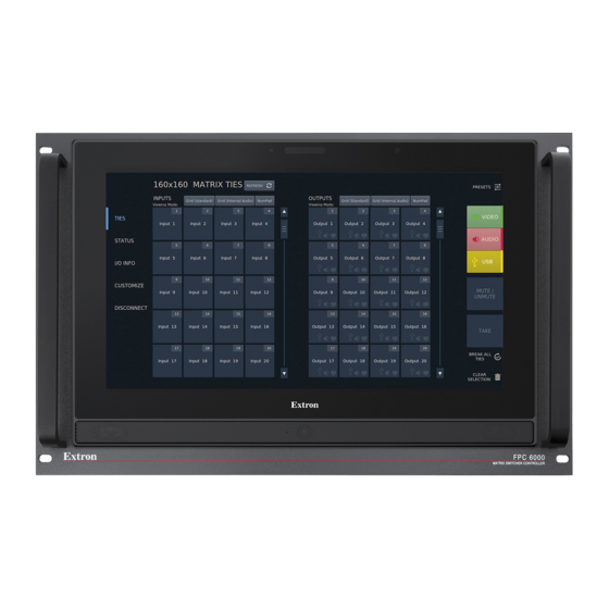
FPC 6000
Front Panel Controller
I/O INFORMATION
RE FRE S H
IN PU T
Grid (Standard)
Numpad
Viewing Mode:
13
14
15
16
T I E S
Input 13
Input 14
Input 15
Input 16
S TAT U S
17
18
19
20
Input 17
Input 18
Input 19
Input 20
I /O I N F O
21
22
23
24
C U S TO M I Z E
Input 21
Input 22
Input 23
Input 24
D I S C O N N E C T
25
26
27
28
Input 25
Input 26
Input 27
Input 28
29
30
31
32
Input 29
Input 30
Input 31
Input 32
User Guide
Matrix Switcher Accessories
Selected Input:
3 1
I n p u t 3 1
SFP Module Status
FINI
Outputs
Board Config Type
Slot 4, Non-reclocking Singlem
Laser Status
1 (Enable)
Re-clocker status
5 (10.0 Gbps)
Tied Outputs:
1
O u t p u t 1
2
O u t p u t 2
3
O u t p u t 3
4
O u t p u t 4
5
O u t p u t 5
O u t p u t 6
6
O u t p u t 7
7
O u t p u t 8
8
9
O u t p u t 9
FPC 6000
MATRIX SWITCHER CONTROLLER
Inputs
68-3259-01 Rev. D
01 21
Advertisement
Table of Contents

Related Manuals for Extron electronics FPC 6000


Summary of Contents for Extron electronics FPC 6000
- Page 1 User Guide Matrix Switcher Accessories FPC 6000 Front Panel Controller I/O INFORMATION RE FRE S H IN PU T Grid (Standard) Numpad Viewing Mode: Selected Input: I n p u t 3 1 Inputs T I E S Input 13...
- Page 2 Safety Instructions Safety Instructions • English Istruzioni di sicurezza • Italiano AVVERTENZA: Il simbolo, , se usato sul prodotto, serve ad WARNING: This symbol, ,when used on the product, is avvertire l’utente della presenza di tensione non isolata pericolosa intended to alert the user of the presence of uninsulated dangerous all’interno del contenitore del prodotto che può...
- Page 3 安全記事 • 繁體中文 안전 지침 • 한국어 警告 경고: 이 기호 가 제품에 사용될 경우, 제품의 인클로저 내에 있는 若產品 上使 用此 符 號 , 是 為了提 醒 使 用者,產品 機 殼內 存 在 著 可能會導致觸電之風險的未絕緣危險電壓。 접지되지 않은 위험한 전류로 인해 사용자가 감전될 위험이 있음을 경고합니다.
- Page 4 FCC Class A Notice This equipment has been tested and found to comply with the limits for a Class A digital device, pursuant to part 15 of the FCC rules. The Class A limits provide reasonable protection against harmful interference when the equipment is operated in a commercial environment. This equipment generates, uses, and can radiate radio frequency energy and, if not installed and used in accordance with the instruction manual, may cause harmful interference to radio communications.
- Page 5 Conventions Used in this Guide Notifications In this user guide, the following are used: WARNING: Potential risk of severe injury or death. AVERTISSEMENT : Risque potentiel de blessure grave ou de mort. CAUTION: Risk of minor personal injury. ATTENTION : Risque de blessure mineure.
-
Page 7: Table Of Contents
Take ..............26 Break ..............26 Mounting ..............6 Clear Selection ..........26 Create a Tie ............27 Installing the FPC 6000 in a Rack or Control Break A Tie ............28 Console ..............6 Presets .............30 Underwriters Laboratories (UL) Guidelines for Status Screen ............34 Rack Mounting ............7 I/O Info Screen ............34... - Page 8 FPC 6000 • Contents viii...
-
Page 9: Introduction
The FPC 6000 uses an Extron TLP Pro 1520M TouchLink touchscreen to provide an intuitive, 15-inch control interface with straightforward menus for quick and easy system configuration. The FPC 6000 is a stand-alone device that does not require an additional external controller or configuration with Global Configurator Plus and Professional or GUI Designer software. -
Page 10: Application Diagram
PRIMARY REDUNDANT 100-240V --A MAX 100-240V --A MAX PRIMARY PRIMARY 50-60 Hz FOX3 MATRIX 320x 50-60 Hz Ethernet AV Control Network Ethernet FPC 6000 MATRIX SWITCHER CONTROLLER Extron FPC 6000 Figure 1. FPC 6000 Application Diagram FPC 6000 • Introduction... -
Page 11: Matrix Switcher Terms
NOTE: The number of rooms and presets that are available depends on the matrix switcher that is connected to the FPC 6000. See the user guide for the matrix switcher at www.extron.com for further information. -
Page 12: Installation Overview
… power injector and connect the power injector to the Ethernet LAN (see figure 6 page 11). If you are using a 12 VDC power supply (not provided), connect the FPC 6000 directly … to the LAN (see XTP/LAN/PoE input on page 11) and connect the power supply to FPC 6000. - Page 13 Use the Setup Menu (see page 13) to set the DHCP status and, if required, the IP … address, subnet mask, gateway, and related settings for the FPC 6000. Test the connection to the switcher. … FPC 6000 • Installation Overview...
-
Page 14: Mounting
Mounting When the FPC 6000 ships, it is housed in a 7U high, 19 inch wide, rack-mountable panel that can be installed in any standard equipment rack or control console. Follow the instructions below and read the Underwriters Laboratories (UL) Guidelines for Rack Mounting on the next page. -
Page 15: Underwriters Laboratories (Ul) Guidelines For Rack Mounting
(such as the use of power strips). Wall Mounting the FPC 6000 The FPC 6000 can also be wall-mounted, either using the Extron BB 700M wall box or directly into drywall. Some local building codes require the touchpanel to be mounted in a wall box. To use the BB 700M, see the TLP Pro 1220MG, TLP Pro 1520MG, and TLP Pro 1720MG Setup Guide, at www.extron.com. - Page 16 The size of the cut-out hole is 8.90 inches (22.61 cm) wide x 5.70 inches (14.48 cm) high. The FPC 6000 ships, already mounted, in a rackmountable metal panel. Remove the FPC 6000, and unscrew the mounting plate from the panel.
-
Page 17: Panel Features
Rear Panel Features • Front Panel Features Figure 4 shows the front panel of the FPC 6000, removed from the mounting frame. Figure 4. FPC 6000 Front Panel Communication LED — Lights briefly when the unit boots up. Otherwise, this LED has no function on the FPC 6000. -
Page 18: Rear Panel Features
Rear Panel Features Figure 5 shows the rear panel of the FPC 6000, removed from the mounting frame. NOTE: The ports marked , and have no function in the FPC 6000, and are covered with black plastic strips. RESET HDMI IN... - Page 19 • directly to the network using a twisted pair cable, terminated with an RJ-45 connector. PoE Input — If you use the provided PoE power injector, connect the FPC 6000 to the • power injector output and connect the power injector input to the LAN.
- Page 20 5 on page 10). Mounting Notches — Used to attach the mounting plate to the FPC 6000 12 VDC Power Supply Input — If you are not using Power over Ethernet, connect a 12 VDC, 3.0 A power supply to this captive screw connector. The power supply must be purchased separately.
-
Page 21: Setup Menu
To open the setup menu, press the Settings link at the bottom of the Login screen (see figure 20 on page 22), which appears when the FPC 6000 is powered on. Alternatively, press one of the buttons, which are found on the rear panel (see... -
Page 22: Network
The right and left arrows move the cursor inside the Host Name text box. • Click the Shift key to toggle between upper and lower case letters. • Press Enter to save the new name. • FPC 6000 • Setup Menu... - Page 23 Press Apply to apply the new values or press 0.0.0.10 Revert to return to the previous values without saving the changes. The button returns to gray. If you have not made any changes, the Apply and Revert buttons are grayed out. FPC 6000 • Setup Menu...
-
Page 24: Display
If Wake on Motion has not been set and the screen is in sleep mode, touch the screen • to restore it to an active state. FPC 6000 • Setup Menu... -
Page 25: Audio
Advanced Screen Figure 13. Menu PIN The PIN setup options allow you to enable, disable, or change the setup menu PIN. The PIN is a four-digit number. Each digit can have any value from 0-9. FPC 6000 • Setup Menu... - Page 26 The title bar changes to Confirm New Menu Pin. Enter the PIN a second time. When the PIN entered on the second occasion matches the PIN entered on the first occasion, the PIN is set and the dialog closes. FPC 6000 • Setup Menu...
-
Page 27: Fpc 6000 Web Page
FPC 6000 Web Page To access the FPC 6000 embedded web page, enter the IP address of the unit into the web browser of a PC connected to the same subnet. A dialog box opens asking for your user name... -
Page 28: Updating The Firmware
Updating the Firmware Firmware for the FPC 6000 can be upgraded using the touchpanel web page. Before starting, consult your IT team and ensure that the touchpanel has a unique IP address. Downloading Firmware Power on a computer that is connected to the same network as the touchpanel. -
Page 29: Updating Firmware Using The Touchpanel Web Page
Figure 19. Popup Screens from Firmware Update When the update is complete, the FPC 6000 reboots and the login screen is shown. You need to log in to the controller once again (see Login Screen on page 22). -
Page 30: Operation
Operation The FPC 6000 is a touchscreen interface that allows the user to control, monitor, access, and manage a range of Extron matrix switchers via a direct connection or over a local area network. Two or more FPC units connected to the network allow the matrix switcher to be controlled from multiple locations. - Page 31 To change the password, you must use the Extron Toolbelt utility (see the Toolbelt Help File). Talk to your Extron rep about obtaining a license for Toolbelt. Press Submit. The FPC 6000 attempts to connect to the matrix switcher. If successful, the Ties Screen appears (see figure 23 on the next page).
-
Page 32: Ties Screen
If the FPC 6000 cannot connect to the matrix switcher, an error message appears: Extron Login There was an error connecting to the Matrix No Response Matrix IP Address Port Password DISCONNECT CONNECT FPC IP: 192.168.254.251 FPC Settings Figure 22. -
Page 33: Menu Buttons
Simple Instruction Set (SIS) commands (see the matrix switcher user guide for instructions) and through the PCS. The FPC 6000 screen shows 20 inputs at a time. Use the scroll bar to the right of the inputs to navigate through all the inputs that are available with your matrix switcher. -
Page 34: Audio Button
Clear Selection Ties created on this screen do not go into effect until they are saved by pressing Take. To undo ties before they have been saved, press the Clear Selection button ( FPC 6000 • Operation... -
Page 35: Create A Tie
Figure 28. In figure 28 a potential tie has been created between Input 186 and Output 115. NOTE: You can also tie an input to all outputs by pressing the Select All button (see page 29). FPC 6000 • Operation... -
Page 36: Break A Tie
Input 193 Input 194 Input 195 Input 196 TAKE Input 197 Input 198 Input 199 Input 200 Output 125 Output 126 Output 127 Output 128 SELECT AL L CLEAR SELECT IO N Breaking a Tie Figure 30. FPC 6000 • Operation... - Page 37 Press Break to break the ties or CANCEL to keep the ties. The Break button counts down in seconds. If neither button is pressed after 10 seconds, the request is cancelled and the ties are broken. FPC 6000 • Operation...
-
Page 38: Presets
They are grouped together for the convenience of the operator. Rooms and room presets can be recalled but cannot be created with the FPC 6000. They must be created by SIS commands sent from a PC to the switcher (see the user guide for your matrix switcher). - Page 39 Select one of the presets that has already been named and saved. Press Save Preset. A warning dialog box appears: Figure 34. Overwrite Warning Dialog Press Save Preset to save or CANCEL to exit without saving. FPC 6000 • Operation...
- Page 40 PRESETS Recall from... Save As... Figure 35. FPC 6000 Presets Menu Press Recall from [...]. The RECALLING PRESET menu opens as a sidebar on the right of the screen with the global presets listed. If required, press the Global tab (it is usually selected by default; figure 37,...
- Page 41 The progress bar (see figure 29 on page 28) appears with the message Global Preset X. NNN Successfully Recalled, where X is the number of the Global preset and NNN is the name assigned to the preset. FPC 6000 • Operation...
-
Page 42: Status Screen
O u t p u t 9 Figure 40. FPC 6000 I/O Info Screen (Inputs) The inputs are organized in the same way that they are in the Ties screen. From this screen, you can select an input by pressing an input button. When you press an input button, details about that input appear on the right side of the screen. -
Page 43: Customize Screen
Medium Theme • Light Theme • Press the desired option. The selected option is highlighted in blue. Press Save Changes to save the selection. The FPC 6000 may take a few moments to update the screen view. FPC 6000 • Operation... -
Page 44: Reset Modes
The login screen opens with the message Project Not Running. The FPC 6000 cannot be accessed from the front panel. The FPC 6000 IP address has not been changed. Use a PC to open the FPC 6000 web page and reinstall the latest firmware (see Updating Firmware Using the Touchpanel Web Page). -
Page 45: Reset All Ip Settings
Setup menu (see page 14) to reset the IP address. Once the IP address has been reset, use a PC to open the FPC 6000 web page and reinstall the latest firmware (see Updating Firmware Using the Touchpanel Web Page on page 21). - Page 46 (see page 14) to reset the IP address. Setup Once the IP address has been reset, use a PC to open the FPC 6000 web page and reinstall the latest firmware (see Updating Firmware Using the Touchpanel Web Page on page 21).
- Page 47 Extron Warranty Extron warrants this product against defects in materials and workmanship for a period of three years from the date of purchase. In the event of malfunction during the warranty period attributable directly to faulty workmanship and/ or materials, Extron will, at its option, repair or replace said products or components, to whatever extent it shall deem necessary to restore said product to proper operating condition, provided that it is returned within the warranty period, with proof of purchase and description of malfunction to: USA, Canada, South America,...
Need help?
Do you have a question about the FPC 6000 and is the answer not in the manual?
Questions and answers