Table of Contents
Advertisement
Quick Links
HD CTL 100 Workspace Controller • Setup Guide
The Extron HD CTL 100 is a compact workspace controller designed for automatic display control in small meeting rooms and
huddle spaces. It features an HDMI pass-through port that detects signal presence and can facilitate automatic display power.
When an active signal is connected to the HDMI input, the HD CTL 100 automatically turns on the display via CEC control. When
no signal is detected, the HD CTL 100 powers off the display after a predetermined period. For further flexibility, integration with
Extron OCS 100 occupancy sensors can enable the controller to power the display on when users enter the room. Control of the
display is provided via one-way RS-232, IR, or Consumer Electronics Control (CEC).
NOTE:
For more details about installation, configuration, and operation, see the HD CTL 100 User Guide, available at
www.extron.com.
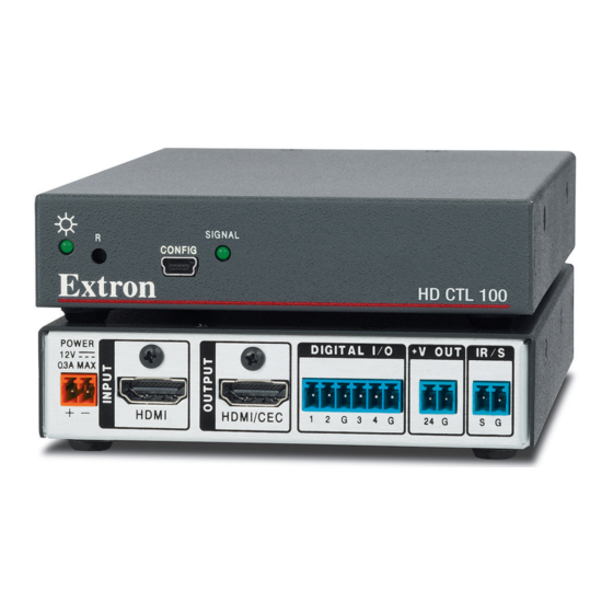
HD CTL 100 Panels
The front and rear panel connectors include:
Rear Panel
POWER
12V
0.3A MAX
HDMI
HDMI/CEC
A A
B B
C C
Power input connector
A
HDMI input connector
B
HDMI output connector
C
Digital I/O ports
D
Figure 1.
HD CTL 100 Rear and Front Panels
Installation Steps
ATTENTION:
•
Installation and service must be performed by authorized
personnel only.
•
L'installation et l'entretien doivent être effectués uniquement par
un technicien qualifié.
(Optional) Mount the HD CTL 100 on a wall, rack, rack shelf, or furniture.
1.
Mounting kits are available at www.extron.com.
TIP:
Extron recommends wall-mounting the HD CTL 100 behind
the display (place the top panel of the unit against the wall).
using a mounting kit such as the Extron MBU 125 Under Desk
Mounting Brackets (see the illustration at right). Mounting kits
and instructions are available at www.extron.com.
Wire and connect the provided power supply to the
2.
two-pole rear panel Power connector (see figure 1,
and the illustration at right).
Connect an HDMI source to the INPUT connector (see
3.
figure 1,
).
B
Connect an HDMI display or other output device to the
4.
rear panel OUTPUT connector (see figure 1,
DIGITAL I / O
+V OUT
IR / S
1
2
G
3
4
G
24
G
S G
D D
E E
F F
Voltage output connector
E
IR/S control connector
F
USB configuration port
G
A
,
).
C
J
I I
SIGNAL
R
CONFIG
G G H H
Signal LED
H
Reset button
I
Power LED
J
Ground all devices.
External
Power Supply
(0.5 A, 12 VDC)
Front Panel
HD CTL 100
POWER
12V
0.3A MAX
12 VDC Input
Ground
1
HDMI
HDMI
Advertisement
Table of Contents

Related Manuals for Extron electronics HD CTL 100


Summary of Contents for Extron electronics HD CTL 100
- Page 1 It features an HDMI pass-through port that detects signal presence and can facilitate automatic display power. When an active signal is connected to the HDMI input, the HD CTL 100 automatically turns on the display via CEC control. When no signal is detected, the HD CTL 100 powers off the display after a predetermined period.
- Page 2 Each port can be configured as a digital input, output, input with pull-up, or output with pull-up, via the HD CTL 100 Configuration Program. The ports enable you to monitor connected devices and trigger functions on the controller.
- Page 3 Starting the Configuration Program To use the HD CTL 100 to control devices, you must create one or more configurations for it, using the HD CTL 100 Configuration Program. A configuration is a set of specifications for command assignments and port parameters that enable the HD CTL 100 to control your display device.
- Page 4 HD CTL 100 • Setup Guide (Continued) An HD CTL 100 project is a file (with a .hdc extension) that contains port configurations for one or more HD CTL 100s. A configuration must be created within a new or existing project. A project can be saved, copied, and edited (for example, by adding or changing configurations within it).
Need help?
Do you have a question about the HD CTL 100 and is the answer not in the manual?
Questions and answers