
Related Manuals for Extron electronics MediaLink MLC Plus 84 Series


Summary of Contents for Extron electronics MediaLink MLC Plus 84 Series
- Page 1 User Guide MediaLink Products ® MLC Plus 84 Series MediaLink Controllers 68-2346-01 Rev. E 01 19...
- Page 2 Safety Instructions Safety Instructions • English Istruzioni di sicurezza • Italiano AVVERTENZA: Il simbolo, , se usato sul prodotto, serve ad WARNING: This symbol, ,when used on the product, is avvertire l’utente della presenza di tensione non isolata pericolosa intended to alert the user of the presence of uninsulated dangerous all’interno del contenitore del prodotto che può...
- Page 3 All trademarks mentioned in this guide are the properties of their respective owners. The following registered trademarks , registered service marks , and trademarks are the property of RGB Systems, Inc. or Extron Electronics (®) (SM) (™) (see the current list of trademarks on the Terms of Use page at www.extron.com):...
- Page 4 FCC Class A Notice This equipment has been tested and found to comply with the limits for a Class A digital device, pursuant to part 15 of the FCC rules. The Class A limits provide reasonable protection against harmful interference when the equipment is operated in a commercial environment.
- Page 5 Conventions Used in this Guide Notifications The following notifications are used in this guide: CAUTION: Risk of minor personal injury. ATTENTION : Risque de blessure mineure. ATTENTION: • Risk of property damage. • Risque de dommages matériels. NOTE: A note draws attention to important information. TIP: A tip provides a suggestion to make working with the application easier.
-
Page 7: Table Of Contents
Contents Introduction Mounting ............28 ........... 1 Mounting the MLC Plus 84 D ......28 Before You Begin ..........1 Mounting the MLC Plus 84 EU or What This Guide Covers ......... 1 MLC Plus 84 MK ......... 29 Conventions Used in This Guide ..... 1 Important Information You Need Before Operation Installation ............. - Page 8 Maintenance Index ..........46 ............. 49 Removing the MLC Plus EU or MK from the Mounting Surface ..........46 Firmware Updates ..........47 Determining the Firmware Version ....47 Updating the Firmware ......... 48 MLC Plus 84 Series • Contents...
-
Page 9: Introduction
Introduction This section covers the following basic information you should know about this guide and the product before installation: • Before You Begin • About the MLC Plus 84 Series • Application Diagrams • Device Control About Global Configurator (with GC Professional and GC Plus Modes)PC •... -
Page 10: About The Mlc Plus 84 Series
About the MLC Plus 84 Series The MLC Plus 84 Series Controllers integrate Ethernet connection into AV systems to allow users to remotely control, monitor, and troubleshoot AV equipment. This equipment includes but is not limited to display devices, switchers, source devices, and various other items such as lights, a projector lift, or a screen motor. They can be used in a distributed control system environment or as stand-alone controllers. -
Page 11: Features
Once you have set up how you want it to work (set up IP addresses and functions, assigned drivers to ports, configured relays and digital input), that information is saved to a project configuration file that is built and uploaded into the MLC Plus. The MLC Plus 84 Series integrates seamlessly with Extron GlobalViewer Enterprise (GVE) software and Extron Control apps for remote control applications. -
Page 12: Application Diagrams
• E-mail notification — The MLC can be set up to send e-mail notifications, such as a notice that a projector has been disconnected or the projector lamp has been used for a designated number of hours. Application Diagrams The following figure shows an example of types of devices that can be connected to ports on the MLC Plus 84 Series controllers. -
Page 13: About Global Configurator (With Gc Professional And Gc Plus Modes)
About Global Configurator (with GC Professional and GC Plus Modes) Use Extron Toolbelt software to discover and manage the MLC Plus Series controller and other Extron control products. Configure the controller using Extron Global Configurator software running in Global Configurator Professional (GC Professional) or Global Configurator Plus (GC Plus) mode. -
Page 14: Hardware Features And Installation
Hardware Features and Installation This section covers the following material: • Overall Configuration Procedure for the Controller — A flowchart showing the main steps needed to install and set up the controller • Installation Step 1: Get Ready — A checklist of tasks to guide you through installation •... -
Page 15: Overall Configuration Procedure For The Controller
Overall Configuration Procedure for the Controller Step 1: Get ready. Step 2: Prepare the installation site. Step 3: Change buttons or faceplates, if desired Step 4: Cable the MLC Plus 84, then apply power. Within Global Configurator (GC Professional or See the network network communication... -
Page 16: Installation Step 1: Get Ready
Installation Step 1: Get Ready Use the following checklist to prepare for the installation. … Familiarize yourself with the features of the controller (see Front Panel Features page 30 and Rear and Side Panel Features and Cabling on page 18) … Download and install the latest version of the following: …... -
Page 17: Accessibility And Americans With Disabilities Act (Ada) Compliance
ATTENTION: • Follow all national and local building and electrical codes that apply to the installation site. • Respectez tous les codes électriques et du bâtiment, nationaux et locaux, qui s’appliquent au site de l’installation. NOTES: • For the installation to meet UL requirements and to comply with National Electrical Code (NEC), the MLC must be installed in a UL Listed junction box. -
Page 18: Mlc Plus 84 D Site Preparation
MLC Plus 84 D Site Preparation The MLC Plus 84 D fits a standard US two-gang junction box or mud ring and decorator-style wallplate. Optional mud rings, UL Listed junction boxes, external junction boxes, and surface mounting boxes are available for use with the MLC Plus 84. Read any installation instructions and UL guidelines that come with the mounting devices, then install the box or mud ring in the opening at the installation site. -
Page 19: Mlc Plus 84 Eu And Mlc Plus 84 Mk Site Preparation
MLC Plus 84 EU and MLC Plus 84 MK Site Preparation The MLC Plus 84 EU fits a standard two-gang European wall (junction) box or external wall box. The MLC Plus 84 MK fits a standard two-gang MK-type junction box or external wall box. These models may not fit in all in-wall junction boxes, so check the fit prior to installation. - Page 20 Hold the mounting bracket with the desired side facing you and feed the cables through the bracket. To install the MLC Plus 84 securely so it cannot easily be removed after • installation, hold and install the bracket so that the side labeled “Front” faces out toward you and the unlabeled side faces the wall or furniture.
-
Page 21: Installation Step 3: Change Buttons Or A Faceplate (Optional)
Installation Step 3: Change Buttons or a Faceplate (optional) If desired, replace one or more buttons or button pairs using available additional buttons. Optional button kits are available in various languages, and faceplates are available in black for the MLC Plus 84 D, as well. NOTE: A custom button builder tool is available at http://www.extron.com/product/custombuttonbuilder/index.aspx where you... - Page 22 Remove any buttons to be replaced as follows: Press the button or button pair from the front of the faceplate out through the back of its faceplate opening. If necessary, pull the buttons out gently from the back. NOTE: The smaller buttons are arranged in pairs connected by a rubbery membrane.
-
Page 23: Replacing Buttons Or A Faceplate On An Mlc Plus 84 Eu Or Mlc Plus 84 Mk
Replacing Buttons or a Faceplate on an MLC Plus 84 EU or MLC Plus 84 MK NOTE: Before you can replace buttons or faceplates on an MLC Plus EU or MK, if the unit is installed in a wall or furniture, you must remove the unit from the metal mounting bracket and installation surface. - Page 24 Insert the tip of a small, flat-bladed screwdriver (such as an Extron Tweeker) through one of the slots at the sides of an MLC Plus 84 EU or MK faceplate, as shown in figure 16 at right. There are four slots per faceplate, two on each side.
-
Page 25: Installation Step 4: Cable All Devices
Reattach the faceplate to the controller as follows: Align the two EU or MK mounting tabs on the sides of the faceplate with the slots on the sides of MLC Plus 84 EU or MK. Align the eight faceplate mounting tabs (shown in the inset in figure 17) on the MLC Plus 84 with the corresponding slots in... -
Page 26: Rear And Side Panel Features And Cabling
Rear and Side Panel Features and Cabling MLC Plus 84 D Rear Panel G G G POWER COM 1 COM 2 D IN RELAYS 0.4A MAX Tx Rx G Tx Rx G MLC Plus 84 D Right Side A A A B B B C C C D D D... - Page 27 Power connection Power input connector for optional external power supply — If Power over Ethernet is not available, or if desired, connect the MLC Plus 84 to an optional (not included) Extron 12 VDC, 0.5 A desktop power supply via this port (see figure on page 18).
- Page 28 Control and power — LAN (Ethernet) and PoE LAN (Ethernet) and PoE port and LEDs — To connect the MLC Plus 84 to an Ethernet network, plug a cable into the LAN RJ-45 socket (see figure page 18) and connect the other end of the cable to a network switch, hub, router, or PC connected to a LAN or the Internet.
- Page 29 Control COM ports, RS-232 only (see figure on page 18) — Use COM ports for serial control of a display or other device and to receive status messages from the connected devices. These ports can send commands from a driver file. These ports support only RS-232 communication.
- Page 30 IR output port (see figure on page 18) — An MLC Plus 84 Series controller can use infrared signals to control up to two devices via this port. MLC Plus 84 D IR Output Port Rear Panel Output options: • IR (30 kHz to 300 kHz, COM 2 with or without carrier signals) Tx Rx G...
- Page 31 Volume control port — To provide volume control for some Extron audio amplifiers, connect this port (see figure on page 18) to the volume remote control port on the amplifier as shown below. Configure the maximum and minimum voltage limits. Set Soft Start mode off or on (default). Soft Start mode allows volume to gradually increase from mute to the previous level after muting or power-on to prevent loud audio Soft Start mode bursts (see...
- Page 32 Digital input port — Connect a switch, sensor, LED, relay contact, or similar item to this port (see figure on page 18) , which can be configured with or without +5 VDC pull-up. The port can activate events or functions (such as Digital Input Rear triggering relays, issuing commands,...
- Page 33 Digital input with pull-up enabled • When the port is configured for pull-up, switch 2 is closed, activating the • +5.0 VDC pull-up resistor. When an external switch closes (shorts to ground, logic low), the port is on. • When the external switch opens (logic high), the port is off. •...
-
Page 34: Installation Step 5: Set Up The Mlc Plus 84 For Network Communication
Installation Step 5: Set up the MLC Plus 84 for Network Communication Connect the PC to be used for setup and the MLC Plus 84 to the same Ethernet subnetwork. For LAN connections for the MLC Plus, see Control and power — LAN (Ethernet) and PoE on page 20. -
Page 35: Installation Step 6: Configure The Mlc Plus 84
Installation Step 6: Configure the MLC Plus 84 The most basic steps are outlined below in the recommended order. NOTE: See the Global Configurator Help File as needed for step-by-step instructions and detailed information. The help file for GC includes an introduction to the software, and how to start a project and configuration. -
Page 36: Mounting
Mounting Mounting the MLC Plus 84 D Mount the MLC Plus 84 D as follows: Insert the cabled MLC Plus 84 into the mud ring or junction box within the wall or furniture, aligning the mounting holes in the MLC Plus 84 with those in box or mud ring. Secure the MLC Plus 84 to the junction box, wall or surface mounting box, or mud ring as follows: Insert the included screws through the oval slots at the top and bottom of the MLC Plus 84 and into the corresponding threaded holes in the box or mud ring. -
Page 37: Mounting The Mlc Plus 84 Eu Or Mlc Plus 84 Mk
Mounting the MLC Plus 84 EU or MLC Plus 84 MK To mount the unit on the raceway, wall, or furniture: Align the MLC Plus 84 EU or MK wall frame to the mounting bracket (metal), which you attached to the mounting surface during site preparation (see Installation Step 2: Prepare the Installation Site on page 8). -
Page 38: Operation
Operation This section of the guide covers the following topics: Front Panel Features • — Locations and descriptions of items on the front panel • Reset Features and Resetting the Unit — Locations of the Reset button and LED and information about the available reset modes and how to reset the MLC Plus 84. Front Panel Features Some features and indications are described in the Rear and Side Panel Features and... -
Page 39: Wallplates, Wall Frames, And Faceplates
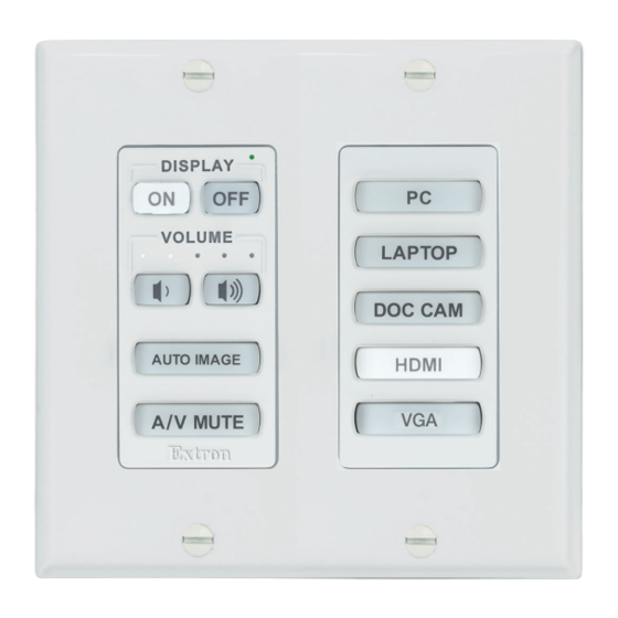
Transmit/ Source Control Reset Button Faceplate Tab Activity LED Buttons and LED Access Holes (4) Faceplates Display Power DISPLAY Buttons DISPLAY VOLUME Volume VOLUME LAPTOP LEDs LAPTOP Volume DOC CAM Buttons DOC CAM AUTO IMAGE HDMI AUTO IMAGE HDMI Function Buttons AV MUTE AV MUTE... -
Page 40: Transmit/Activity Led And Buzzer
Transmit/Activity LED and Buzzer NOTE: The behavior of the buzzer can be configured using Global Configurator to be globally disabled or to beep as desired. Transmit/Activity LED — This LED is located above the Display power buttons. This LED blinks green to indicate that a configuration or firmware is being uploaded. It also blinks in conjunction with buzzer beeps under other circumstances, as detailed below. - Page 41 Volume control options Global Configurator software lets you select whether the MLC Plus knob or buttons control the audio levels of the projector (or another AV device) or of an optional Extron amplifier. Once they are configured, the Volume buttons (D model) and Volume knob and Mute button (EU and MK models) can: •...
-
Page 42: Reset Features And Resetting The Unit
Control voltage range and mute The maximum output voltage range of pin C of the volume control port is 0 to +10 VDC. During configuration you can set the minimum and maximum output voltage to limit the minimum and maximum volume level for a specific Extron amplifier model and connected audio equipment. -
Page 43: Resetting The Unit
Resetting the Unit There are several reset modes that are available by pressing the Reset button. The Reset button is recessed, so use an Extron Tweeker, a pointed stylus, or a ballpoint pen to access it. See the reset modes table below for a summary of the modes. - Page 44 MLC Plus 84 Series Controller Reset Mode Summary Use This Activation Result Mode to... Recover For devices with a firmware version below 2.00.0001 project To start the Project Recovery reset mode and recover a project: Project Recovery mode stops regular configuration operation and allows a connection to be and program On the PC, open Global Configurator.
- Page 45 MLC Plus 84 Series Controller Reset Mode Summary Use This Activation Result Mode to... Toggle stop/ To stop or start a program: The LED blinks 2 times if the program is start program starting. Hold down the Reset button for about 3 seconds, until the Reset LED blinks once.
-
Page 46: Software-Based Configuration And Control
Software-Based Configuration and Control This section of the guide is divided into the following topics: • Configuration and Control: an Overview • Basic Setup Steps: a Guide to this Section and Other Resources • Downloading the Software and Getting Started •... -
Page 47: Basic Setup Steps: A Guide To This Section And Other Resources
Step 1: Get ready. Basic Setup Steps: a Guide to this Section and Other Resources Step 2: Prepare the installation site. NOTE: GC projects can be created offline and uploaded to the hardware at a later date. Step 3: Change buttons or faceplates, if desired Hardware Features and Installation Follow the steps in starting on page 6. -
Page 48: Locating Software, Firmware, And Driver Files On The Extron Website
Locating Software, Firmware, and Driver Files on the Extron Website There are three main ways to find software, firmware, and device drivers within www.extron.com: • Via links from the web page for the specific product Download Center • Via the page (click on the Download tab at the top of any page within the Extron website.) •... -
Page 49: Obtaining Control Drivers
To download a single driver rather than the package, click on the appropriate link in the row for the product you want to control to download the driver or to download the “communication sheet.” The communication sheet provides details that may be helpful for working with the product and its control driver. -
Page 50: Things To Do After Installing Gc And Before Starting A Project
Things to Do After Installing GC and Before Starting a Project • Read the Global Configurator Help File, included with the software, for details and step-by-step procedures on how to start a GC Professional or GC Plus project and perform basic setup tasks for a controller. The Global Configurator Help File provides a wealth of information on settings and how to use the software, itself. -
Page 51: Troubleshooting
Troubleshooting Turn on the input devices (DVD players, Blu-ray players, PCs, and other sources), output devices (display screens, projectors), the controller, and the PC. Push a front panel button or rotate the Volume knob. If an input or output AV device cannot be remotely controlled (does not respond as expected), check the following: Power Connections •... -
Page 52: Reference Information
Reference Information This section of the guide includes the following reference items: Network Requirements • • File Types: a Key to Extron-specific File Names • Secure Sockets Layer (SSL) Certificates To read product specifications, visit the MLC Plus 84 product pages at www.extron.com. Network Port Requirements Network administrators may find it useful to know which ports, protocols, and services are used by the MLC Plus 84 controllers, Global Configurator Plus and Professional software,... -
Page 53: Secure Sockets Layer (Ssl) Certificates
Secure Sockets Layer (SSL) Certificates Extron IP Link Pro controllers ship with factory-installed SSL certificates created by Extron. If you want or are required to use a different SSL certificate at your installation site, then you can use system utilities in the Toolbelt software to change the SSL certificate at any time. -
Page 54: Maintenance
Maintenance This section of the guide includes the following topics you may need in order to update, repair, or maintain the unit after installation: • Removing the MLC Plus EU or MK From the Mounting Surface • Firmware Updates Removing the MLC Plus EU or MK from the Mounting Surface Before you can replace buttons or faceplates on an MLC Plus 84 EU or MK, if the unit is installed in a wall or furniture, you must remove the unit from the metal mounting bracket and installation surface. -
Page 55: Firmware Updates
Firmware Updates If the need arises, you can replace the MLC Plus firmware. This section covers the following firmware-related topics: • Determining the Firmware Version • Updating the Firmware Determining the Firmware Version There are several ways to check which firmware version the controller is using: •... -
Page 56: Updating The Firmware
Updating the Firmware Firmware upgrade tools require the PC and the controller to both be connected to an Ethernet network. The instructions for updating the MLC Plus firmware assume you have installed the appropriate software on your PC first. NOTES: • You should save the existing configuration to a file (see the Global Configurator Help File for instructions) before replacing the firmware. - Page 57 Index IR emitters wiring for use with IR output ports 22 Americans with Disabilities Act (ADA) eir file type 44 compliance 9 Ethernet drivers IR output ports application diagram support for 3 use and wiring 22 system connections 4 LAN (IP) ports file type names and descriptions COM (serial) ports .eff 44...
- Page 58 relay ports troubleshooting 43 latching: description and data connections 43 wiring 25 device control connections and momentary contact: description configuration 43 and wiring 25 power connections 43 wiring 25 removal tool 46 Reset button Reset button and LED location 34 updating the firmware 48 using to reset the unit 35 username...
- Page 59 Extron Electronics makes no further warranties either expressed or implied with respect to the product and its quality, performance, merchantability, or fitness for any particular use. In no event will Extron Electronics be liable for direct, indirect, or consequential damages resulting from any defect in this product even if Extron Electronics has been advised of such damage.
Need help?
Do you have a question about the MediaLink MLC Plus 84 Series and is the answer not in the manual?
Questions and answers