Extron electronics MLC 104 IP Plus Series User Manual
Hide thumbs
Also See for MLC 104 IP Plus Series:
- Specification sheet (4 pages) ,
- Setup manual (7 pages)

Subscribe to Our Youtube Channel
Related Manuals for Extron electronics MLC 104 IP Plus Series


Summary of Contents for Extron electronics MLC 104 IP Plus Series
- Page 1 User Guide MediaLink Controllers ® MLC 104 IP Plus Series MediaLink Controllers with Ethernet Control 68-1443-01 Rev. C 11 18...
- Page 2 Safety Instructions Safety Instructions • English Istruzioni di sicurezza • Italiano AVVERTENZA: Il simbolo, , se usato sul prodotto, serve ad This symbol, ,when used on the product, is intended WARNING avvertire l’utente della presenza di tensione non isolata pericolosa to alert the user of the presence of uninsulated dangerous voltage within all’interno del contenitore del prodotto che può...
- Page 3 より 『Extron Safety www.extron.com and Regulatory Compliance Guide』 (P/N 68-290-01) をご覧ください。 Copyright www.extron.com © 2009-2018 Extron Electronics. All rights reserved. Trademarks All trademarks mentioned in this guide are the properties of their respective owners. The following registered trademarks ( ®...
- Page 4 FCC Class A Notice This equipment has been tested and found to comply with the limits for a Class A digital device, pursuant to part 15 of the FCC rules. The Class A limits provide reasonable protection against harmful interference when the equipment is operated in a commercial environment.
- Page 5 Conventions Used in this Guide Notifications The following notifications are used in this guide: WARNING: Potential risk of severe injury or death. AVERTISSEMENT : Risque potentiel de blessure grave ou de mort. CAUTION: Risk of minor personal injury. ATTENTION : Risque de blessure mineure. ATTENTION: Risk of property damage.
-
Page 7: Table Of Contents
............34 Before You Begin ..........1 Configuration and Control: an Overview .... 34 About the MLC 104 IP Plus Series Controllers ..1 Features ............2 The Basic Setup Steps: a Guide to This Section and Other Resources ......35 Controlling Other Devices ....... - Page 8 Controller ........... 127 Configuration ..........159 Using an Amplifier and Volume Controller with the MLC ..........132 Index ............160 Volume Control Hardware Setup ....133 Volume Control Software Setup ....134 MLC 104 IP Plus Series • Contents viii...
-
Page 9: Introduction
Throughout this guide the various models in the MLC 104 IP Plus Series are also referred to as the “MLC 104 IP Plus,” “MLC 104,” “MLC,” or “controller.” Global Configurator software is also referred to as “GC,”... -
Page 10: Features
E-mail notification — The MLC 104 IP Plus can be set up to send e-mail notifications, such as a notice that a projector has been disconnected or the projector lamp has been used for a designated number of hours. MLC 104 IP Plus Series • Introduction... -
Page 11: Controlling Other Devices
Laptop Full-range Ceiling Speakers Figure 1. Typical MLC 104 IP Plus Series Application IR and RS-232 Device Control The MLC must be configured in one of the following ways before it sends commands to a projector, display, or source device: •... -
Page 12: How The Mlc 104 Ip Plus Series Controllers Work: Components And Interactions
The event files define, monitor, and govern how a MLC 104 IP Plus Series controller works. The following diagram is an example of how the MLC interacts with accessories, event scripts, drivers, ports, input devices, and output devices. -
Page 13: Optional Control Modules
MLC (via IR Emitters) when the corresponding button is pressed on the front panel of the controller, SCP, or control module. See the Control Modules User’s Manual. CM-9BLB CM-20BB CM-9BLB Figure 3. Optional IRCM and CM Control Modules MLC 104 IP Plus Series • Introduction... -
Page 14: System Requirements
System Requirements The MLC 104 IP Plus Series and Global Configurator have the following minimum hardware and software requirements: Hardware Requirements Global Configurator Processor Intel Pentium III, 1 GHz ® ® 512 MB Available hard disk space 50 MB A network connection with a minimum data transfer rate of 10 Mbps (100 Mbps is... -
Page 15: Operation, Features, And Cabling
Unit— Information about the available reset modes and how to reset the MLC • Pinout Guides — An example application diagram that can be used as a cabling and pin assignment reference MLC 104 IP Plus Series • Operation, Features, and Cabling... -
Page 16: Setup Checklist
(DSS, cable boxes, and the like). … Test the system. … Mount the unit to an electrical box, wall, furniture, or rack and ground the unit (see Mounting Instructions on page 148). MLC 104 IP Plus Series • Operation, Features, and Cabling... -
Page 17: Ul And Safety Requirements
It is not included with the MLC. MLC 104 IP Plus series is only for use with UL Listed products. Unused AAP openings are to be covered with a blank AAP panel(s). -
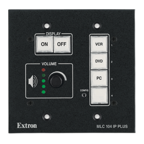
Page 18: Front Panel Features And Operation
NOTE: To avoid conflicts with the front panel lockout PIN feature, Extron recommends configuring the Display Power buttons so that the MLC sends projector or display commands upon the button release instead of on the button press. MLC 104 IP Plus Series • Operation, Features, and Cabling... -
Page 19: Volume Control
If the knob controls the audio levels of the projector, you can specify incremental adjustments or range-based adjustments (via device driver only). See the Global Configurator Help file for details. MLC 104 IP Plus Series • Operation, Features, and Cabling... -
Page 20: Configuration Port
PC connected to these ports is set for 38400 baud. • Extron recommends configuring and controlling the MLC via the LAN connector. Ethernet connections are faster and more reliable. MLC 104 IP Plus Series • Operation, Features, and Cabling... -
Page 21: Front Panel Security Lockout (Executive Mode)
System Settings factory default web page, front panel lockout cannot be enabled or disabled via the front panel unless PIN Mode is enabled. for the SIS command ( X? *60#) for PIN enabling and disabling. See page MLC 104 IP Plus Series • Operation, Features, and Cabling... - Page 22 This example shows the default administrator PIN: 1 2a , 4 2b , 2 2c , 3 2d . CONFIG Figure 5. Enabling and Disabling Front Panel Lockout Via the Front Panel MLC 104 IP Plus Series • Operation, Features, and Cabling...
-
Page 23: Preparing The Mlc For Front Panel Lockout
The diagram 2–12" indicates the best distances and angles at (4–30 cm) which to hold the remote control. Figure 6. MLC 104 IP Plus Top Panel MLC 104 IP Plus Series • Operation, Features, and Cabling... -
Page 24: Panel Features And Cabling
If using DataViewer, HyperTerminal, or a similar application, make sure the PC or control system connected to these ports is set for 38400 baud. MLC 104 IP Plus Series • Operation, Features, and Cabling... -
Page 25: Right And Rear Panel Features And Cabling
IR Emitter ground Side RS-232/IR COMM LINK COMM LINK Panel wires to a single wire that is inserted into this port. Figure 7. Wiring for RS-232 Display Control and IR Source Control MLC 104 IP Plus Series • Operation, Features, and Cabling... - Page 26 IR Emitters to those wires. To wire emitters, see the following figures and the IR Emitter Installation Guide. Wiring directions depend on the number and type of IR Emitters (single or dual). MLC 104 IP Plus Series • Operation, Features, and Cabling...
- Page 27 0.5 amperes. NOTE: SCP control panel or control modules (CM, IRCM) used with the MLC are affected by front panel security lockout (executive mode) status changes. MLC 104 IP Plus Series • Operation, Features, and Cabling...
- Page 28 3-pole connector of an SCP 104 instead of to its 5-pole connector, the buttons of CM-xBLB control module do not light. CM-3BLB CM-3BLB CM-3BLB Front CM-3BLB Rear CM-3BLB Rear CM-3BLB Front MLC 104 IP Plus Series • Operation, Features, and Cabling...
- Page 29 MLC. For example, if an IRCM-DV+ and a CM-5BB are connected to the port on the MLC, each SCP should have an IRCM-DV+ and a CM-5BB (and not other models) connected to its 3-pole connector. MLC 104 IP Plus Series • Operation, Features, and Cabling...
- Page 30 Configurator ou les commandes SIS, puis raccordez le câblage au port du MLC. Un défaut de concordance entre la configuration du port et le câblage peut entraîner le dysfonctionnement ou la défaillance de l’unité. MLC 104 IP Plus Series • Operation, Features, and Cabling...
- Page 31 MLC 104 IP Plus Use the port to monitor or trigger events and functions (toggle relays, issue Right Side Panel commands, send email), once con gured. Figure 14. Wiring for Digital Input MLC 104 IP Plus Series • Operation, Features, and Cabling...
- Page 32 +12 V +5.0 V Pin 1of the 2k ohms Host Control port or the Pwr Sns pin of the Projector port SW 2 Digital Status Input SW 1 Ground (GND) pin MLC 104 IP Plus Series • Operation, Features, and Cabling...
- Page 33 I/O pin is set to Output “on” (switch 1 is closed). SW 1 NOTE: The digital I/O pin is capable of sinking a maximum of 250 mA from 12 VDC, max. MLC 104 IP Plus Series • Operation, Features, and Cabling...
- Page 34 • 9600 baud • no parity MLS 506 PVS 305SA IP • 8 data bits • no flow control MLS 506MA 70 V MLA VC10 Plus • 1 stop bit MLS 506SA MLC 104 IP Plus Series • Operation, Features, and Cabling...
- Page 35 Receive (Rx) Heat Shrink Over Shield MLC 104 IP Plus right side panel MLS and Connecting an MLC 104 IP Plus Power ports to a PoleVault Switcher MLS PWR RS-232 12V MLC 104 IP Plus Series • Operation, Features, and Cabling...
- Page 36 725, et du Code canadien de l’électricité, partie 1, section 16. La source d’alimentation ne devra pas être fixée de façon permanente à la structure de bâtiment ou à d’autres structures similaires. MLC 104 IP Plus Series • Operation, Features, and Cabling...
- Page 37 Insert Twisted blue blue blue blue Pair Wires white-blue white-blue white-blue white-blue green green green orange TCP/IP white-brown white-brown white-brown white-brown Network brown brown brown brown T568B T568B T568B T568A MLC 104 IP Plus Series • Operation, Features, and Cabling...
-
Page 38: Top Panel: Ir Learning Sensor
The green LED flashes depending on the selected reset mode (see Resetting the Unit, page 31 for details). Reset Button (recessed) Left Side MLC 104 IP Plus Series • Operation, Features, and Cabling... -
Page 39: Resetting The Unit
Sets the default gateway address to the factory default • (0.0.0.0) Sets port mapping back to factory default • Turns DHCP off • Turns events off • The Reset LED flashes four times in quick succession during reset. MLC 104 IP Plus Series • Operation, Features, and Cabling... -
Page 40: Pinout Guides
From an external 12 VDC, 0.5 A (max.) power supply +12 VDC input +12V IN or an Extron switcher MLC 104 IP Plus Right Side Panel Figure 15. Right Side Panel Port and Pin Configuration Summary MLC 104 IP Plus Series • Operation, Features, and Cabling... - Page 41 LAN 2 5A MAX Receive (Rx) Transmit (Tx) Ground Ground PVS or +12 VDC in +12V MLS Switcher RS-232/MLC/IR port Heat Shrink Over Shield Figure 16. Example of Bottom Panel Connections MLC 104 IP Plus Series • Operation, Features, and Cabling...
-
Page 42: Software-Based Configuration And Control
• Alternatively the default web pages embedded within the MLC provide a means to perform some setup, adjustment, and control via a web browser from any type of network-enabled computer. MLC 104 IP Plus Series • Software-based Configuration and Control... -
Page 43: The Basic Setup Steps: A Guide To This Section And Other Resources
See Configuring the MLC for Network Communication on the next page to set the unit up to talk with the PC. MLC 104 IP Plus Series • Software-based Configuration and Control... -
Page 44: Configuring The Mlc For Network Communication
Configuring the MLC for Network Use Via Global Configurator You can configure the IP address of the controller via an IP (Ethernet) connection using the Extron Global Configurator (GC) software. See the Global Configurator Help file for basic MLC 104 IP Plus Series • Software-based Configuration and Control... -
Page 45: Configuring The Mlc For Network Use Via The Arp Command
NOTE: The MAC address is listed on the top panel. After the arp -s command is issued, the controller changes to the new address and starts responding to the ping requests, as described in the next step. MLC 104 IP Plus Series • Software-based Configuration and Control... - Page 46 After verifying that the IP address change was successful, enter and issue the arp –d command at the prompt. For example: arp –d 192.168.10.10 removes 192.168.10.10 from the ARP table. arp –d* removes all static IP addresses from the ARP table. MLC 104 IP Plus Series • Software-based Configuration and Control...
-
Page 47: Configuring The Mlc For Network Use Via A Web Browser
Once the IP address is changed, you lose communication with the controller. Close the browser. After changing the controller’s IP settings, change the TCP/IP settings of your PC back to their original configuration. MLC 104 IP Plus Series • Software-based Configuration and Control... -
Page 48: Configuring The Mlc For Network Use Via
IP address for the controller or confirm whether you need to set up the MLC for DHCP (Dynamic Host Configuration Protocol) to have an address assigned automatically when you sign on. MLC 104 IP Plus Series • Software-based Configuration and Control... - Page 49 For Windows XP, right-click on Local Area Connection, then select • Properties. For Windows 7, click on • Local Area Connection to open the Local Area Connection Status dialog box, then click Properties. MLC 104 IP Plus Series • Software-based Configuration and Control...
- Page 50 Write down the PC’s current IP address and subnet mask below. If your PC is set to “Obtain an IP address automatically,” make a note of that, instead. You will need to restore these settings to the PC later. IP address: Subnet mask: MLC 104 IP Plus Series • Software-based Configuration and Control...
- Page 51 Restore the previous IP configuration for the PC by following steps 1, 2, 3, and 5 but use the original IP address settings for the PC that you wrote down in step 4. MLC 104 IP Plus Series • Software-based Configuration and Control...
-
Page 52: Global Configurator Software For Windows
PC System Requirements See page in the “Introduction” section for a list of the minimum hardware and software requirements. NOTE: The MLC 104 IP Plus Series requires GC version 2.2 or higher. MLC 104 IP Plus Series • Software-based Configuration and Control... -
Page 53: Using Global Configurator: Helpful Tips
Valid characters are A to Z, a to z, 0 to 9, and - (hyphen). • The name cannot start with a number or a hyphen, and it cannot end with a • hyphen. Maximum name length is 24 characters. • MLC 104 IP Plus Series • Software-based Configuration and Control... -
Page 54: Advanced Configuration
MLC The Global Configurator Help file explains these features in the reference section about the Advanced Configuration tab and in the MLC-specific instructions for configuring MLC 104 IP Plus Series • Software-based Configuration and Control... - Page 55 47#, on page 106). If the maximum volume (47# command) is set, the limit audio level feature (SIS special command 11#, on page 100) is automatically set to 25% of the maximum volume (47#). MLC 104 IP Plus Series • Software-based Configuration and Control...
-
Page 56: Configuring An Auxiliary (Mls, Pvs) Switcher
RS-232 port, just like the Display port. To enable and configure an auxiliary switcher, follow the procedure in the Global Configurator Help file to add and configure a MediaLink or PoleVault switcher. MLC 104 IP Plus Series • Software-based Configuration and Control... -
Page 57: Setting Up Passwords
Word. Print the diagram and, if desired, save the file. Exit Word. Close the Global Configurator Print Wiring Diagrams/GUI Configuration Report window. MLC 104 IP Plus Series • Software-based Configuration and Control... -
Page 58: Updating Firmware
(baud rate, parity, stop bits) for the desired serial port on the MLC. Launch the DataViewer program. Click File > Connect to open the Communication Setup dialog box. Click the TCP/IP tab. MLC 104 IP Plus Series • Software-based Configuration and Control... - Page 59 This is not an advanced configuration function, but when you finish creating the configuration in Global Configurator, you must save the GC project and upload the configuration to one or more MLCs. See the Global Configurator Help file for instructions. MLC 104 IP Plus Series • Software-based Configuration and Control...
-
Page 60: Controlling An Mlc 104 Ip Plus
NOTE: Administrators have access to all of the web pages and are able to make changes to settings. Users can access the System Status and Control: User Mode pages only. MLC 104 IP Plus Series • Software-based Configuration and Control... - Page 61 NOTE: Projector lamp hours reflect time elapsed since the lamp was changed as determined by the driver or events associated with the Display RS-232/IR port on the MLC. Lamp hours can also be viewed using SIS command (see page 79). MLC 104 IP Plus Series • Software-based Configuration and Control...
- Page 62 0 by clicking the Reset Statistics button at the bottom of this screen. NOTE: This page is not available unless the MLC has been configured with Global Configurator version 2.x or higher. Figure 19. A Statistics Embedded Web Page MLC 104 IP Plus Series • Software-based Configuration and Control...
- Page 63 Valid characters are Ato Z, a to z, 0 to 9, and - (hyphen). • The name cannot start with a number or hyphen. It cannot end with a hyphen. MLC 104 IP Plus Series • Software-based Configuration and Control...
- Page 64 NOTE: The MLC must first be configured with Global Configurator before e-mail addresses and e-mail file names appear on this page. Figure 22. Email Alerts Embedded Web Page MLC 104 IP Plus Series • Software-based Configuration and Control...
- Page 65 Figure 23. Firmware Upgrade Embedded Web Page Firmware Updates NOTE: See the section (page 152) for instructions on how to update the firmware. MLC 104 IP Plus Series • Software-based Configuration and Control...
- Page 66 You can also view files in subfolders, including those containing GlobalViewer files or IP Intercom files if they have been installed on the MLC. The following screen view shows an example of the file management page for subfolders. MLC 104 IP Plus Series • Software-based Configuration and Control...
- Page 67 There are up to seven Control web pages, depending on the configuration of the MLC: User Mode • • IR Drivers • Up to five Serial Devices pages (Display Port, Port A, Port B, Port C, MLS Port) MLC 104 IP Plus Series • Software-based Configuration and Control...
- Page 68 Upload Enhanced Web Pages from the Advanced Configuration page in Global Configurator before you build the configuration and load it into the MLC. Figure 27. Enhanced User Mode Embedded Web Page MLC 104 IP Plus Series • Software-based Configuration and Control...
- Page 69 NOTE: You must use Microsoft Internet Explorer version 6.0 or higher with Active X enabled in order to use the control pages for the serial devices. MLC 104 IP Plus Series • Software-based Configuration and Control...
- Page 70 Example Page For an Extron MLS Switcher Connected to the MLS Port When “Disable MLS support (Enable serial driver support)” is Selected in GC Figure 31. Example Page For a Projector Driver Associated With the Display Port on the MLC MLC 104 IP Plus Series • Software-based Configuration and Control...
-
Page 71: Globalviewer Web Pages
See the Global Configurator Help file for details about each screen and how to use the GlobalViewer pages. The following figures are examples of MLC GlobalViewer pages. MLC 104 IP Plus Series • Software-based Configuration and Control... - Page 72 (the projector or display and input devices). You can click the GlobalViewer on-screen buttons to send the corresponding command from the MLC to that device. MLC 104 IP Plus Series • Software-based Configuration and Control...
- Page 73 (projector disconnection, lamp hours, and the like) are being monitored, under what conditions, and who receives an e-mail notification about each condition. This information appears only if the MLC has been configured to monitor such conditions. MLC 104 IP Plus Series • Software-based Configuration and Control...
- Page 74 MLC front panel controls are locked and unlocked. You can also see what actions are associated with each schedule and to enable or disable each action. MLC 104 IP Plus Series • Software-based Configuration and Control...
-
Page 75: Customizing The Mlc Control Web Pages
• • A company or institution logo Visit the Extron website (http://www.extron.com/product/customgui.aspx) or contact an Extron customer support representative for more information on this service and on available template options. MLC 104 IP Plus Series • Software-based Configuration and Control... -
Page 76: Troubleshooting
MLC and on the other devices. Extron S3 Sales & Technical Support If you are still experiencing problems, call the Hotline or the Extron S3 Control Systems Support Hotline. MLC 104 IP Plus Series • Software-based Configuration and Control... -
Page 77: Sis Programming And Control
RS-232 only. The MLC 104 IP Plus Series controller can be remotely controlled via a host computer or other device (such as a control system) attached to the front panel Config port, or to the rear panel LAN port connected to a shared network. -
Page 78: Host-To-Mlc Communications
The unit sends this response when an input is switched. Vol X*] (where X* is the volume step number) The unit sends this response when the volume knob is rotated. (c) Copyright 2008, Extron Electronics, MLC 104 IP PLUS, Vx.xx, 60-818-00 ] Day, DD Mon YYYY HH:MM:SS ] Vx.xx is the firmware version number. -
Page 79: Error Responses
MLC to the host, and a description of the function of the command or the results of executing the command. Figure 36. ASCII to Hex Conversion Table MLC 104 IP Plus Series • SIS Programming and Control ™... -
Page 80: Entering Sis Commands: Helpful Tips
RS-232 or IP communication, it takes up to 1 minute 40 seconds (100 seconds) for the data in the RAM of the MLC to be saved to flash memory. Do not remove power during that period. MLC 104 IP Plus Series • SIS Programming and Control ™... -
Page 81: Symbol Definitions
No distinction is made between upper and lower case. The first character must be a letter. The last character must not be a minus sign or hyphen. MLC 104 IP Plus Series • SIS Programming and Control ™... - Page 82 = I/O mode 1 = use configure receive timeout 0 = input (default) command parameters 1 = output 2 = input and pull-up resistor 3 = output and pull-up resistor MLC 104 IP Plus Series • SIS Programming and Control ™...
- Page 83 10-second steps (1 - 65000, default = 30 = 2 = unknown/unavailable (default for connection 300 seconds). If no data is received during status) the specified period, the Ethernet connection closes. Responses are returned with leading zeros. MLC 104 IP Plus Series • SIS Programming and Control ™...
- Page 84 NOTE: For commands and examples of computer or device responses mentioned in this guide, the character “0” is used for the number zero and “O” represents the capital letter “o”. MLC 104 IP Plus Series • SIS Programming and Control...
-
Page 85: Command/Response Table For Sis Commands
Command/Response Table for SIS Commands Command ASCII (Telnet) URL Encoded (web) Response Additional Description (host to MLC) (host to MLC) (MLC to host) Input selection Select an input X20) X20) X20) ] X20) X20) 14, 22 Select input = 1, 2, 3, 4) (audio and video). - Page 86 Command/Response Table for SIS Commands (continued) Command ASCII (Telnet) URL Encoded (web) Response Additional Description (host to MLC) (host to MLC) (MLC to host) Volume adjustment (discrete, for volume mode = 0) Set the overall output volume This command sets a specific volume level for level the audio output either at the display device or via an optional slaved Extron MediaLink (MLS)
- Page 87 Command/Response Table for SIS Commands (continued) Command ASCII (Telnet) URL Encoded (web) Response Additional Description (host to MLC) (host to MLC) (MLC to host) View lockout mode status X20(] Show lockout (executive mode) status. X20( = 0 (off, unlocked) or 3 (front panels, control modules, and remote control locked/ disabled).
- Page 88 Command/Response Table for SIS Commands (continued) Command ASCII (Telnet) URL Encoded (web) Response Additional Description (host to MLC) (host to MLC) (MLC to host) Serial port configuration and use These commands apply to any port that uses RS-232 communication: both 1-way (output) and 2-way (bidirectional) RS-232 communication. Send data string E X! X1&...
- Page 89 Command/Response Table for SIS Commands (continued) Command ASCII (Telnet) URL Encoded (web) Response Additional Description (host to MLC) (host to MLC) (MLC to host) Configure serial port parameters E X! X2& Set baud rate ( ), parity ( ), data bits X2&...
- Page 90 Command/Response Table for SIS Commands (continued) Command ASCII (Telnet) URL Encoded (web) Response Additional Description (host to MLC) (host to MLC) (MLC to host) Set global Ethernet connection X6( ] The global port timeout is the default timeout W 1 %2A Pti 1* timeout period period for all Telnet sessions.
- Page 91 Command/Response Table for SIS Commands (continued) Command ASCII (Telnet) URL Encoded (web) Response Additional Description (host to MLC) (host to MLC) (MLC to host) Digital I/O data port (dedicated Digital I/O ports) configuration and use An input voltage below 2.0 VDC is considered to be logic low. An input voltage above 2.8 VDC is considered to be logic high. These thresholds are not adjustable. NOTE: Set the input/output (I/O) mode X22#...
- Page 92 Command/Response Table for SIS Commands (continued) Command ASCII (Telnet) URL Encoded (web) Response Additional Description (host to MLC) (host to MLC) (MLC to host) Firmware version, part number, and information requests E X2@ Responses to commands differ depending on which, if any, verbose response mode the MLC is in. See the CV command , page 88) under IP NOTE:...
- Page 93 Command/Response Table for SIS Commands (continued) Command ASCII (Telnet) URL Encoded (web) Response Additional Description (host to MLC) (host to MLC) (MLC to host) Query updated firmware version (kernel version–model description–date time of upload) or Ver04* (kernel version–model description–date time of upload) Use this command to find out which version of the firmware, if any, was uploaded into the...
- Page 94 Command/Response Table for SIS Commands (continued) Command ASCII (Telnet) URL Encoded (web) Response Additional Description (host to MLC) (host to MLC) (MLC to host) Request status of attached hardware P1##•P2##•K1##•K2##•K3##•K4##•S** P1##•P2##•K1##•K2##•K3##•K4##•S**•IPI??? Show the absence of or types of connected devices. Prefixes for connected devices: For ##: P1 = SCP #1, address 0...
- Page 95 Command/Response Table for SIS Commands (continued) Command ASCII (Telnet) URL Encoded (web) Response Additional Description (host to MLC) (host to MLC) (MLC to host) Set date/time E X1# X1#] Ipt• = Local date and time format. The set format is MM/DD/YY-HH:MM:SS. Example: 01/31/11-10:54:00.
- Page 96 Command/Response Table for SIS Commands (continued) Command ASCII (Telnet) URL Encoded (web) Response Additional Description (host to MLC) (host to MLC) (MLC to host) Get a connection listing Display the number of currently active IP {number of connections} client connections. Icc {number of connections} Example: Example: This shows two client connections.
- Page 97 Command/Response Table for SIS Commands (continued) Command ASCII (Telnet) URL Encoded (web) Response Additional Description (host to MLC) (host to MLC) (MLC to host) Password and security settings Read the security level of the X5@ ] connection X5@ ] or Pvl 0 = not logged in 11 = user 12 = administrator.
- Page 98 Command/Response Table for SIS Commands (continued) Command ASCII (Telnet) URL Encoded (web) Response Additional Description (host to MLC) (host to MLC) (MLC to host) Remapping port designations For security reasons the network administrator may wish to assign new/different port numbers to the Telnet, web browser, and direct access ports of the controller or to disable one or more ports.
- Page 99 Command/Response Table for SIS Commands (continued) Command ASCII (Telnet) URL Encoded (web) Response Additional Description (host to MLC) (host to MLC) (MLC to host) Directory commands Change or create a directory The directory name must be composed of path/directory/ CJ alphanumeric characters and may include the W path %2F directory %2F CJ minus sign (hyphen, -) and the colon (:).
- Page 100 Command/Response Table for SIS Commands (continued) Command ASCII (Telnet) URL Encoded (web) Response Additional Description (host to MLC) (host to MLC) (MLC to host) List files from the current directory W DF [filename 1]•[day, date time of upload]GMT•[file size 1 in bytes] [filename 2]•[day, date time of upload]GMT•[file size 2 in bytes] [filename 3]•[day, date time of upload]GMT•[file size 3 in bytes] …...
- Page 101 Command/Response Table for SIS Commands (continued) Command ASCII (Telnet) URL Encoded (web) Response Additional Description (host to MLC) (host to MLC) (MLC to host) File streaming commands File streaming commands should be used by advanced programmers only. NOTE: Load a file to user flash memory via Telnet or RS-232 24, 28 + UF filesize, filename {raw, unprocessed data in a file of up to filesize}...
- Page 102 Command/Response Table for SIS Commands (continued) Command ASCII (Telnet) URL Encoded (web) Response Additional Description (host to MLC) (host to MLC) (MLC to host) E-mail commands E X4% X4& Configure e-mail events (mailbox) = e-mail event number (1 - 64). X4&...
- Page 103 Command/Response Table for SIS Commands (continued) Command ASCII (Telnet) URL Encoded (web) Response Additional Description (host to MLC) (host to MLC) (MLC to host) Set e-mail server IP address and user domain name = IP address (xxx.xxx.xxx.xxx). E X1$ Leading zeros are optional in setting values; they are suppressed in returned values.
- Page 104 Command/Response Table for SIS Commands (continued) Command ASCII (Telnet) URL Encoded (web) Response Additional Description (host to MLC) (host to MLC) (MLC to host) Event control Start events 24,27 Start all events. W 1AE Stop events Stop running all events. 24,27 W 0AE Query quantity of events running...
- Page 105 Command/Response Table for SIS Commands (continued) Command ASCII (Telnet) URL Encoded (web) Response Additional Description (host to MLC) (host to MLC) (MLC to host) Select firmware or script control of buttons This command determines whether the firmware or a script (software-generated E X21! X21! X21!]...
- Page 106 Command/Response Table for SIS Commands (continued) Command ASCII (Telnet) URL Encoded (web) Response Additional Description (host to MLC) (host to MLC) (MLC to host) Button LED control E X21@ X21@ X21@] This command specifies which front panel buttons (Power On, Power Off, and/or input (set button color/lighting) selection buttons) light and in what colors.
- Page 107 Command/Response Table for SIS Commands (continued) Command ASCII (Telnet) URL Encoded (web) Response Additional Description (host to MLC) (host to MLC) (MLC to host) Set button LEDs to blink fast X21@ X21@ X21@] W 2%2A Lbk*2* Read which button LEDs are set X21@] W 2LX to blink fast...
-
Page 108: Command/Response Table For Special Function Sis Commands
(47# command) is set, the limit audio level feature (11# command) is automatically set to 25% of the maximum volume (47#). Example: Example: limit power-up volume to 28*11# VolLimit*028 28% of maximum volume. MLC 104 IP Plus Series • SIS Programming and Control ™... - Page 109 3&4) of the IRCM-DV+ with MLC buttons, you cannot activate and use either the DVD or the VCR part of the IRCM-DV+. For MLC 104 IP Plus Series MediaLink Controllers, you can assign both the DVD and VCR portions of an NOTE: IRCM-DV+ to the same input selection button.
- Page 110 The input button register numbering shown in the following illustrations is for a stand-alone MLC. It does not include button numbering for an optional switcher connected to the MLS port. Button/Switch Memory Block Numbering for the MLC 104 IP Plus Series, SCP 104 Series, and IR 402 MLC 104 Plus Series SCP 104...
- Page 111 • Module 2: memory blocks 46-65. has memory • Module 3: memory blocks 66-85. blocks • Module 4: memory blocks 86-105. • • • • • • 86-105. • • • CM-9BLB CM-9BLB — MLC 104 IP Plus Series • SIS Programming and Control ™...
- Page 112 Example: emulate pressing and 9*44# SwCmd*9 releasing the first input button. Actions associated with the button press are executed first, followed directly by actions associated with the button release. MLC 104 IP Plus Series • SIS Programming and Control ™...
- Page 113 See the variables for the command shown above. Clear (turn off) the button repeat This command clears the button 0*0*45# RptRate*000*00000 repeat setting and turns off the button repeat function. MLC 104 IP Plus Series • SIS Programming and Control ™...
- Page 114 The more the encoder speed decreases, the more turns or ..., button presses it takes to change the volume by the same amount. 255 = decrease encoder speed by 256. MLC 104 IP Plus Series • SIS Programming and Control ™...
- Page 115 Disable IR reception * 65# IRDisable* 0 = enable all IR ports (default), 2 = disable the rear panel IR port (input from IR devices and SCPs through the CM/IR/SCP port). MLC 104 IP Plus Series • SIS Programming and Control ™...
-
Page 116: Special Applications
If you press the input 4 button once, the MLC sends the video mute command. The next time you press that button, the MLC sends the video MLC 104 IP Plus Series • Special Applications... -
Page 117: Prerequisite Setup Steps
In Global Configurator, add device drivers and assign them to the Projector RS-232/IR port or MLS port (see the Global Configurator Help file for detailed procedures). NOTE: For monitoring, the device must be connected to one of the bidirectional ports on the MLC. MLC 104 IP Plus Series • Special Applications... -
Page 118: Setting Up The Front Panel Button
NOTE: Extron recommends that you always assign monitored functions to the button release for best results. For Toggle, click 1 to associate the AV Mute On command with the first button release. MLC 104 IP Plus Series • Special Applications... - Page 119 Click on the newly added button lighting command in the Release area. Click Toggle 2. TIP: Basic button setup is covered in the front panel tab section of the Global Configurator Help file, in case you want to review those steps during configuration. MLC 104 IP Plus Series • Special Applications...
-
Page 120: Setting Up Monitoring Conditions
Click on the name of the projector in the Device panel (NEC MT1050, in this example, as shown below). Click the Video Mute: On command in the Status Commands panel. Click the Apply Condition button. MLC 104 IP Plus Series • Special Applications... - Page 121 Click on the name of the projector in the Device panel. Click the Video Mute: Off command in the Action Commands panel. Click the Apply Condition button. Click Actions in the Monitored Conditions panel. MLC 104 IP Plus Series • Special Applications...
-
Page 122: Working With Combination Source Devices
Using separate source output ports on the DVD-VCR player • • Using a distribution amplifier with the switcher • Using separate IRCM control modules for DVD-VCR control • Using an IRCM-DV+ control module for DVD-VCR control MLC 104 IP Plus Series • Special Applications... -
Page 123: Using An Ircm-Dv+ Control Module And One Mlc Input Button For Dvd-Vcr Control
MLC to the project, if that has not already been done. For instructions, see the Global Configurator Help file. In Global Configurator, add device drivers and assign them to the Display RS-232/IR port. For instructions on these tasks, see the Global Configurator Help file. MLC 104 IP Plus Series • Special Applications... - Page 124 In the Driver tab within the Button Operations panel, double-click the name of the DVD-VCR player. A list of available driver functions is displayed below the driver name. MLC 104 IP Plus Series • Special Applications...
- Page 125 Set the actions for the VCR part of the player using the procedure outlined in step 9 but selecting VCR and toggle 2. Click the name of any other IR command that should be sent to the DVD/VCR player and assign it to the desired press or release. MLC 104 IP Plus Series • Special Applications...
- Page 126 In the Press area, select the user-defined command added in step 12i. For Toggle, click 2 to associate the DVD control of the IRCM-DV+ with the second button press. NOTE: This special function SIS command, X?*Y?*24#, is explained on page 101. MLC 104 IP Plus Series • Special Applications...
- Page 127 Select device drivers. • Configure the rest of the buttons (including IRCM-DV+ buttons). • Configure e-mail settings. • Set scheduling as appropriate. • Save the project. Build and upload the configuration to the MLC. MLC 104 IP Plus Series • Special Applications...
-
Page 128: Scheduling Front Panel Lockout Periods
3. Type in text for the on-screen button label and the tool tip (text that appears when the mouse pointer hovers over that button). Select the Single Switch button mode. MLC 104 IP Plus Series • Special Applications... - Page 129 Condition Name area. Click Emails in the Monitored Conditions area on the left. The right side of the window changes to show areas for e-mail messages and contacts (e-mail recipients). MLC 104 IP Plus Series • Special Applications...
-
Page 130: Working With A Non-Medialink Extron Switcher
Switcher (MLS) or PoleVault Switcher (PVS). The MLC recognizes and communicates with MLS and PVS switchers without requiring additional drivers or configuration, unless you want to remap switcher inputs to the buttons on the MLC. MLC 104 IP Plus Series • Special Applications... - Page 131 Select (double-click) Extron Generic switcher. If you want to use the buttons on the MLC to control MPS switcher inputs other than the default inputs 1 through 4, remap the front panel buttons. MLC 104 IP Plus Series • Special Applications...
-
Page 132: Using Digital Inputs
NOTE: This feature can be used as an alert notification and should not be used as a life safety feature, as it operates over a local network and offers no redundant means of communication if the network goes down. MLC 104 IP Plus Series • Special Applications... - Page 133 If the contact person for this alert is not listed in the Contacts panel, create a contact entry. Click Contact Manager. The Contacts Manager window opens. Type in the recipient name, e-mail address, and company information. MLC 104 IP Plus Series • Special Applications...
- Page 134 Save the configuration, then build and upload it to the MLC. Cable the digital input ports on the MLC to the appropriate pins of the button panel or switch, as shown in the following diagram. MLC 104 IP Plus Series • Special Applications...
-
Page 135: Using Digital Outputs
However, with the addition of an Extron IPA T RLY4 relay controller and a few configuration steps, you can still raise or lower a projection screen using the MLC, a screen controller, and a screen control motor. MLC 104 IP Plus Series • Special Applications... - Page 136 Low Voltage Controller Figure 38. Examples of Wiring an IPA T RLY4 to Low Voltage Screen Controllers Cable the screen controller to the drive motor for the screen according to that equipment’s installation instructions. MLC 104 IP Plus Series • Special Applications...
- Page 137 In the IP Link tree view panel, click on the MLC to be configured. Click on the Advanced Configuration tab. In the Digital Input/Output panel, use the drop-down menus to set each of the three ports to Output. MLC 104 IP Plus Series • Special Applications...
- Page 138 This command ensures that the relay is open (off) before it is pulsed. Click the green arrow ( ) adjacent to the Press area or drag the command to the Press area. MLC 104 IP Plus Series • Special Applications...
- Page 139 Output #2 and click Off. This command ensures that the relay is open (off) before it is pulsed. Click the green arrow ( ) adjacent to the Press area or drag the command to the Press area. MLC 104 IP Plus Series • Special Applications...
-
Page 140: Using An Amplifier And Volume Controller With The Mlc
MLC 104 IP Plus Module MediaLink Controller RS-232 MPA 152 Plus 12 VDC Mini Power Ampli er FI E P LI M IN ST ER Speakers 12 VDC, 0.5 A Power Supply MLC 104 IP Plus Series • Special Applications... -
Page 141: Volume Control Hardware Setup
The MLA VC10 Plus does not require configuration. The MLA-VC10 requires DIP switches to be set for the appropriate output voltage (see the MLA‑VC10 User Guide for details). The Extron MPA 122, MPA 181T, and MPA 152 accept up to 10 VDC. MLC 104 IP Plus Series • Special Applications... -
Page 142: Volume Control Software Setup
GlobalViewer area at the bottom of the window. Configure the MLC front panel volume control knob to control the MLA VC10 Plus (see image on next page). Click the Front Panel tab. Click the Volume Up button. MLC 104 IP Plus Series • Special Applications... - Page 143 Click the green arrow adjacent to the Press area or drag the command to the Press area. Complete the rest of the configuration as desired, then save the project and build and upload the configuration to the MLC. MLC 104 IP Plus Series • Special Applications...
-
Page 144: Customizing Html Files To Control Devices, Modify Embedded Web Pages, And Send E-Mail Alerts
SSIs being used, the slower the server processor) when planning your installation. NOTE: For the MLC and most other web servers, an SSI-enabled HTML file must have a file extension of .shtml. MLC 104 IP Plus Series • Special Applications... - Page 145 SSIs to insert the unit name, IP address, and time into an e-mail that is sent when the MLC detects that a device attached to it has been disconnected. For more MLC 104 IP Plus Series • Special Applications...
- Page 146 File streaming commands in the SIS section) via DataViewer, Telnet, or HyperTerminal • A web browser by sending a Post command on port 80 followed by the delimited data in the .shtml file MLC 104 IP Plus Series • Special Applications...
-
Page 147: Reference Material
The Global Configurator program performs this compilation and uploads the compiled event file onto the MLC. The Extron C language is similar to ANSI C, with some differences. As long as event scripts are turned on, they run continuously on the unit. MLC 104 IP Plus Series • Reference Material... - Page 148 Internet. It is an address mask used to identify the bits of an IP address that are used for the subnet address. Using a mask, the router does not need to examine all 32 bits, only those selected by the mask. MLC 104 IP Plus Series • Reference Material...
- Page 149 88 in the “SIS Programming and Control” section. Verbose mode is usually enabled for troubleshooting and disabled for daily use. Verbose mode creates more network traffic than usual and can slow down performance. MLC 104 IP Plus Series • Reference Material...
-
Page 150: File Types: A Key To Extron-Specific File Names
152 for details on firmware updates. Firmware cannot be updated by loading an .s19 file through the File Management page, but it can be updated via the Firmware Upgrade web page (see page 57). MLC 104 IP Plus Series • Reference Material... -
Page 151: Cut-Out Templates
(11.43 cm) (7.1 cm) FOR FURNITURE MOUNT Location of MLC 104 IP Plus To install the MLC 104 IP Plus TEMPLATE IS NOT FULL SIZE. directly into furniture, cut along this solid line. MLC 104 IP Plus Series • Reference Material... -
Page 152: Mlc 104 Ip Plus Aap And Mlc 104 Ip Plus Dv
8.23" (20.9 cm) To install the MLC 104 IP Plus AAP/DV+ directly into furniture, cut along this solid line. SURFACE CUT-OUT AREA Top Panel FOR FURNITURE MOUNT TEMPLATE IS NOT FULL SIZE. MLC 104 IP Plus Series • Reference Material... -
Page 153: Mlc 104 Ip Plus L
Location of MLC 104 IP Plus (16.5 cm) To install the MLC 104 IP Plus L directly into furniture, cut along this line. .250" (.64 cm) .295" (.75 cm) TEMPLATE IS NOT FULL SIZE. MLC 104 IP Plus Series • Reference Material... -
Page 154: Dimensions
6.50" (166 mm) 2.70" 2.70" (69 mm) (69 mm) 4.50" (115 mm) 3.15" (80 mm) 2.36" 2.36" (60 mm) (60 mm) MLC 104 IP Plus L MLC 104 IP Plus Rear Rear MLC 104 IP Plus Series • Reference Material... -
Page 155: Mlc 104 Ip Plus Dv+ And Mlc 104 Ip Plus Aap Dimensions
(46 mm) 8.23" 3.38" (209 mm) 4.50" (86 mm) (115 mm) MLC 104 IP Plus DV+ 2.70" Rear (69 mm) 2.36" (60 mm) 4.50" (115 mm) MLC 104 IP Plus AAP Rear MLC 104 IP Plus Series • Reference Material... -
Page 156: Mounting Instructions
For guidelines, see sections 307 (“Protruding Objects”) and 308 (“Reach Ranges”) of the 2010 ADA Standards for Accessible Design available at http://www.ada.gov/regs2010/2010ADAStandards/2010ADAStandards.pdf. MLC 104 IP Plus Series • Reference Material... -
Page 157: Mounting The Mlc To An Electrical Box Or Mud Ring
A licensed, bonded craftsperson is recommended for that task. If you have an MLC 104 IP Plus Series model other than the MLC 104 IP Plus L, remove the four faceplate attachment screws and remove the original faceplate, if applicable. -
Page 158: Rack Mounting An Mlc 104 Ip Plus L
Reliable earthing (grounding) — Maintain reliable grounding of rack-mounted equipment. Pay particular attention to supply connections other than direct connections to the branch circuit (such as use of power strips). MLC 104 IP Plus Series • Reference Material... - Page 159 Extron UCM-RAAP Extron MLC 104 IP Plus L D IS P lu 4 IP Figure 42. Rack Mounting the MLC 104 IP Plus L MLC 104 IP Plus Series • Reference Material...
-
Page 160: Firmware Updates
(see the Software-based Configuration and Control section starting on page 34) or to the optional GlobalViewer web page stored in the MLC (see the Global Configurator Help file for details). MLC 104 IP Plus Series • Firmware Updates... - Page 161 System Description panel, as shown at right. Select the System Settings page within the Configuration tab. The • firmware version is listed in the IP Settings panel, as shown below. MLC 104 IP Plus Series • Firmware Updates...
-
Page 162: Updating The Main Firmware
MLC_104_IP_PLUS_19_1818_50_vx.xx.S19 where vx_xx indicates the version number. NOTE: The firmware update file must have a filename extension of .s19. If the file does not have that extension, it does not work properly. MLC 104 IP Plus Series • Firmware Updates... -
Page 163: Updating Firmware Via Extron Ip Link File Manager Software
See command details on page 99 in the SIS section. Click on the Tools menu and select Firmware Update Manager. The Firmware Update Manager window appears (see image at right). MLC 104 IP Plus Series • Firmware Updates... - Page 164 If uploading fails, you can view the error log by clicking on View Log. If uploading is successful, the Status column indicates success for each unit. Click Close. Close the IP Link File Manager software. MLC 104 IP Plus Series • Firmware Updates...
-
Page 165: Updating Firmware Via The Mlc 104 Ip Plus Embedded Web Page
A screen like the one shown on the following page appears. Click the Browse button. A Choose File to Upload dialog box opens. Figure 44. Selecting the New Firmware File for the Upgrade MLC 104 IP Plus Series • Firmware Updates... -
Page 166: Updating Firmware Via Extron Firmware Loader Software
With that MLC unit selected, click Begin. The PC uploads the new firmware to the MLC. Once the firmware is uploaded, the MLC restarts events. Firmware Loader displays the new firmware version in the Firmware column. MLC 104 IP Plus Series • Firmware Updates... -
Page 167: Resetting The Mlc And Restoring Its Configuration
The ZY reset is different from reset modes 1 through 4. For details about reset Reset (zap) commands and modes available using SIS commands, see erase commands on page 99. Using Global Configurator, restore (build) the previously saved project to the MLC. MLC 104 IP Plus Series • Firmware Updates... -
Page 168: Index
IP network setup 37 a slaved switcher) 105 sent by the MLC 70 ASCII to decimal conversion types, functions, and table 80 operation 10 ASCII to hex conversion table 71 virtual mapping for an IRCM-DV+ 101 MLC 104 IP Plus Series • Index... - Page 169 (.evt) files .eml file type 142 direct access port map attention/caution about file setting initial port number, SIS deletion 58 command for 90 display connection status SIS commands 79 display control 3 MLC 104 IP Plus Series • Index...
- Page 170 29, 69 DHCP off and automatic reset to default IP address 87 SIS commands to set and read 87 IPA T RLY4 using for screen control 127 IP Link File Manager software 155 MLC 104 IP Plus Series • Index...
- Page 171 MLA-VC10 volume controller troubleshooting 68 using with MLC and amplifier 131 using the ping command with the MLC-initiated messages 70 arp command in IP setup 38 MLS connector pinout guide 32 wiring and protocol 26 MLC 104 IP Plus Series • Index...
- Page 172 87 s19 file type increment/decrement based 12 system requirements 6 file type description 142 range-based 12 System Settings (GlobalViewer Schedule (GlobalViewer web web page) 55 page) 66 scheduling front panel lockout periods 120 MLC 104 IP Plus Series • Index...
- Page 173 SIS commands to reset the unit and/or erase files 99 changing to hexadecimal equivalent characters 72 requirement within command data section in SIS commands 73 server side includes and 136 wiring block diagram printing 49 MLC 104 IP Plus Series • Index...
- Page 174 Extron Electronics makes no further warranties either expressed or implied with respect to the product and its quality, performance, merchantability, or fitness for any particular use. In no event will Extron Electronics be liable for direct, indirect, or consequential damages resulting from any defect in this product even if Extron Electronics has been advised of such damage.
Need help?
Do you have a question about the MLC 104 IP Plus Series and is the answer not in the manual?
Questions and answers