
Related Manuals for Extron electronics MediaLink MLC Plus 50


Summary of Contents for Extron electronics MediaLink MLC Plus 50
- Page 1 User Guide MediaLink Products ® MLC Plus 50/100/200 Series MediaLink Plus Controllers MLC Plus 50 MLC Plus 100 MLC Plus 100 AAP MLC Plus 200 MLC Plus 200 AAP 68-2806-01 Rev. C 03 18...
- Page 2 Safety Instructions Safety Instructions • English Istruzioni di sicurezza • Italiano AVVERTENZA: Il simbolo, , se usato sul prodotto, serve ad WARNING: This symbol, ,when used on the product, is avvertire l’utente della presenza di tensione non isolata pericolosa intended to alert the user of the presence of uninsulated dangerous all’interno del contenitore del prodotto che può...
- Page 3 All trademarks mentioned in this guide are the properties of their respective owners. The following registered trademarks , registered service marks , and trademarks are the property of RGB Systems, Inc. or Extron Electronics (®) (SM) (™) (see the current list of trademarks on the Terms of Use page at www.extron.com):...
- Page 4 FCC Class A Notice This equipment has been tested and found to comply with the limits for a Class A digital device, pursuant to part 15 of the FCC rules. The Class A limits provide reasonable protection against harmful interference when the equipment is operated in a commercial environment.
- Page 5 Conventions Used in this Guide Notifications The following notifications are used in this guide: CAUTION: Risk of minor personal injury. ATTENTION : Risque de blessure mineure. ATTENTION: • Risk of property damage. • Risque de dommages matériels. NOTE: A note draws attention to important information. TIP: A tip provides a suggestion to make working with the application easier.
-
Page 7: Table Of Contents
Contents Introduction Operation ........... 1 ............. 28 Before You Begin ..........1 Front Panel Features ......... 28 What This Guide Covers ......... 1 Faceplates ............ 30 Conventions Used in This Guide ..... 1 Mounting Holes ..........30 Important Information You Need Before Buttons............ - Page 8 Glossary Index ............46 ............. 49 MLC Plus 50/100/200 Series • Contents...
-
Page 9: Introduction
Introduction This section covers the following information you should know about this guide and the products before installation: • Before You Begin — What this guide covers and does not cover, and what terms are used to refer to this product •... -
Page 10: About The Mlc Plus 50/100/200 Series
About the MLC Plus 50/100/200 Series The MLC Plus 50/100/200 Series Controllers integrate Ethernet connection into AV systems to allow users to remotely control, monitor, and troubleshoot AV equipment. This equipment includes, but is not limited to, display devices and switchers, source devices, and various other items such as lights, a projector lift, or a screen motor. They can be used in a distributed control system environment or as stand-alone controllers. - Page 11 • The MLC Plus 200 and MLC Plus 200 AAP models feature ten buttons and a knob. The MLC Plus 200 fits a standard US three-gang junction box or mud ring. • Figure 4. MLC Plus 200 Front (Left), Rear (Middle), and Side (Right) Views The MLC Plus 200 AAP fits a standard US five-gang junction box or mud ring and •...
-
Page 12: Features
Features General features • Flexible options for device control Controlling the MLC — All models offer front panel controls. The MLC can also • be controlled using Extron Control apps, or digital input signals. Controlling other devices — The MLC Plus 50/100/200 Series models offer •... -
Page 13: Application Diagrams
• Network connection — The MLC Plus 50/100/200 models support 10Base-T up to gigabit (1000Base-T) Ethernet communication. • Remote equipment management — The IP Link Pro connection via the LAN port on the MLC Plus allows you to remotely manage, monitor, and control several Ethernet-enabled products such as projectors, cameras, video conferencing equipment, switchers, and other AV equipment. - Page 14 Extron 100-240V 0.5A MAX, 50-60Hz XPA 1002 Plus ATTENUATION INPUTS REMOTE 8 / 4 OUTPUTS XPA 1002 Plus 50mA LIMITER/PROTECT Laptop Power Ampli er SIGNAL ∞ ∞ CLASS 2 WIRING Microphones HDMI Extron Extron Audio Extron SM 26 WiFi 1 2 3 4 Speakers Audio Audio...
-
Page 15: Device Control
Extron FF 220T WiFi 1 2 3 4 Ceiling Speakers Extron DTP HDMI 330 Rx Receiver Screen Control LINK OUTPUTS POWER AUDIO 0.7A MAX DTP IN Laptop OVER DTP Projector RS-232 Tx Rx Tx Rx DTP HDMI 330 Rx RS-232 CATx Cable up to 330' (100 m) Ethernet... -
Page 16: Pc System Requirements
• Creates a graphical user interface for use with Extron Control that looks just like the front panel controls. Using Extron Control you can operate the MLC Plus remotely as if you were touching the controls on the actual front panel. •... -
Page 17: Hardware Features And Installation
Hardware Features and Installation This section covers the following material: • Overall Configuration Procedure for the Controller — A flowchart showing the main steps needed to install and set up the controller • Installation Step 1: Get Ready — A checklist of tasks to guide you through installation •... -
Page 18: Overall Configuration Procedure For The Controller
Overall Configuration Procedure for the Controller Prepare the installation site. Change buttons or faceplates, if desired Cable the MLC Plus, then apply power. Within Global Configurator See the network network Configure the IP settings (GC Professional or communication setup communication setup of the MLC Plus. -
Page 19: Installation Step 2: Prepare The Installation Site
… Write down the MAC address of each IP Link Pro device (such as the MLC Plus 50/100/200) to be used. … Obtain model names and setup information for devices the MLC Plus 50/100/200 will control. Installation Step 2: Prepare the Installation Site Steps and hardware required depend on the model being installed (see Site Preparation on page 12 for details) ATTENTION:... -
Page 20: Site Preparation
Site Preparation Mud rings, optional UL Listed junction Wall boxes, external junction boxes, and surface mounting boxes are available for use with the MLC Plus. Read any installation instructions and UL guidelines that come with 4.06" the mounting devices, protect the mounting surface to prevent damage, then install the box or mud ring in the opening at the installation site. - Page 21 For models with knobs, if you are changing faceplate colors, remove the knob by holding the body of the unit with one hand, gripping the knob firmly with the other hand, and pulling it away from the unit. For models with knobs, install the new knob as follows: Align the ridge inside the knob with...
-
Page 22: Replacing Button Labels
For models with knobs, install the new knob as follows (see figure 11): Align the ridge inside the knob with the channel on the metal knob assembly. Press the knob toward the unit, allowing the magnet in the knob to fasten it to the unit. -
Page 23: Installation Step 4: Cable All Devices
Installation Step 4: Cable All Devices NOTE: Most examples on the following pages show the MLC Plus 100. However, connector wiring and port functions are identical for all models. If the MLC Plus is not mounted to a grounded metal junction box or a grounded metal equipment rack, Extron recommends connecting the unit to an earth ground to protect the unit from electrostatic discharge. -
Page 24: Rear And Side Panel Features And Cabling
Rear and Side Panel Features and Cabling NOTE: For rear panel features and cabling, the MLC Plus 100, MLC Plus 100 AAP, MLC Plus 200, and MLC Plus 200 AAP are identical, so in this section the MLC Plus 100 represents all of those models. The rear panel of the MLC Plus 50 has one COM port instead of two, and does not have a volume control port, but it is otherwise the same as the other models. - Page 25 Power connection Power input connector for optional external power supply — If Power over Ethernet is not available, or if desired, connect the MLC Plus to an optional (not included) Extron 12 VDC, 0.5 A desktop power supply, (part number 28-331-57LF) here; then connect the external power supply to a 100 to 240 VAC power source. If using this port, connect the power here after connecting the other cables.
- Page 26 Control and power — LAN (Ethernet) and PoE LAN (Ethernet) and PoE port and LEDs — To connect the MLC Plus to an Ethernet network, plug a cable into the LAN RJ-45 socket and connect the other end of the cable to a network switch, hub, router, or PC connected to a LAN or the Internet.
- Page 27 Control COM ports, RS-232 only — Use COM ports for serial control of a display or other device and to receive status messages from the connected devices. These ports can send commands from a driver file. These ports support only RS-232 communication. MLC Plus Series Serial protocol: TIP: STP 20-2P 3/16"...
- Page 28 IR output port — An MLC Plus 50/100/200 Series controller can use infrared signals to control up to two devices via this port. Rear IR Output Port Panel Output options: • IR (30 kHz to 300 kHz, with or without carrier signals) Tx Rx G COM 2 Two Single IR Emitters...
- Page 29 Volume control port — To provide volume control for some Extron audio amplifiers, connect this port to the volume remote control port on the amplifier as shown below. Configure the maximum and minimum voltage limits. Set Soft Start mode off or on (default).
- Page 30 Digital input port — Connect a switch, sensor, LED, relay contact, or similar item to this port, which can be configured with or without +5 VDC pull-up. The port can trigger events or functions (such as triggering relays, issuing commands, Digital Input Rear or sending an e-mail) that have been Panel...
- Page 31 Digital input with pull-up enabled • The +5.0 VDC pull-up resistor is enabled (switch 2 is closed when configured • for pull-up). An external short to ground creates a logic low. • An open circuit acts a logic high • Example application, digital input with pull-up: connecting a two-position switch •...
-
Page 32: Installation Step 5: Set Up The Mlc Plus For Network Communication
Installation Step 5: Set up the MLC Plus for Network Communication Connect the PC to be used for setup and the MLC Plus to the same Ethernet subnetwork. For LAN connections for the MLC Plus, see Control and power — LAN (Ethernet) and PoE on page 18. -
Page 33: Installation Step 7: Test And Troubleshoot
Installation Step 7: Test and Troubleshoot Test the system. Press buttons and ensure the buttons light as desired and that the appropriate • control commands or functions are triggered. Ensure that the audio output responds correctly to the Volume knob or button. •... - Page 34 Mount the MLC Plus as follows: For AAP models, first attach AAP devices or blank AAP plates to the metal AAP bracket (see Installation Step 8: Complete the Physical Installation on the previous page). For all models, insert the cabled MLC Plus into the mud ring or junction box within the wall or furniture, aligning the mounting holes in the MLC Plus with those in box or mud ring.
- Page 35 For non‑AAP models, secure the MLC Plus to the junction box, wall or surface mounting box, or mud ring as follows (see figures 27 and 28, Insert the included screws through the oval slots at the top and bottom of the MLC Plus, through the plastic spacer (if not using a mud ring), and into the corresponding threaded holes in the box or mud ring.
-
Page 36: Operation
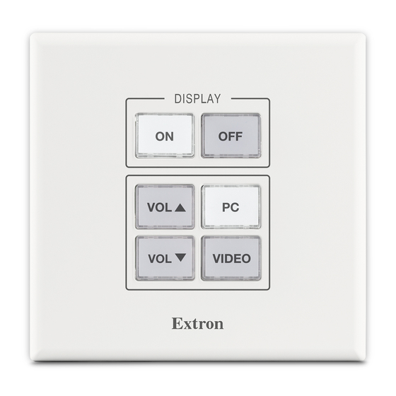
Operation This section of the guide covers the following topics: Front Panel Features • — Locations and descriptions of items on the front panel • Reset Features and Resetting the Unit — Locations of the reset button and LED and information about the available reset modes and how to reset the MLC Plus 50/100/200 Front Panel Features Some features and indications are described in... - Page 37 A A A B B B (x4) DISPLAY Display Power Buttons C C C Function Buttons D D D VIDEO VIDEO RESET F F F Extron MLC Plus 50 Front Panel MLC Plus 50 Front Panel With Faceplate Without Faceplate Figure 29.
-
Page 38: Faceplates
A A A Display DISPLAY Power Buttons LAPTOP C C C Function HDMI Buttons C C C VOLUME VOLUME SCREEN E E E SCREEN MUTE DOWN Extron MLC Plus 200 Front Panel With Faceplate Figure 31. MLC Plus 200 Front Panel With Faceplate B B B (x6) Display... -
Page 39: Buttons
Buttons Buttons — All buttons are backlit so they are visible in low light conditions. By default, the active (selected) buttons light brighter than inactive buttons. The light intensity and blink rate can be set during configuration. Each button can be configured with a variety of commands and functions, as desired. - Page 40 Increment/decrement volume adjustment If the MLC Plus is configured for increment/decrement volume adjustment, typically you would configure the Volume LEDs to be off except during adjustment. In the most common configuration, when the volume is adjusted, the LEDs light briefly in a scrolling pattern to the top (increment) or bottom (decrement), as shown in the following examples.
-
Page 41: Reset Features And Resetting The Unit
Reset Features and Resetting the Unit Locating the Reset Button and LED Reset button and LED — Pressing this button causes various IP functions and Ethernet connection settings to be reset to the factory defaults. The adjacent green LED flashes depending on the selected reset mode (see RESET “Resetting the Unit”... - Page 42 MLC Plus 50/100/200 Series Controller Reset Mode Summary Use This Activation Result Mode to... Recover For devices with a firmware version below 2.00.0001 project To start the Project Recovery reset mode and recover a project: Project Recovery mode stops regular configuration operation and allows a connection to be and program On the PC, open Global Configurator.
- Page 43 MLC Plus 50/100/200 Series Controller Reset Mode Summary Use This Activation Result Mode to... Toggle stop/ To stop or start a program: The LED blinks 2 times if the program is • start program starting. Hold down the Reset button for about 3 seconds, until the The LED blinks 3 times if the program is Reset LED blinks once.
-
Page 44: Software-Based Configuration And Control
Software-based Configuration and Control This section of the guide is divided into the following topics: • Configuration and Control: an Overview • Basic Setup Steps: a Guide to this Section and Other Resources • Downloading the Software and Getting Started •... -
Page 45: Basic Setup Steps: A Guide To This Section And Other Resources
Basic Setup Steps: a Guide to this Section and Other Resources Prepare the installation site. NOTE: GC projects can be created offline and uploaded to the hardware at a later date. Change buttons or faceplates, if desired Hardware Features and Installation Follow the steps in starting on page 9. -
Page 46: Locating Software, Firmware, And Driver Files On The Extron Website
Locating Software, Firmware, and Driver Files on the Extron Website There are three main ways to find software, firmware, and device drivers within www.extron.com: • Via links from the web page for the specific product Download • Via the page (Click on the Download tab at the top of any page within the Extron website.) •... -
Page 47: Obtaining Control Drivers
To download a single driver rather than the package, click on the appropriate link in the row for the product you want to control to download the driver or to download the “communication sheet.” The communication sheet provides details that may be helpful for working with the product and its control driver. -
Page 48: Using Gc: Helpful Tips
Using GC: Helpful Tips Resources and Notes • The MLC Plus 50/100/200 Setup Guide ships with the units. It includes a quick reference to the front and rear panel features, and covers basic hardware installation. • Front Panel Features on page 28 and Rear and Side Panel Features and Cabling on page 16 in the “Hardware Features and Installation”... - Page 49 Data connections Check the cabling connections (see Rear and Side Panel Features and Cabling starting on page 16) and make adjustments as needed. The Link LEDs on the MLC Plus and on the PC should be lit solid green if a network connection is detected. If these LEDs are not lit, either the cable is faulty or not plugged in, or the wrong type of LAN (Ethernet) and PoE port and LEDs cable is being used (see...
-
Page 50: Reference Information
Reference Information This section of the guide includes the following reference items: Network Port Requirements and Licensed Third‑Party Software • • File Types: a Key to Extron‑specific File Names • Secure Sockets Layer (SSL) Certificates Full product specifications are available via the MLC Plus 50/100/200 product pages at www.extron.com. -
Page 51: Secure Sockets Layer (Ssl) Certificates
Secure Sockets Layer (SSL) Certificates Extron controllers ship with factory-installed SSL certificates created by Extron. If you want or are required to use a different SSL certificate at your installation site, then you can use system utilities in the Toolbelt software to change the SSL certificate at any time. The Toolbelt Help File provides instructions on how to apply an SSL certificate to a controller. -
Page 52: Firmware Updates
Firmware Updates If the need arises, you can replace the MLC Plus firmware. This section covers the following firmware-related topics: • Determining the Firmware Version • Updating the Firmware Determining the Firmware Version There are several ways to check which version of firmware the controller is using: •... -
Page 53: Updating The Firmware
Updating the Firmware Firmware upgrade tools require the PC and the controller to both be connected to an Ethernet network. The instructions for each method of updating the MLC Plus firmware assume you have installed the appropriate software on your PC first. NOTES: •... - Page 54 Glossary 10/100Base‑T Ethernet which uses unshielded twisted pair (UTP - CAT 5, CAT 5e, CAT 6) cable, where the amount of data transmitted between two points in a given amount of time is equal to either 10 Mbps or 100 Mbps. 1000Base‑T, gigabit Ethernet An Ethernet standard that transmits at 1 Gbps over twisted pair wire.
- Page 55 IP address A unique, 32-bit, binary number (12 digit decimal number, xxx.xxx.xxx.xxx) that identifies each device or device port (an information sender and/or receiver) that is connected to static IP) or dynamic (see a LAN, WAN, or the Internet. IP addresses can be static (see DHCP).
- Page 56 TCP (Transmission Control Protocol) A connection-oriented protocol at the Transport layer of the Open Systems Interconnection (OSI, ISO/IEC 7498-1) reference model. It provides reliable end-to-end data delivery from one network device to another. TCP/IP (Transmission Control Protocol/Internet Protocol) The communication protocol of the Internet. Computers and devices with direct access to the Internet are provided with a copy of the TCP/IP program to allow them to send and receive information in an understandable form.
- Page 57 Index Americans with Disabilities Act (ADA) file type names and descriptions LAN (IP) ports compliance 11 .eff 42 default settings 18 application diagram .eir 42 used for power over Ethernet system connections 5 .pkp 42 (PoE) 17 firmware latching determining the firmware relay description and wiring 23 version 44 .eff file 42...
- Page 58 serial communication protocol troubleshooting 40 updating the firmware 45 COM port defaults 19 data connections 41 username serial ports device control connections and default 18 wiring COM ports 19 configuration 41 STP 20-2P cable diagram and power connections 40 tip 19 subnet default value 18 definition of subnet mask 47...
- Page 59 Extron Electronics makes no further warranties either expressed or implied with respect to the product and its quality, performance, merchantability, or fitness for any particular use. In no event will Extron Electronics be liable for direct, indirect, or consequential damages resulting from any defect in this product even if Extron Electronics has been advised of such damage.
Need help?
Do you have a question about the MediaLink MLC Plus 50 and is the answer not in the manual?
Questions and answers