Table of Contents
Advertisement
Quick Links
Download this manual
See also:
User Manual
MLC Plus 50/100/200 Series • Setup Guide
The Extron MLC Plus 50/100/200 Series MediaLink
connection into AV systems to allow users to remotely control, monitor, and troubleshoot AV equipment,
A Y
P L
D I S
F
including display devices and switchers. Each controller includes an embedded web server and support
O F
O N
for Power over Ethernet (PoE). It also includes ports for bidirectional serial control, IR output, relays, digital
P C
L
V O
input, and (except for the MLC Plus 50) volume control. Each MLC Plus is shipped with a mud ring.
E O
V I D
L
V O
n
t r o
E x
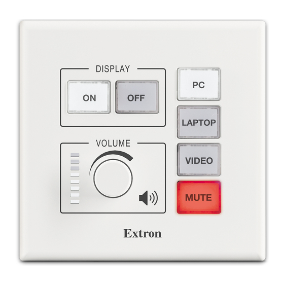
MLC Plus 50
O P
F
P T
O F
L A
O N
E O
V I D
T E
M U
n
n
t r o
t r o
E x
E x
MLC Plus 100
A
V G
F
O F
C
D O
M
O N
C A
T E
M U
n
n
t r o
t r o
E x
E x
MLC Plus 200
Installation
Step 1: Get Ready
Use the following check list to prepare for the installation.
…
Download and install the latest version of the following:
Global Configurator Professional or Global Configurator Plus software — for setting up and configuring the controller.
•
GC includes a link to the Toolbelt software and a way to upgrade the firmware of the controller. You must have an Extron
Insider account to use GC software. Contact an Extron support representative regarding training to use the full features
of GC Professional (see
Toolbelt software — for setting up and configuring the controller
•
IP Link Pro device drivers — for use with GC (Professional or Plus), to make control of other devices possible.
•
All are avail able from
…
Obtain network information for the unit from the network administrator. You will need the following details for each MLC Plus
device:
…
DHCP setting (on or off)
…
Device (MLC Plus) IP address
…
Write down the MAC address of each IP Link Pro device (such as the MLC Plus 50/100/200) to be used.
…
Obtain model names and setup information for devices the MLC Plus 50/100/200 will control.
Step 2: Prepare the Installation Site
ATTENTION:
Installation and service must be performed by authorized personnel only.
•
L'installation et l'entretien doivent être effectués uniquement par un technicien qualifié.
•
Extron recommends installing the MLC Plus into a grounded, UL Listed electrical junction box.
•
Extron recommande d'installer le MLC Plus dans un boîtier d'encastrement électrique mis à la terre, certifié UL.
•
A Y
A Y
P L
P L
D I S
D I S
D I S
MLC Plus 100 AAP
O P
P T
L A
M I
M
H D
H D
F
O F
O N
T E
M U
MLC Plus 200 AAP
Locating Software, Firmware, and Driver Files on the Extron Website
www.extron.com
(see
Locating Software, Firmware, and Driver Files on the Extron Website
Controllers with IP Link
®
All models fit standard US junction boxes or mud rings.
•
The MLC Plus 100 AAP and MLC Plus 200 AAP
•
also include space to mount from one to four
Extron AAP plates.
This guide provides instructions for an experienced
installer to install an MLC Plus Series controller and to
create a basic configuration. Configure the controller
using Extron Global Configurator
in Global Configurator Professional (GC Professional)
or Global Configurator Plus (GC Plus) mode. The MLC
integrates with Extron GlobalViewer
software and the GlobalViewer web-based AV resource
management for remote control applications. Global
Configurator and other useful software applications are
available at www.extron.com.
…
Subnet mask
…
Gateway IP address
Pro integrate Ethernet
®
(GC) software running
®
Enterprise (GVE)
®
on page 12).
on page 12).
…
User name
…
Passwords
1
Advertisement
Table of Contents

Related Manuals for Extron electronics MLC Plus 50


Summary of Contents for Extron electronics MLC Plus 50
- Page 1 Each controller includes an embedded web server and support for Power over Ethernet (PoE). It also includes ports for bidirectional serial control, IR output, relays, digital input, and (except for the MLC Plus 50) volume control. Each MLC Plus is shipped with a mud ring. V I D All models fit standard US junction boxes or mud rings.
-
Page 2: Americans With Disabilities Act (Ada) Compliance
MLC Plus 50/100/200 Series • Setup Guide (Continued) ATTENTION: If the controller will be installed into fine furniture, it is best to hire a licenced, bonded craftsperson to cut the access • hole and perform the physical installation so the surface will not be damaged. -
Page 3: Replacing Button Labels
Replacing button labels You may wish to customize the button labels. The labels can be changed at any time. Follow these steps to change the translucent button labels: Remove the faceplate as mentioned in step 1 of Replacing a faceplate. For each button label to be replaced, use the provided Extron removal tool to gently separate the clear button cap (lens) from its white diffuser backing as follows: insert the end of the... -
Page 4: Front Panel Features
MLC Plus 50/100/200 Series • Setup Guide (Continued) Front panel features Faceplate Mounting Holes (x4) DISPLAY Display Power Buttons Function Buttons Reset LED and VIDEO Button VIDEO RESET Address Extron MLC Plus 50 Front Panel MLC Plus 50 Front Panel With Faceplate... -
Page 5: Rear And Side Panel Features
MLC Plus 100 represents all of those models. The rear panel of the MLC Plus 50 has one COM port instead of two, and does not have a volume control port, but it is otherwise the same as the other models. MLC Plus 50 Rear Panel Power... -
Page 6: Control, Bidirectional - Serial (Com)
MLC Plus 50/100/200 Series • Setup Guide (Continued) Control and power — LAN (Ethernet) and PoE Activity LED: Blinks yellow to indicate data is being sent or received. LAN/PoE (Ethernet and Power Over Ethernet) Connect to an Ethernet network. NOTE:... -
Page 7: Control - Digital Input
Control — digital input Control — relay All relays are normally open. Digital Input Rear Rear Panel Panel Con gure the port with or without Relays +5 VDC pull-up. • Connect devices for relay control. Use this port to: • Do not exceed a total of 24 V, 1 A •... -
Page 8: Step 7: Test And Troubleshoot
MLC Plus 50/100/200 Series • Setup Guide (Continued) Step 5: Set up the MLC Plus for Network Communication Connect the PC that you will use for setup and the MLC Plus MLC Plus to the same Ethernet subnetwork. For LAN Network Communication Setup Control and power —... - Page 9 Place the AAP opening of the MLC Plus faceplate over the cluster of AAPs to check for correct fit. Make sure that the • edges of the AAPs all fit within the faceplate AAP opening so that no edges or corners catch or prevent the faceplate from laying flat against the AAP mounting bracket.
- Page 10 MLC Plus 50/100/200 Series • Setup Guide (Continued) For non-AAP models, secure the MLC Plus to the junction box, wall or surface mounting box, or mud ring as follows (see figures 8 and 9): Insert the included screws through the oval slots at the top and bottom of the MLC Plus, through the plastic...
-
Page 11: Reset Modes: A Brief Summary
Reset button within 1 second. Use this mode to return the controller to factory default settings. For detailed information on each mode and its use, see the MLC Plus 50/100/200 Series User Guide at www.extron.com. About Global Configurator (with GC Professional and GC Plus Modes) What the Software Does Global Configurator Professional or Plus is the software tool for network setup and configuration of a MediaLink Plus controller. -
Page 12: Locating Software, Firmware, And Driver Files On The Extron Website
Extron S3 Sales & Technical Support Hotline or the Extron S3 Control Systems Support Hotline (1.800.633.9877). 68-2806-50 Rev. B www.extron.com © 2015 - 2018 Extron Electronics All rights reserved. All trademarks mentioned are the property of their respective owners. 03 18...
Need help?
Do you have a question about the MLC Plus 50 and is the answer not in the manual?
Questions and answers