Extron electronics MLC Plus 100 Series Setup Manual
Hide thumbs
Also See for MLC Plus 100 Series:
- User manual (59 pages) ,
- Setup manual (13 pages) ,
- Quick reference (2 pages)
Table of Contents
Advertisement
MLC Plus 50/100/200 Series • Setup Guide
The Extron MLC Plus 50/100/200 Series MediaLink
connection into AV systems. This allows users to remotely control, monitor, and troubleshoot AV equipment,
A Y
P L
D I S
F
including display devices and switchers. Each controller includes an embedded web server and support
O F
O N
for Power over Ethernet (PoE). It also includes ports for bidirectional serial control, IR output, relays, digital
P C
L
V O
input, and (except for the MLC Plus 50) volume control. Each MLC Plus is shipped with a mud ring.
E O
V I D
L
V O
n
t r o
E x
MLC Plus 50
P C
A Y
P L
D I S
O P
F
P T
O F
L A
O N
E O
V I D
M E
L U
V O
T E
M U
n
t r o
E x
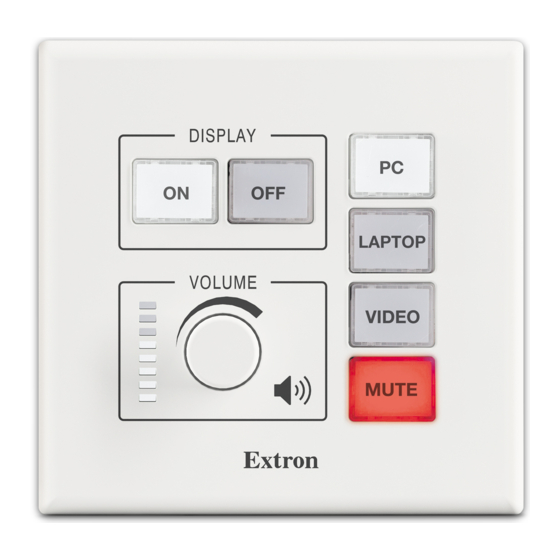
MLC Plus 100
O P
P T
L A
P C
M I
H D
A Y
A
P L
V G
E N
D I S
R E
S C
F
O F
U P
C
D O
E N
M
O N
C A
R E
S C
W N
D O
T E
M E
M U
L U
V O
n
t r o
E x
MLC Plus 200
Installation
Step 1: Get Ready
Use the following check list to prepare for the installation.
•
Download and install the latest version of the following:
•
Global Configurator Professional or Global Configurator Plus software — for setting up and configuring the controller.
GC includes a link to the Toolbelt software and a way to upgrade the firmware of the controller. You must have an Extron
Insider account to use GC software. Contact an Extron support representative regarding training to use the full features
of GC Professional (see
•
Toolbelt software — for setting up and configuring the controller
•
IP Link Pro device drivers — for use with GC (Professional or Plus), to make control of other devices possible.
All are avail able from
•
Obtain network information for the unit from the network administrator. You will need the following details for each MLC Plus device:
•
DHCP setting (on or off)
•
Device (MLC Plus) IP address
•
Write down the MAC address of each IP Link Pro device (such as the MLC Plus 50/100/200) to be used.
•
Obtain model names and setup information for devices the MLC Plus 50/100/200 will control.
•
Each controller comes with a factory-installed Secure Sockets Layer (SSL) security certificate. If you intend to install a
different SSL certificate, contact your IT department to obtain the certificate or for instructions on how to obtain one. See
"Secure Sockets Layer (SSL) Certificates" in the MLC Plus 50/100/200 Series User Guide for requirements and guidelines
regarding SSL certificates. IEEE 802.1X authentication is also supported once enabled (see "IEEE 802.1X Certificates" in the
MLC Plus 50/100/200 Series User Guide for details).
P C
A Y
P L
D I S
O P
F
P T
O F
L A
O N
E O
V I D
M E
L U
V O
T E
M U
n
t r o
E x
MLC Plus 100 AAP
O P
P T
L A
P C
M I
H D
A Y
A
P L
V G
E N
D I S
R E
S C
F
O F
U P
C
D O
E N
M
O N
C A
R E
S C
W N
D O
M E
T E
L U
M U
V O
MLC Plus 200 AAP
Locating Software, Firmware, and Driver Files on the Extron Website
www.extron.com
Locating Software, Firmware, and Driver Files on the Extron Website
(see
Controllers with IP Link
®
•
All models fit standard US junction boxes or mud rings.
•
The MLC Plus 100 AAP and MLC Plus 200 AAP
also include space to mount from one to four
Extron AAP plates.
This guide provides instructions to install an
MLC Plus Series controller and to create a basic
configuration. Configure the controller using Extron
Global Configurator
Global Configurator Professional (GC Professional) or
Global Configurator Plus (GC Plus) mode. The MLC
integrates with Extron GlobalViewer
software and the GlobalViewer web-based AV resource
management for remote control applications. Global
Configurator and other useful software applications are
available at www.extron.com.
•
Subnet mask
•
Gateway IP address
Pro integrate Ethernet
®
(GC) software running in
®
Enterprise (GVE)
®
on page 11).
on page 11).
•
User name
•
Passwords
1
Advertisement
Table of Contents

Related Manuals for Extron electronics MLC Plus 100 Series


Summary of Contents for Extron electronics MLC Plus 100 Series
- Page 1 MLC Plus 50/100/200 Series • Setup Guide The Extron MLC Plus 50/100/200 Series MediaLink Controllers with IP Link Pro integrate Ethernet ® ® connection into AV systems. This allows users to remotely control, monitor, and troubleshoot AV equipment, D I S including display devices and switchers. Each controller includes an embedded web server and support for Power over Ethernet (PoE).
-
Page 2: Step 2: Prepare The Installation Site
MLC Plus 50/100/200 Series • Setup Guide (Continued) Step 2: Prepare the Installation Site ATTENTION: • Installation and service must be performed by authorized personnel only. • L’installation et l’entretien doivent être effectués uniquement par un technicien qualifié. • Extron recommends installing the MLC Plus into a grounded, UL Listed electrical junction box. •... -
Page 3: Replacing Button Labels
Align the openings of the new faceplate with the buttons and knob and with the LEDs and place the faceplate against the unit. The magnetic catches fasten the faceplate onto the unit. TIP: You can wait until the unit is mounted to the junction box or mud ring before placing the new faceplate on the unit. Replacing button labels You may wish to customize the button labels. -
Page 4: Front Panel Features
MLC Plus 50/100/200 Series • Setup Guide (Continued) Front panel features Faceplate Mounting Holes (x4) DISPLAY Display Power Buttons Function Buttons Reset LED and VIDEO Button VIDEO RESET Address Extron MLC Plus 50 Front Panel MLC Plus 50 Front Panel With Faceplate Without Faceplate Faceplate Mounting Holes (x4) -
Page 5: Rear And Side Panel Features
(Ethernet) connector and LEDs Grounding screw MLC Plus 50 Rear and side panel features Right Side NOTE: For rear panel features and cabling, the MLC Plus 100, MLC Plus 100 AAP, MLC Plus 200, and MLC Plus 200 AAP are identical, so in this section the MLC Plus 100 represents all of those models. The rear panel of the MLC Plus 50 has one MLC Plus 50 Rear Panel COM port instead of two, and does not have a volume control port, but it is otherwise the same as the other models. -
Page 6: Control And Power - Lan (Ethernet) And Poe
MLC Plus 50/100/200 Series • Setup Guide (Continued) Control and power — LAN (Ethernet) and PoE Activity LED: Blinks yellow to indicate data is being sent or received. LAN/PoE (Ethernet and Power Over Ethernet) Connect to an Ethernet network. This port must be con gured. Side Default protocol: NOTE:... -
Page 7: Control - Digital Input
Control — digital input Control — relay All relays are normally open. Digital Input Rear Rear Panel Panel Con gure the port with or without Relays +5 VDC pull-up. • Connect devices for relay control. Use this port to: • Do not exceed a total of 24 V, 1 A •... -
Page 8: Step 7: Test And Troubleshoot
MLC Plus 50/100/200 Series • Setup Guide (Continued) Step 5: Set up the MLC Plus for Network Communication Connect the PC that you will use for setup and the MLC Plus to Network Communication Setup the same Ethernet subnetwork. For LAN connections for the MLC, Control and power —... - Page 9 • Place the AAP opening of the MLC Plus faceplate over the cluster of AAPs to check for correct fit. Make sure that the edges of the AAPs all fit within the faceplate AAP opening so that no edges or corners catch or prevent the faceplate from laying flat against the AAP mounting bracket.
- Page 10 MLC Plus 50/100/200 Series • Setup Guide (Continued) For non-AAP models, secure the MLC Plus to the junction box, wall or surface mounting box, or mud ring as follows (see figures 8 and 9): Insert the included screws through the oval slots at the top and bottom of the Wall MLC Plus, through the plastic...
-
Page 11: Reset Modes: A Brief Summary
Reset Modes: a Brief Summary The MLC Plus controllers offer the following reset modes: • Use Factory Firmware: Press and hold the Reset button (located behind the faceplate) while applying power to the unit. Keep holding the button down until the Reset LED blinks twice, or for 6 seconds, then release the button. -
Page 12: Overall Configuration Procedure For The Controller
For information on safety guidelines, regulatory compliances, EMI/EMF compatibility, accessibility, and related topics, see the Extron Safety and Regulatory Compliance Guide on the Extron website. www.extron.com © 2015-2022 - Extron Electronics All rights reserved. 68-2806-50 All trademarks mentioned are the property of their respective owners. Rev. D Worldwide Headquarters: Extron USA West, 1025 E.
Need help?
Do you have a question about the MLC Plus 100 Series and is the answer not in the manual?
Questions and answers