American Dynamics SpeedDome Ultra 8 Operator's Manual
Camera dome, configuration utility version 1.01
Hide thumbs
Also See for SpeedDome Ultra 8:
- Installation and service manual (72 pages) ,
- Configuration and user's manual (46 pages) ,
- Installation manual (42 pages)

Related Manuals for American Dynamics SpeedDome Ultra 8


Summary of Contents for American Dynamics SpeedDome Ultra 8
-
Page 1: Camera Dome
® SpeedDome Ultra 8 Camera Dome Configuration Utility Version 1.01 Operator’s Guide 8200-0600-01 B... - Page 3 ® SpeedDome Ultra 8 Camera Dome Configuration Utility Operator’s Guide Version – 1.08...
-
Page 4: Fcc Compliance
SOFTWARE LICENSE AGREEMENT A Software License Agreement appears in Appendix H of this manual. Please read it carefully. Using the SpeedDome Ultra 8 Camera Dome Configuration Utility software indicates that you accept the terms and conditions of this agreement. NOTICE The information in this manual was current when published. -
Page 5: Table Of Contents
Displaying Direction Indicators ... 74 Configuring the Display of Name Information... 76 Assigning or Changing Name Information ... 77 Changing the Settings for Text Displayed On-Screen ... 79 SPEEDDOME ULTRA 8 CONFIGURATION UTILITY OPERATOR’S GUIDE 3 of 140 8200-0600-01, REV. B... - Page 6 Command Summary ... 103 Supported Controllers ... 105 Performance Notes... 105 Appendix C: Pelco Coaxitron and “P” Protocols Command Summary... 107 Supported SpeedDome Ultra 8 Camera Dome Features... 107 Pelco Command Summary... 107 Performance Notes... 108 Tested Pelco Equipment ... 109 Supported Pelco Features...
-
Page 7: Preface: Before You Begin
Preface: Before You Begin This preface provides important information that you should be familiar with before using the SpeedDome Ultra 8 camera dome. It includes a document overview, text conventions, a list of related documents, and how to obtain product help. -
Page 8: Text Conventions
Notes are separated by ruled lines. Notes call attention to any items that may be of special importance. Icons identify the type of note. SPEEDDOME ULTRA 8 CONFIGURATION UTILITY OPERATOR’S GUIDE Used for terms specific to the system, and text that requires special emphasis;... -
Page 9: Related Documents
Related Documents Other sources provide supplemental information about your SpeedDome Ultra 8 camera dome. These sources serve to enhance your understanding of the product and its use. • The SpeedDome Ultra 8 Camera Dome Configuration Utility Quick Reference Guide (8200-0600-02) provides a brief overview of how to use the configuration utility. - Page 10 SPEEDDOME ULTRA 8 CONFIGURATION UTILITY 8200-0600-01, REV. B 8 of 140 OPERATOR’S GUIDE...
-
Page 11: Chapter 1: Using The Dome Configuration Utility
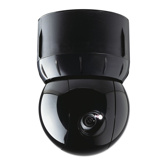
Chapter 1: Using the Dome Configuration Utility The SpeedDome Ultra 8 camera dome consists of a 35X or 22X optical zoom camera enclosed in compact dome housing. The 35X camera provides a black-and-white mode to enhance images obtained under low lighting conditions. The 35X camera also supports Wide Dynamic Range (WDR), which improves video performance under simultaneous indoor and outdoor lighting conditions, such as looking through an open door or window. -
Page 12: Working With The Dome Configuration Utility
During naming, move the cursor to the left of the current character in the name. Save changes and exit the utility from any screen. SPEEDDOME ULTRA 8 CONFIGURATION UTILITY OPERATOR’S GUIDE Figure 1. Dome Configuration Menu DOME CONFIGURATION MENU... -
Page 13: Entering The Dome's Password
If you forget the password, contact your Sales Representative for assistance. For information about programming and enabling password protection, see Chapter 6: Configuring Language and Password Settings on page 83. SPEEDDOME ULTRA 8 CONFIGURATION UTILITY OPERATOR’S GUIDE Figure 2. Enter Password screen... -
Page 14: Restoring Factory Settings
• To keep the changes, select No. If you choose No, the Dome Configuration Menu is displayed. Press Focus to accept the displayed option. SPEEDDOME ULTRA 8 CONFIGURATION UTILITY OPERATOR’S GUIDE Reset to Factory Settings Data Not Saved, Quit Anyway? 12 of 140 8200-0600-01, REV. -
Page 15: Accessing The Directset Menu
Dome Configuration Menu: Area Boundaries and AGC/Shutter Limit. Accessing the DirectSet Menu The DirectSet Menu provides easy access to commonly used SpeedDome Ultra 8 camera dome features when used with compatible controllers. This allows you to change or activate features without starting the dome configuration menu. - Page 16 58 SEQUENCE 59 SEQUENCE 60 SEQUENCE 10 61 SEQUENCE 11 62 SEQUENCE 12 63 SEQUENCE 13 64 SEQUENCE 14 65 SEQUENCE 15 66 SEQUENCE 16 FOCUS NEAR=previous page SPEEDDOME ULTRA 8 CONFIGURATION UTILITY OPERATOR’S GUIDE 14 of 140 8200-0600-01, REV. B...
- Page 17 62 SEQUENCE 12 63 SEQUENCE 13 64 SEQUENCE 14 65 SEQUENCE 15 Use FOCUS to select page SPEEDDOME ULTRA 8 CONFIGURATION UTILITY OPERATOR’S GUIDE 0 TOGGLE DIRECT SET MENU 1 DOME CONFIG MENU 2 AUTO IRIS & AUTO FOCUS 3 FLIP...
- Page 18 4+ DirectSet 5+ DirectSet 6+ DirectSet 7+ DirectSet 10+ DirectSet 11+ DirectSet SPEEDDOME ULTRA 8 CONFIGURATION UTILITY OPERATOR’S GUIDE Table 2. DirectSet commands Description (35X/22X) Toggle DirectSet Menu: Toggles between displaying and hiding the DirectSet menu. (35X/22X) Dome Config Menu: Displays the SpeedDome Ultra configuration menu.
- Page 19 56+ DirectSet 57+ DirectSet 58+ DirectSet 59+ DirectSet 60+ DirectSet 61+ DirectSet SPEEDDOME ULTRA 8 CONFIGURATION UTILITY OPERATOR’S GUIDE Description (35X) Auto Day/Night Mode: Resumes the most recently selected automatic IR mode setting. • Auto High: B/W mode activates ~30 lux.
-
Page 20: Keeping Records For The Dome's Settings
Refer to your controller instructions to determine if the DirectSet Menu is supported. Keeping Records for the Dome's Settings Keep records for each SpeedDome Ultra 8 camera dome installed at your facility. Appendix G: Dome Configuration Records summarizes the default values for each configuration setting. -
Page 21: Chapter 2: Configuring Pan, Tilt, Zoom, And Synchronization Options
Once the tilt control is released, the dome resumes normal operation. The dome is initially installed with the automatic flip feature disabled. In this situation, the dome stops when the tilt down reaches its lower limit. SPEEDDOME ULTRA 8 CONFIGURATION UTILITY OPERATOR’S GUIDE Figure 11. Pan/Tilt/Zoom/Sync Options screen... -
Page 22: Adjusting The Zoom Stop Settings
22X Camera Dome The SpeedDome Ultra 8 22X camera dome includes a 22X optical zoom camera with 11X digital zoom capability. The maximum possible zoom is 242X. The following example explains how 22X camera zoom stop settings work. - Page 23 6. Select Exit. The Dome Configuration Menu appears. 35X Camera Dome The SpeedDome Ultra 8 35X camera dome includes a 35X optical zoom camera with 12X digital zoom capability. The maximum possible zoom is 420X. The following example explains how 35X camera zoom stop settings work.
-
Page 24: Configuring The Line Lock Setting
For example, if the dome is installed in a lobby of a busy building, you may want to program presets that show different areas in the lobby. Figure 12 shows a sample floor plan for the lobby. SPEEDDOME ULTRA 8 CONFIGURATION UTILITY OPERATOR’S GUIDE 22 of 140... - Page 25 Select Off to disable Freeze Frame. This displays the dome motion and lens adjustments when presets or patterns are selected. The default setting is Off. 3. Select Exit. The Dome Configuration Menu appears. SPEEDDOME ULTRA 8 CONFIGURATION UTILITY OPERATOR’S GUIDE Figure 12. Lobby Floor Plan Waiting...
-
Page 26: Return To Auto After Calling A Preset
Follow the steps below to program Return to Auto: 1. Access the Dome Configuration Menu by pressing Iris Open, Focus Far, and Zoom Out on your controller. SPEEDDOME ULTRA 8 CONFIGURATION UTILITY OPERATOR’S GUIDE This information also applies if you attempt to rapidly call up a series of –... - Page 27 The Pan / Tilt / Zoom / Sync Opts screen appears. 3. Use the joystick to highlight Return to Auto, and press Focus Far to select. The Return to Auto screen appears. SPEEDDOME ULTRA 8 CONFIGURATION UTILITY OPERATOR’S GUIDE Figure 14. Pan/Tilt/Zoom/Sync Options screen...
- Page 28 Dome Configuration Menu, highlight Exit and Save Changes, and press Focus Far. Note: To Auto screen. SPEEDDOME ULTRA 8 CONFIGURATION UTILITY OPERATOR’S GUIDE The EIS, WDR, and IR mode features are only available on 35X camera Figure 16. Return to Auto screen (22X)
-
Page 29: Chapter 3: Configuring Camera Features
When Camera Functions is selected from the Dome Configuration Menu, one of the following screens appears: SPEEDDOME ULTRA 8 CONFIGURATION UTILITY OPERATOR’S GUIDE The IR mode, WDR, and EIS features are only available on 35X camera Figure 17. Camera Functions screen (35X) -
Page 30: Adjusting White Balance Settings
Blue Minimum As the value for the red setting increases, the image appears more red. As the value decreases, the image appears less red. SPEEDDOME ULTRA 8 CONFIGURATION UTILITY OPERATOR’S GUIDE Figure 19. White Balance color relationships WHITE BALANCE On-screen Color... -
Page 31: Understanding How Ir (Black & White) Mode Operates
Understanding How IR (Black & White) Mode Operates Note: The SpeedDome Ultra 8 camera dome provides a black-and-white (B/W) mode to improve camera performance when the light level falls below certain thresholds. This allows clear images to be obtained under low-light conditions. This is referred to as IR Mode. There are SPEEDDOME ULTRA 8 CONFIGURATION UTILITY OPERATOR’S GUIDE... - Page 32 • To change the mode using Manchester protocol: enter 68, and then press Call Preset. Using the manual command has the following affect on the menu settings: SPEEDDOME ULTRA 8 CONFIGURATION UTILITY OPERATOR’S GUIDE Table 3. IR Mode parameters Camera Performance...
-
Page 33: Understanding Wide Dynamic Range
When the door is open, additional light from outside enters the room and distortion occurs. Without WDR, you could adjust the iris of the camera to compensate for the lighting change; SPEEDDOME ULTRA 8 CONFIGURATION UTILITY OPERATOR’S GUIDE Table 4. IR Mode menu settings The Wide Dynamic Range feature is only available on 35X camera domes. - Page 34 With WDR enabled, you can see the scenes both inside and outside the loading dock area. In Figure 23, you can see the boxes stacked inside the loading dock area and the car approaching the door. SPEEDDOME ULTRA 8 CONFIGURATION UTILITY OPERATOR’S GUIDE 32 of 140...
-
Page 35: Working With Agc And Open Shutter Settings
Working with AGC and Open Shutter Settings The SpeedDome Ultra 8 camera dome provides settings for compensating for low-light scenes in color: Automatic Gain Control and Open Shutter. Automatic Gain Control (AGC) amplifies the video signal in scenes with minimal light. Many low-light scenes result in picture noise. As gain is increased, the picture noise is also amplified. - Page 36 If the light were to change from red to green halfway through the field integration interval (125 milliseconds), it may appear that both the red and green lights are on simultaneously. This situation is illustrated in Figure 25. SPEEDDOME ULTRA 8 CONFIGURATION UTILITY OPERATOR’S GUIDE Figure 24. Graphical view of Shutter Limit settings...
- Page 37 • For 22X cameras, the setting values range from 0 to 28dB. • For 35X cameras, the setting values range from 10 to 32dB. SPEEDDOME ULTRA 8 CONFIGURATION UTILITY OPERATOR’S GUIDE Figure 25. Mixed field integration Red Light Red/Green Light...
-
Page 38: Setting Up Electronic Image Stabilization (Eis)
Zoom Out on your controller. 2. Use the joystick to highlight Camera Functions and press Focus Far to select. The Camera Functions screen (Figure 27) appears. SPEEDDOME ULTRA 8 CONFIGURATION UTILITY OPERATOR’S GUIDE The EIS feature is only available on 35X camera domes. -
Page 39: Camera Functions
5 Hz = Designed to stabilize the dome when unwanted dome movements are at 5 Hz. • Off = Turns off Electronic Image Stabilization. Note: appear on the Camera Functions screen. SPEEDDOME ULTRA 8 CONFIGURATION UTILITY OPERATOR’S GUIDE Figure 27. Camera Functions screen CAMERA FUNCTIONS Auto White Bal... - Page 40 SPEEDDOME ULTRA 8 CONFIGURATION UTILITY 8200-0600-01, REV. B 38 of 140 OPERATOR’S GUIDE...
-
Page 41: Chapter 4: Configuring Alarms, Areas, Home, Privacy Settings, Presets And Scan Limits
• To change the settings, move the highlight bar to appropriate field and make the changes. • To return to the Dome Configuration Menu, select Exit. SPEEDDOME ULTRA 8 CONFIGURATION UTILITY OPERATOR’S GUIDE Figure 28. Alarms/Areas/Home/Presets/PZ screen ALARMS/AREAS/HOME/PRESETS/PZ SET ALARM ACTIONS... -
Page 42: Configuring Alarm Actions
Note: “normal.” A manual reset is not available. SPEEDDOME ULTRA 8 CONFIGURATION UTILITY OPERATOR’S GUIDE Figure 29. Set Alarm Actions screen SET ALARM ACTIONS... - Page 43 Choose No to prevent changes in the input states from being forwarded to the host controller. The default setting is Yes. 7. Select Exit to return to the Alarm/Areas/Home/PZ screen. SPEEDDOME ULTRA 8 CONFIGURATION UTILITY OPERATOR’S GUIDE Note: The protocol (or controller) used may support fewer presets. Refer to the appropriate Appendix for additional information.
-
Page 44: Configuring Normal Input States For Alarms
The normal state is used by both internal alarms and controller defined alarms. SPEEDDOME ULTRA 8 CONFIGURATION UTILITY OPERATOR’S GUIDE Figure 30. Set Alarm States screen... -
Page 45: Assigning The Dome's Home Position
To assign the home position, select Set Home Position from the Alarms/Areas/Home/Presets/PZ screen. The following screen (Figure 31) appears: SPEEDDOME ULTRA 8 CONFIGURATION UTILITY OPERATOR’S GUIDE In most cases, the normal input state for a dome's input should match the 43 of 140 8200-0600-01, REV. -
Page 46: Set Home Position
If the selected pattern is not programmed, the dome runs the Apple Peel pattern. • For output, select the number from 1 through 3 for the output you want to assign. Continue with step 5. SPEEDDOME ULTRA 8 CONFIGURATION UTILITY OPERATOR’S GUIDE Figure 31. Set Home Position screen SET HOME POSITION... -
Page 47: Setting The North Position
1. Select Alarms/Areas/Home/Presets/PZ from the Dome Configuration Menu. 2. Select Set North Position. The following screen (Figure 32) appears: SPEEDDOME ULTRA 8 CONFIGURATION UTILITY OPERATOR’S GUIDE If you selected a preset that has not been programmed, preset programming 45 of 140... -
Page 48: Programming Area Boundaries
Areas have been programmed around the fixtures in the room. As shown in this example, areas can be different sizes. SPEEDDOME ULTRA 8 CONFIGURATION UTILITY OPERATOR’S GUIDE Figure 32. Set North Position screen... - Page 49 Note: Instructions for assigning new names appear in Chapter 5: Configuring Text Displayed On-Screen on page 71. SPEEDDOME ULTRA 8 CONFIGURATION UTILITY OPERATOR’S GUIDE Figure 33. An example of areas found in a break room Start of Area 1/...
-
Page 50: Area Boundaries
See the note on page 5. Mark the end-point of the area. The area number automatically advances. 6. Repeat steps 4 and 5 for each area you want to establish. SPEEDDOME ULTRA 8 CONFIGURATION UTILITY OPERATOR’S GUIDE Figure 34. Area Boundaries screen AREA BOUNDARIES... -
Page 51: Establishing Privacy Zones
Zones are active. The menus change to one-sized text if Privacy Zones are hidden or deleted. To program Privacy Zones, select Privacy Zones from the Alarms/Areas/Home/Presets/ PZ screen. The following screen (Figure 35) appears: SPEEDDOME ULTRA 8 CONFIGURATION UTILITY OPERATOR’S GUIDE You will receive an error message under the following conditions:... -
Page 52: Privacy Zones
The dome’s firmware prevents you from establishing a zone that is too small or too large (greater than 90-degrees pan or tilt from the starting point). Figure 37 illustrates the Privacy Zone programming screen: SPEEDDOME ULTRA 8 CONFIGURATION UTILITY OPERATOR’S GUIDE Figure 35. Privacy Zones screen... - Page 53 To compensate for this limitation, you may want to program the Privacy Zone to be 20 to 25% larger than the area you want to mask. SPEEDDOME ULTRA 8 CONFIGURATION UTILITY OPERATOR’S GUIDE Figure 37. Privacy Zone Programming screen...
- Page 54 In this situation, the arrows blink because the target area is the same distance from all three zones. SPEEDDOME ULTRA 8 CONFIGURATION UTILITY OPERATOR’S GUIDE Remember, if the arrows are blinking, you are not in a valid target area.
- Page 55 1. Select Alarms/Areas/Home/Presets/PZ from the Dome Configuration Menu. 2. Select Privacy Zones. The Program Privacy Zones screen displays. 3. Select Delete All Zones. SPEEDDOME ULTRA 8 CONFIGURATION UTILITY OPERATOR’S GUIDE Figure 39. Deleting Privacy Zone – Valid Selection Zone 2...
-
Page 56: Programming Sequences
Follow the steps below to program Sequences. 1. Access the Dome Configuration Menu (Figure 40) by pressing Iris Open, Focus Far, and Zoom Out on your controller. SPEEDDOME ULTRA 8 CONFIGURATION UTILITY OPERATOR’S GUIDE YOU ARE ABOUT TO DELETE ALL PRIVACY ZONES... -
Page 57: Scan Limits
2. Highlight Alarms / Areas / Home / Presets / PZ and press Focus Far to select. The Alarms/Areas/Home/Presets/PZ screen appears. 3. Highlight Presets and press Focus Far. The Select Preset To Program screen (Figure 42) appears. SPEEDDOME ULTRA 8 CONFIGURATION UTILITY OPERATOR’S GUIDE Figure 40. Dome Configuration Menu screen DOME CONFIGURATION MENU... - Page 58 9. Highlight the Dwell Time Sec field and press Zoom In/Out until the number of seconds you want the Preset to remain on-screen appears (0-60 seconds in 10-second increments). SPEEDDOME ULTRA 8 CONFIGURATION UTILITY OPERATOR’S GUIDE Figure 42. Select Preset to Program screen...
-
Page 59: Dome Information
Zoom Out on your controller. 2. Highlight Alarms / Areas / Home / Presets / PZ and press Focus Far to select. The Alarms/Areas/Home/Presets/PZ screen (Figure 45) appears. SPEEDDOME ULTRA 8 CONFIGURATION UTILITY OPERATOR’S GUIDE Figure 44. Dome Configuration Menu screen... -
Page 60: Set Alarm Actions
(1-60 min.). This triggers the Sequence to run. 7. Highlight the Exit field and press Focus Far to select. 8. Continue to exit until the completely out of all programming menus. SPEEDDOME ULTRA 8 CONFIGURATION UTILITY OPERATOR’S GUIDE Figure 45. Alarms/Areas/Home/Presets/PZ screen ALARMS/AREAS/HOME/PRESETS/PZ... -
Page 61: Pattern Options-Fixed Or Variable Speed
Sequence will be interrupted. Pattern Options—Fixed or Variable Speed A Pattern is a series of programmed pan/tilt/zoom dome movements. The SpeedDome Ultra 8 camera dome allows you to create fixed speed or variable speed Patterns (variable speed Patterns are dependent on system capability). -
Page 62: Recording Patterns When Configured For 16
1. Enter the appropriate keyboard commands to record a Pattern, using 1, 2, or 3 as your Pattern number (consult your keyboard user guide for specific steps.). The Pattern Select screen (Figure 49) appears. SPEEDDOME ULTRA 8 CONFIGURATION UTILITY OPERATOR’S GUIDE Figure 48. On-Screen Text Display screen... -
Page 63: Changing Camera Functions Within Presets
When Presets are created, they adopt the dome parameters defined in the Camera Functions screen. You can now customize camera functions for each Preset by accessing the Camera Functions screen from the Presets screen. SPEEDDOME ULTRA 8 CONFIGURATION UTILITY OPERATOR’S GUIDE Figure 49. Pattern Select screen... - Page 64 2. Highlight Alarms / Areas / Home / Presets / PZ and press Focus Far to select. The Alarms / Areas / Home / Presets / PZ screen appears. SPEEDDOME ULTRA 8 CONFIGURATION UTILITY OPERATOR’S GUIDE If you change the parameters in the Camera Functions menu for an Figure 50.
- Page 65 4. Highlight the Preset Number field and press Zoom In/Out until your desired Preset number appears. 5. Highlight Camera Functions and press Focus Far. One of the following Camera Functions screens appears. SPEEDDOME ULTRA 8 CONFIGURATION UTILITY OPERATOR’S GUIDE Figure 52. Select Preset to Program screen SELECT PRESET TO PROGRAM...
-
Page 66: Establishing Scan Limits
By setting left and right scan limits where the building’s wall becomes visible, you ensure that only useful video of the parking lot is being observed when the scan is active. SPEEDDOME ULTRA 8 CONFIGURATION UTILITY OPERATOR’S GUIDE Figure 54. Camera Functions screen (22X camera dome) - Page 67 A stepped scan pans slowly, pausing briefly every 10° between the left and right scan limits. Once the right scan limit is reached, the scan reverses. Figure 56 illustrates the stepped scan. Each arrowhead represents a 10° step in the scan. SPEEDDOME ULTRA 8 CONFIGURATION UTILITY OPERATOR’S GUIDE Figure 55. Left and Right Scan Limits...
- Page 68 The DirectSet menu is not available for domes used with the Manchester protocol. 1. Select Alarms/Areas/Home/Presets/PZ from the Dome Configuration Menu. 2. Select Scan Limits. SPEEDDOME ULTRA 8 CONFIGURATION UTILITY OPERATOR’S GUIDE Figure 57. Random Scan Left Scan Limit...
-
Page 69: Ad Up-The-Coax Protocol
PAN to LEFT limit ZOOM to mark BOUNDARY Cancel RIGHT limit to Delete CANCEL Press Focus during steps 3 or 4 to cancel scan limit programming. At the time of publication, the following American Dynamics keyboards 67 of 140 8200-0600-01, REV. B... - Page 70 (Focus Far) (Focus Near) (Zoom In) or Twist joystick clockwise (Zoom Out) or Twist joystick counterclockwise SPEEDDOME ULTRA 8 CONFIGURATION UTILITY OPERATOR’S GUIDE Table 7. AD-UTC commands summary Function Start the configuration utility. Move the highlight bar on the active menu.
- Page 71 (Pattern) (Function+Focus Far) (Function+Focus Near) (Function+Iris Open) (Function+Iris Close) (Flip) SPEEDDOME ULTRA 8 CONFIGURATION UTILITY OPERATOR’S GUIDE Table 9. Additional dome commands Function Program selected Preset (Preset) Recall selected Preset (Ver. 0.20 keyboard only) Start selected Pattern programming (Ver. 0.20 keyboard only) Save Pattern programming (Ver.
- Page 72 Performance Notes Keep the following considerations in mind when using the SpeedDome Ultra 8 camera dome in the AD-UTC environment: Address Setting The camera dome must be set to address 891 to operate in the AD-UTC environment. When the dome initializes or resets, the address and protocol information (UTC_T) appear on-screen.
-
Page 73: Chapter 5: Configuring Text Displayed On-Screen
5 seconds. If “D” appears next to the zoom factor, the digital zoom is active (zooms greater than 22X). SPEEDDOME ULTRA 8 CONFIGURATION UTILITY OPERATOR’S GUIDE Figure 59. On-Screen Text Display... -
Page 74: Displaying Or Hiding All Name Information
When the display of camera or area names is enabled, the information appears on the screen continuously. Preset, pattern, and alarm names appear only while they are active. SPEEDDOME ULTRA 8 CONFIGURATION UTILITY OPERATOR’S GUIDE ZOOM X140D... -
Page 75: Displaying Diagnostic Tests During Reset
If you do not want diagnostic information to appear when the dome resets, a screen displaying the firmware version numbers for the Boot and Application code and the maximum optical zoom for the dome appears. SPEEDDOME ULTRA 8 CONFIGURATION UTILITY OPERATOR’S GUIDE CAMERA NAME... -
Page 76: Displaying Direction Indicators
Figure 62 illustrates the locations of the Direction Indicators on the display. Figure 62. Screen locations for Direction Indicators Tilt elevation/ declination from Horizontal SPEEDDOME ULTRA 8 CONFIGURATION UTILITY OPERATOR’S GUIDE 74 of 140 Pointing direction around the Pan axis (0–359°) - Page 77 25° below the virtual horizon. Panning to the left points the dome towards the South. Panning to the right points the dome towards the West. Figure 64. Pointing the dome precisely southwest with a tilt elevation of –25° SPEEDDOME ULTRA 8 CONFIGURATION UTILITY OPERATOR’S GUIDE 0°...
-
Page 78: Configuring The Display Of Name Information
3. Move the highlight bar to the item whose display setting you want to change. 4. Change the setting. • Choose On to display name information on the monitor. SPEEDDOME ULTRA 8 CONFIGURATION UTILITY OPERATOR’S GUIDE Figure 65. Name Configuration Menu NAME CONFIGURATION MENU... -
Page 79: Assigning Or Changing Name Information
• If you choose Camera Name, continue with step 6. • If you choose Area Name, Preset Name, Pattern Name, or Alarm Name, continue with step 4. SPEEDDOME ULTRA 8 CONFIGURATION UTILITY OPERATOR’S GUIDE RESET PROGRAMMABLE NAMES • • a-z (lower case) •... - Page 80 Focus to select it. If you make a mistake, Zoom In moves the cursor one space right, and Zoom Out moves the cursor one space left in the name. SPEEDDOME ULTRA 8 CONFIGURATION UTILITY OPERATOR’S GUIDE Figure 66. Select Name to Program screen...
-
Page 81: Changing The Settings For Text Displayed On-Screen
(slightly clear) or solid, with or without outlines. To change these settings, select Text Attribute Options from the On-Screen Text Display screen. The following screen appears: SPEEDDOME ULTRA 8 CONFIGURATION UTILITY OPERATOR’S GUIDE Figure 68. Text Attribute Options screen... - Page 82 If you want to change the text appearance for dome names and status information, move the highlight bar to Translucent Names. Continue with step 5. • If you are finished making changes, continue with step 6. SPEEDDOME ULTRA 8 CONFIGURATION UTILITY OPERATOR’S GUIDE Figure 69. Examples of text attributes 80 of 140...
- Page 83 Select 7 to display text associated with dome names and status information as solid (opaque). The default setting is 4. 6. Select Exit to return to the On-Screen Text Display screen. 7. Select Exit. The Dome Configuration Menu appears. SPEEDDOME ULTRA 8 CONFIGURATION UTILITY OPERATOR’S GUIDE 81 of 140 8200-0600-01, REV. B...
- Page 84 SPEEDDOME ULTRA 8 CONFIGURATION UTILITY 8200-0600-01, REV. B 82 of 140 OPERATOR’S GUIDE...
-
Page 85: Chapter 6: Configuring Language And Password Settings
Selecting a Language for Dome Messages and Prompts The dome supports menus, status information, and prompts in English, Spanish, French, German, Italian, and Portuguese. Note: English. SPEEDDOME ULTRA 8 CONFIGURATION UTILITY OPERATOR’S GUIDE Figure 70. Language / Password screen LANGUAGE / PASSWORD LANGUAGE SELECTION... -
Page 86: Language Selection
Focus Far. The following screen appears for a few seconds, and then the Language / Password screen appears in the newly selected language. SPEEDDOME ULTRA 8 CONFIGURATION UTILITY OPERATOR’S GUIDE Figure 71. Language Selection screen LANGUAGE SELECTION... -
Page 87: Setting And Enabling The Dome Password
Setting or Changing the Dome Password 1. Select Language/Password from the Dome Configuration Menu. 2. Select Set Password. The Set Password screen appears. SPEEDDOME ULTRA 8 CONFIGURATION UTILITY OPERATOR’S GUIDE Figure 72. Change Language screen Change Language Please Wait Changing the language does not alter any previously programmed names. - Page 88 Select ON to enable password protection. • Select OFF to disable password protection. The default setting is OFF. 4. Select Exit. The Dome Configuration Menu appears. Tip: SPEEDDOME ULTRA 8 CONFIGURATION UTILITY OPERATOR’S GUIDE Figure 73. Set Password screen SET PASSWORD PASSWORD: ******** ABCDEFGHIJKLMNOPQRST...
-
Page 89: Chapter 7: Displaying Dome Information
Base IO Control screens contain fields that can be changed. Figure 74. Dome Information screen–camera domes with outdoor IO boards Figure 75. Dome Information screen–camera domes with indoor IO boards SPEEDDOME ULTRA 8 CONFIGURATION UTILITY OPERATOR’S GUIDE DOME INFORMATION DOME MODEL... -
Page 90: Viewing Dome Model Information
Viewing Dome Model Information (All dome models) The Dome Model screen provides basic dome information that includes the dome model and type, mnemonic, software and FPGA versions, serial number, and manufacture date. SPEEDDOME ULTRA 8 CONFIGURATION UTILITY OPERATOR’S GUIDE DOME INFORMATION DOME MODEL... -
Page 91: Viewing Dome Operating Statistics
Dome Information screen. Viewing Dome Operating Statistics (All dome models) When Dome Statistics is selected from the Dome Information screen, the following information is displayed: SPEEDDOME ULTRA 8 CONFIGURATION UTILITY OPERATOR’S GUIDE Figure 77. Dome Model screen DOME MODEL NAME:... -
Page 92: Updating Io Board Flash Memory
(Indoor and outdoor domes only) When Init IO Flash is selected from the Dome Information screen, the following screen is displayed. It enables you to update the IO board flash memory. SPEEDDOME ULTRA 8 CONFIGURATION UTILITY OPERATOR’S GUIDE Table 10. Dome Statistics screen abbreviations Description Time moving right in seconds. -
Page 93: Using The Calibration Screen
SPEEDDOME ULTRA 8 CONFIGURATION UTILITY OPERATOR’S GUIDE This feature is only applicable to the Indoor Housing IO board (P/N Figure 80. - Page 94 (target), and then press Focus Far to set the calibration reference point. The Dome Information screen is then redisplayed. SPEEDDOME ULTRA 8 CONFIGURATION UTILITY OPERATOR’S GUIDE This feature is only applicable to the Indoor Housing IO board: Figure 81.
-
Page 95: Viewing Base Io Status Information
Note: 0311-0124-xx. When you are finished viewing the base IO status, select Exit to return to the Dome Information screen. SPEEDDOME ULTRA 8 CONFIGURATION UTILITY OPERATOR’S GUIDE Figure 82. Calibration screen Position Cross-hair To Target 1... -
Page 96: Working With The Base Io Control Screen
• If the dome address matches the IO base address, the dome performs the next verification step. SPEEDDOME ULTRA 8 CONFIGURATION UTILITY OPERATOR’S GUIDE This feature is only applicable to the Outdoor Housing IO board: P/N Figure 84. Base IO Control screen... - Page 97 FOCUS FAR. This deletes all presets, patterns, and other configurations that were stored in this IO base. A screen appears that indicates the base data is being cleared (Figure 87). SPEEDDOME ULTRA 8 CONFIGURATION UTILITY OPERATOR’S GUIDE Figure 85. Dome Address Changed screen...
- Page 98 IO base. If the data does not match, then the dome copies and uses the IO base data. The Restoring Dome Data screen (Figure 88) briefly appears. Note: the dome was powered down will reappear. SPEEDDOME ULTRA 8 CONFIGURATION UTILITY OPERATOR’S GUIDE Figure 87. Updating IO Base Memory screen Updating IO Base Memory! Please Wait! Figure 88.
-
Page 99: Appendix A: Sensornet And Rs-422 Command Summary
Save changes and exit the utility from any screen. Manually activate or deactivate IR mode. These commands not supported with MPLT with ADCC0200 or ADCC0300 controller. Refer to the appropriate operator’s manual for instructions. SPEEDDOME ULTRA 8 CONFIGURATION UTILITY OPERATOR’S GUIDE Use … Press and hold Iris Open,... -
Page 100: Supported Controllers And Matrix Switching Systems
Supported Controllers and Matrix Switching Systems This section provides information about the SensorNet and RS-422 controllers and matrix switchers that are compatible with the SpeedDome Ultra 8 camera dome. Refer to the controller information for details concerning specific functions supported. - Page 101 6 minutes 50 seconds. Total dome commands used in all patterns cannot exceed (3) Requires firmware version 0701-2833-0103 (EEPROM) / 0701-2834-0201 (Flash PROM) or newer. SPEEDDOME ULTRA 8 CONFIGURATION UTILITY OPERATOR’S GUIDE VM32/AD32 Supported Protocols Maximum Presets...
- Page 102 (5) Requires additional equipment to achieve these numbers. A dome address within each group of 64 or 99 cameras is reserved as a global broadcast address. SPEEDDOME ULTRA 8 CONFIGURATION UTILITY OPERATOR’S GUIDE AD168 Supported Protocols...
-
Page 103: Performance Notes
(3) Requires firmware 1.07 or newer and a compatible keyboard. Performance Notes The following considerations should be made when using the SpeedDome Ultra 8 camera dome in a SensorNet or RS-422 environment. Alarm Action Configuration The following controllers allow the alarm actions for domes to be specified at the controller: •... - Page 104 SPEEDDOME ULTRA 8 CONFIGURATION UTILITY 8200-0600-01, REV. B 102 of 140 OPERATOR’S GUIDE...
-
Page 105: Appendix B: Manchester Command Summary
Move the cursor to the right of the current character in the name or password. Move the cursor to the left of the current character in the name. SPEEDDOME ULTRA 8 CONFIGURATION UTILITY OPERATOR’S GUIDE 103 of 140 Use …... - Page 106 Run Pattern 1 Run Pattern 2 Run Pattern 3 This command changes the IR Mode setting on the Camera Functions menu. See Chapter 3 for information. SPEEDDOME ULTRA 8 CONFIGURATION UTILITY OPERATOR’S GUIDE 104 of 140 Use … 65 Set Preset...
-
Page 107: Supported Controllers
Contact your Sales Representative for current information. Performance Notes The following considerations should be made when using the SpeedDome Ultra 8 camera dome in a Manchester environment. Using Auxiliaries The dome provides four connections for auxiliaries. When used on a Manchester network, Auxiliaries 1 through 3 are supported. - Page 108 SPEEDDOME ULTRA 8 CONFIGURATION UTILITY 8200-0600-01, REV. B 106 of 140 OPERATOR’S GUIDE...
-
Page 109: Appendix C: Pelco Coaxitron And "P" Protocols Command Summary
Appendix C: Pelco Coaxitron and “P” Protocols Command Summary This appendix summarizes the SpeedDome Ultra 8 camera dome features that are supported by the Pelco Coaxitron and “P” protocols. In addition, it provides the controller commands used with the Configuration Utility. It also supplies information about tested Pelco equipment and supported Pelco features. -
Page 110: Performance Notes
Return to 0° pan Turn IR Mode On Turn IR Mode Off Reset Dome Performance Notes The following SpeedDome Ultra 8 camera dome features are not supported with the Pelco protocols: • PAL video format. This will be supported after further testing. •... -
Page 111: Tested Pelco Equipment
Tested Pelco Equipment The following Pelco equipment has been tested with the SpeedDome Ultra 8 camera dome: • Pelco 9760CTX • Pelco MPT 9500 Supported Pelco Features The SpeedDome Ultra 8 camera dome supports Left and Right Scan Limits, Auto Scan, Frame Scan and Random Scan when installed under the Pelco Coaxitron and “P”... - Page 112 Frame Scan pans to the right, pausing at each frame. To activate the Frame Scan: 1. Select the camera number assigned to the SpeedDome Ultra 8 camera dome. 2. Enter Call Preset 98. The Frame Scan runs until stopped by selecting the camera and entering Call Preset 96.
-
Page 113: Appendix D: Panasonic Up-The-Coax (Utc) Protocol Command Summary
Appendix D: Panasonic Up-the-Coax (UTC) Protocol Command Summary This appendix summarizes the SpeedDome Ultra 8 camera dome features that are supported by the Panasonic UTC protocol. In addition, it provides the controller commands used with the Configuration Utility. It also provides information about tested Panasonic equipment. -
Page 114: Performance Notes
3. Press the F1 (On) key to display the Dome Configuration Menu. 4. Use the joystick to move the highlight to Alarms/Areas/Home/Presets/PZ. Press Set to select. SPEEDDOME ULTRA 8 CONFIGURATION UTILITY OPERATOR’S GUIDE This procedure has been verified using the following equipment:... - Page 115 When the correct Preset number appears, press Set to begin programming. 7. The Presets screen appears. Use the joystick to adjust the dome to the correct pan/tilt position. SPEEDDOME ULTRA 8 CONFIGURATION UTILITY OPERATOR’S GUIDE Figure 89. Alarms / Areas / Home / Presets / PTZ screen...
-
Page 116: Tested Panasonic Equipment
9. To program more Presets, repeat steps 5 through 8. To exit the Dome Configuration Menu and save changes, press F4 (Exit). To verify the Preset programming, enter a Preset number (1-64) and press Preset. Tested Panasonic Equipment The following Panasonic equipment has been tested with the SpeedDome Ultra 8 camera dome: • WJ-SX550 Multiplexer •... -
Page 117: Appendix E: Ad Up-The-Coax (Utc) Command Summary
In these situations, the following commands are used: If you want to … Move the highlight left or right in the character field. Move the highlight up or down in the character field. SPEEDDOME ULTRA 8 CONFIGURATION UTILITY OPERATOR’S GUIDE Use … (Function, and then Shift+Menu) - Page 118 Save Pattern programming Run selected Pattern continuously Resume Auto Focus mode Resume Auto Iris mode Rotate dome 180° from current position (“flip”) SPEEDDOME ULTRA 8 CONFIGURATION UTILITY OPERATOR’S GUIDE Use … (Focus Far or Focus Near) (Zoom In) or Twist joystick clockwise...
-
Page 119: Supported Controllers
The following considerations should be made when using the SpeedDome Ultra 8 camera dome in the AD-UTC environment. Address Setting The SpeedDome Ultra 8 camera dome must be set to address 891 to operate in the AD-UTC environment. When the dome initializes or resets, the address and protocol information (UTC_T) appear on-screen. - Page 120 The following table describes the options. DirectSet Command / Menu Item : Toggle DirectSet Menu : Dome Config Menu : Auto Iris/Auto Focus SPEEDDOME ULTRA 8 CONFIGURATION UTILITY OPERATOR’S GUIDE 22X Camera Dome to use a DirectSet function. Press Focus Far or Focus Near Description (35X/22X) Toggles between displaying and hiding the DirectSet menu.
- Page 121 : Random Scan : Dome Information : EIS Off: : EIS 5Hz : EIS 10Hz SPEEDDOME ULTRA 8 CONFIGURATION UTILITY OPERATOR’S GUIDE Description (35X/22X) Rotates the SpeedDome 180° from its current pointing direction. This is the same as pressing the Flip button.
- Page 122 : Sequence 15 : Sequence 16 Note: pressing closes. To close the menu without making a selection, press SPEEDDOME ULTRA 8 CONFIGURATION UTILITY OPERATOR’S GUIDE Description (35X/22) Sequence: Runs Sequence 1 (35X/22) Sequence: Runs Sequence 2 (35X/22) Sequence: Runs Sequence 3...
-
Page 123: Appendix F: Vicon Command Summary
Appendix F: Vicon Command Summary This appendix summarizes the SpeedDome Ultra 8 camera dome features that are supported by the Vicon protocol. In addition, it provides the controller commands used with the Configuration Utility. It also provides information about tested Vicon equipment and supported Vicon features. -
Page 124: Operating The Dome Configuration Menu
For example, Red or Blue white balance values. Decrease the value of the selected field. For example, Red or Blue white balance values. Display the next choice for the setting. For example, SPEEDDOME ULTRA 8 CONFIGURATION UTILITY OPERATOR’S GUIDE Use … Run/Pgm switch to RUN... -
Page 125: Setting Left And Right Auto Pan Scan Limits
Limit setting. Programming the Scan Limits: 1. Select the camera number assigned to the SpeedDome Ultra 8 camera dome. 2. Use the pan/tilt joystick to position the dome’s pointing direction to the Left Scan Limit. 3. Set Run/Pgm switch to Pgm. -
Page 126: Tested Vicon Equipment
To start Auto Pan, press the A/P key. If no scan limit settings are programmed, the dome pans to the right continuously. Note: Pattern command. Tested Vicon Equipment The following Vicon equipment has been tested with the SpeedDome Ultra 8 camera dome: Vicon 1300 CPU Systems • Vicon 1400 CPU Systems •... -
Page 127: Appendix G: Dome Configuration Records
Appendix G: Dome Configuration Records Use the pages in this appendix to record the configuration settings for your SpeedDome Ultra 8 camera dome. Make copies of these pages for each dome. Whenever you change settings for a dome, update the information recorded on these pages. -
Page 128: Configuration Settings
Input No. 2 Open (Open / Closed) Input No. 3 Open (Open / Closed) Input No. 4 Open (Open / Closed) SPEEDDOME ULTRA 8 CONFIGURATION UTILITY OPERATOR’S GUIDE LOCATION: ________________________ 140 (70 - 420) (44 - 242) 126 of 140... -
Page 129: Set North Position
Zone 4 Zone 5 Zone 6 Zone 7 Zone 8 Scan Limits Scan Limit Left Right SPEEDDOME ULTRA 8 CONFIGURATION UTILITY OPERATOR’S GUIDE LOCATION: ________________________ (Preset 1-96/ Pattern 1-3 / No Action) Start Point Description Description 127 of 140 Current Setting End Point 8200-0600-01, REV. -
Page 130: Name Configuration
English (English / Spanish / French / German / Italian / Portuguese) Password Protection Off (On / Off) Note: The SpeedDome Ultra 8 camera dome password should be provided to authorized operators only. Name Configuration Menu Item Default Setting (Choices) Camera Name... - Page 131 Preset 35 Preset 36 Preset 37 Preset 38 Preset 39 Preset 40 Preset 41 Preset 42 Preset 43 Preset 44 SPEEDDOME ULTRA 8 CONFIGURATION UTILITY OPERATOR’S GUIDE LOCATION: ________________________ Current Setting Description 129 of 140 Assigned Name 8200-0600-01, REV. B...
- Page 132 Preset 83 Preset 84 Preset 85 Preset 86 Preset 87 Preset 88 Preset 89 Preset 90 Preset 91 Preset 92 Preset 93 Preset 94 Preset 95 Preset 96 SPEEDDOME ULTRA 8 CONFIGURATION UTILITY 8200-0600-01, REV. B 130 of 140 OPERATOR’S GUIDE...
- Page 133 Record the information found on the Dome Model screen. The information on this screen cannot be modified and is provided for service use. Item Device Information Name: Mnemonic: Software Version: FPGA Version Device Type: Camera Serial Number (SN): Manufacture Date: SPEEDDOME ULTRA 8 CONFIGURATION UTILITY 8200-0600-01, REV. B 131 of 140 OPERATOR’S GUIDE...
- Page 134 DOME NUMBER: ___________________ LOCATION: ________________________ SPEEDDOME ULTRA 8 CONFIGURATION UTILITY 8200-0600-01, REV. B 132 of 140 OPERATOR’S GUIDE...
-
Page 135: Appendix H: End User License Agreement
SOFTWARE PRODUCT solely in connection with the use of that device, but may not retrieve, copy, or otherwise transfer that software component to any other media or device without Tyco's express prior written authorization. SPEEDDOME ULTRA 8 CONFIGURATION UTILITY OPERATOR’S GUIDE 133 of 140... - Page 136 U.S. export transactions by any federal agency of the U.S. government. You warrant and represent that neither the U.S. Commerce Department, Bureau of Export Administration nor any other U.S. federal agency has suspended, revoked or denied your export privileges. SPEEDDOME ULTRA 8 CONFIGURATION UTILITY OPERATOR’S GUIDE 134 of 140...
- Page 137 TO LICENSE THE SOFTWARE PRODUCT. BECAUSE SOME JURISDICTIONS DO NOT ALLOW THE EXCLUSION OR LIMITATION OF LIABILITY FOR CONSEQUENTIAL OR INCIDENTAL DAMAGES, THE ABOVE LIMITATION MAY NOT APPLY TO YOU. SPEEDDOME ULTRA 8 CONFIGURATION UTILITY OPERATOR’S GUIDE 135 of 140...
- Page 138 SPEEDDOME ULTRA 8 CONFIGURATION UTILITY 8200-0600-01, REV. B 136 of 140 OPERATOR’S GUIDE...
-
Page 139: Glossary
The dome may also send alarm states to the host controller for processing. See also Input and Normal Input State. The default pattern of the SpeedDome Ultra 8 camera dome. This pattern consists of three complete revolutions starting at the ceiling line and tilting down 30°... - Page 140 Input Devices IR Mode Line Lock Name Information SPEEDDOME ULTRA 8 CONFIGURATION UTILITY OPERATOR’S GUIDE A Dome Configuration Menu choice that provides essential information about the SpeedDome Ultra VI camera dome if service is required. When you view this screen, you can determine the dome type, mnemonic, software version, serial number, and manufacture date.
- Page 141 Scan Scan Limits Shutter Limit SPEEDDOME ULTRA 8 CONFIGURATION UTILITY OPERATOR’S GUIDE Describes the expected state of a device connected to one of four dome inputs. The normal state may be open or closed. When a device is not in its normal input state, an alarm is issued.
- Page 142 Wide Dynamic Range (WDR) Zoom Zoom stop factors SPEEDDOME ULTRA 8 CONFIGURATION UTILITY OPERATOR’S GUIDE An automated scan that slowly pans between the left and right scan limits, starting at the left scan limit. When the right scan limit is reached, the scan reverses.
- Page 144 Please visit our website for more information www.americandynamics.net © 2007 Sensormatic Electronics Corporation Product specifications subject to change without notice. Certain product names mentioned herein may be trade names 8200-0600-01 B and/or registered trademarks of Sensormatic or other companies.
Need help?
Do you have a question about the SpeedDome Ultra 8 and is the answer not in the manual?
Questions and answers