American Dynamics SpeedDome Ultra 8 Installation And Service Manual
American dynamics speeddome ultra 8: service manual
Hide thumbs
Also See for SpeedDome Ultra 8:
- Operator's manual (144 pages) ,
- Configuration and user's manual (46 pages) ,
- Installation manual (42 pages)
Table of Contents
Advertisement
Quick Links
Advertisement
Table of Contents

Related Manuals for American Dynamics SpeedDome Ultra 8


Summary of Contents for American Dynamics SpeedDome Ultra 8
- Page 1 Camera Dome Installation and Service Manual...
-
Page 2: Installation
SpeedDome* Camera Dome Installation and Service Manual 8000-1715-01, Rev. A WLG 1 O/97... -
Page 3: Fcc Compliance
FCC COMPLIANCE This equipment has been tested and found to comply with Part 15 of the FCC Rules. Operation is subject to the following conditions: 1) this device may not cause harmful interference, and 2) this device must accept any interference received, including interference that may cause undesired operation. - Page 4 Using this manual ... INTRODUCTION WHAT IS SpeedDome?. SpeedDome FEATURES..IINSTALLATION METHODS ... SPECIFICATIONS INSTALLATION.. PRE-INSTALLATION SAFETY PRECAUTIONS ... INDOOR MOUNTING OUTDOOR MOUNTING ADDITIONAL INFORMATION.. American Dynamics to SpeedDome Appendix SensorNet and UniCard..Appendix GUIDELINES..METHODS..METHODS..
- Page 5 Using this manual Use this manual when installing Sensormatic the first time. Use it later as a guide troubleshooting. Sections included This manual contains four sections arranged INTRODUCTION specifications. INSTALLATION required to install and adapt the unit to its environment. Wuick Reference portion of the Installation...
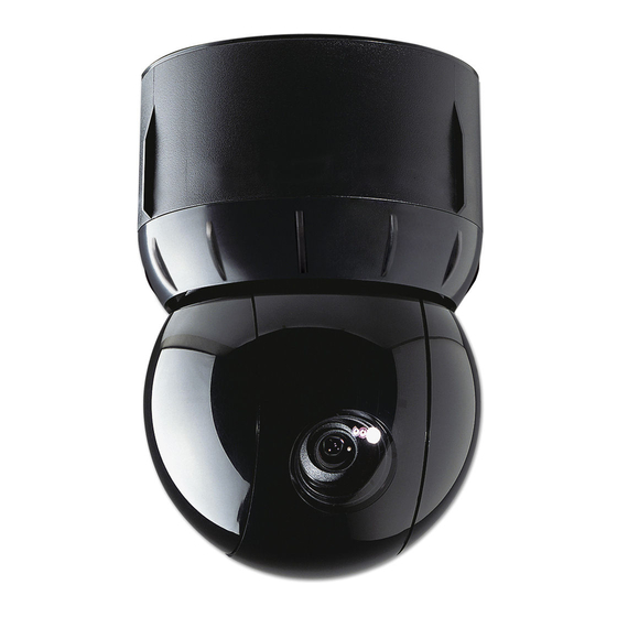
- Page 6 IS SpeedDome’“? WHAT The SensorVision SpeedDome dome designed for retail stores, casinos, manufacturing ties, hotels, hospitals, and a wide variety of other facilities, especially where appearance The SpeedDome is part of a SensorVision CCTV (Closed Circuit Television) system, a network of remote camera dome pans, tilts, zooms, and focuses on the subject, whether it is in low light, moving, or at a distance.
- Page 7 Monochrome Dome uses monochrome cameras 50Hz versions. Color cameras come in l/2” CCD, NTSC, 60Hz and l/2” CCD, PAL, 50Hz versions. The color camera is fully digital, which has several advantages over analog versions. light sensitivity (2.2 lux) and picture resolution (430 TV lines) due to Digital Signal Processing (DSP).
- Page 8 Introduction SENSORVISION SpeedDome...
- Page 9 Automatic SpeedDome going through ignores commands). Automatic this feature enables the lens iris to adjust to different lighting conditions the console to adjust lighting manually. See ‘Iris Preference in this section. Automatic/Manual automatically instructions using keyboard dome can communicate. Automatic synchronizes own internally external frequency...
- Page 10 Pattern Speed Multiplier. operator can multiply the base pattern speed range of the camera (3 -24” per second depending two (6-48”) three (g-72”) or four times (12-96”). host systems have fully proportional (0-50”lsec). Transient Protection. All dome inputs and outputs are opto-coupled, transformer isolated, or provided...
- Page 11 1.3, Installation Indoor and outdoor ure l-2). Indoor available that fits standard For sheet rock, wood, or ceilings with special finishes, ceiling housing hances the appearance For indoor ceilings of 6m or more, a 38mm pipe is added hard ceiling housing are matte white, but can be painted to match decor.
-
Page 12: Installation And Service Features
Figure l-2. SpeedDome housings-mounting Indoor SpeedDome Mountings Pendant RHIPM Hard Ceiling Mount RHICM * Note: There is also a corner mount adapter (RH170) that can be added to RHOWM to mount on the corner of a building wall. Installation In alphabetical order: Interchangeability. -
Page 13: Specifications
Snap-Hinge pins enable the light weight camera chassis to swing out of its housing for servicing or to be removed entirely. V-Lock cumbersome adjustment line by one person at the control console. SPECIFICATIONS See the following pages. SpeedDome SENSORVISION Chassis. Two sets of spring-loaded Adjustment. - Page 14 Indoor SpeedDome Specifications Monochrome (RAS585)lColor U.S. Customary measurements in italics are rounded Operational Pan/Tilt Speed: .__._ - .._._.~.~ .. 3” to 24” per second (based Pan Speed Multiplier:..-.-.- .. 2X, 3X, 4X PanTravel: .._.~.~.~...~.~. 360” Tilt Travel: -._..._._._._...-.-.-. >90”...
- Page 15 Monochrome (RAS585) / Color (RAS586), continued Camera Monochrome/Color Type: Interline transfer CCD array Scanning Area: (H) x 4.8 (V) mm 2: 1 interlace Scanning System: ____ 1 .OVp-p/75Q Video Out: Signal-to-Noise: 48dB (typical) Monochrome only Horizontal Resolution: 500 lines at center Minimum Illumination: 0.225 Iux at fl.2 (AGC on)
- Page 16 Outdoor SpeedDome Monochrome (RAS285)lColor U.S. Customary measurements in italics are rounded Operational Pan/Tilt Speed: 2” to 18” per second for 12-120mm 3” to 24” per second for 8-180mm (based Pan Speed Multiplier: 2x, 3x, 4x PanTravel: 360” Tilt Travel: SO” Pan/Tilt Accuracy: ____ lt.5”...
- Page 17 Monochrome (RAS285) / Color (RAS286), continued Camera Monochrome/Color Type: . Interline transfer 1.27cm (l/2”) CCD array Scanning Area: -- 6.4 (H) x 4.8 (V) mm Scanning System: ____ 2:l interlace Video Out: 1 .OVp-p/75R Signal-to-Noise: 48dB (typical) Monochrome only Horizontal Resolution: 500 lines at center Minimum...
-
Page 18: Before You Begin
BEFORE YOU BEGIN Verifying and Unpacking 2.1.1 Verify that all equipment Verify that the unit shipped is the correct configuration the site. Be organized. Unpack components in a back room. At the installation area, lay out parts in the order you will need them. -
Page 19: Safety Precautions
SAFETY Observe precautions ALWAYS Proper and type of installation. Proper of installation. Safety BE SURE: Electrical product during installation or to any object that you might contact during installation. iNDOOR METHODS This sub-section through Q-9 and Q-18 through Q-20. OUTDOOR METHODS This sub-section through Q-20. -
Page 20: Ceiling Mount
- Indoor Hard Method II - Installation Reauired Parts Hard bount 0351-0393-01 (part of 0200-0178-01, which ships with RHICM). Description Qty. Part “S” hook, open 2897-0004 Chain, Navy link 2898-0002 2882-0112 Eye bolt, IO-24 w/nut 2848-8100-l Washer, flat, SS #lO Nut, locking, 10x24 2838-9154-05 Aluminum tape... - Page 21 __. /ndoor Hard Method 2 - Installation Required Parts RHICM is an ordering vehicle for 01 RHICM, which contains: 0351-0394-01 - (major components listed below) 0200-0178-01 - Indoor Hard Mount; also includes: 0351-0393-01 - Hard Mount Install Kit: Description Qty. “s’...
- Page 22 indoor Hard Mount Place “Z” supports [a] on the ceiling’s top surface. For tile ceilings, make sure the edge of the supports rests flush with edges of tile. Refer to diagram on page Q-4. Place the two “L” supports [b]-cut length, if necessary-over the threaded studs of the “Z”...
- Page 23 Indoor 2x2 We 2x2 Install Components RHl2X2 is an ordering vehicle for 0200-0176-01, contains the following items: 0400-0496-01 - 2x2 SpeedDome Housing 0351-0376-01 - 2x2 Housing Install Kit: Description Qty. Part Bar, ceiling tee 0500-0263-01 S-hook, open 2897-0004 Chain, Navy link 6 FT 2898-0002 0500-0264-04...
- Page 24 indoor 2x2 Tile Mount Set the housing [f] into the ceiling open- ing. For slightly larger openings, see box below. If installing in a 2x2 ceiling, remove an adjacent ceiling tile to aid installation. Clamp the housing to the T-bars by snap- ping a T-bar clip [g] over the raised edge of the housing and the T-bar.
- Page 25 Indoor Pendant Method 1 - Standard Required Parts Pendent Mount Components: RHIPM is an ordering vehicle for dlRHIPM, 0351-0391-01 - Adjustable I-Beam Clamp Kit (not used with this method) 0200-0177-01 - Pendant Housing Assembly; also includes: 0351-0392-01 - Pendant Install Kit, which contains the following items: Description caty.
- Page 26 /n&or pendant Method 2 - I-Beam Required Parts RHIPM is an ordering vehicle for OlRHIPM, 0400-0505-01 - Pendant Housing Assembly; 0351-0392-01 - Pendant Install Kit (not used with this method) 0351-0391-01 - Adjustable I-Beam Clamp Kit: Description Qty. Part Base plate 0500-3975-01 Clamp plate 0500-3976-01...
- Page 27 SpeedDome Required Parts Skirt Assembly - 0400-0507-01 SpeedDome Install Kit - 0351-0377-01: Description Ctty. Part Connector, 211 l-0035-01 BNC jack 211 l-0034-01 Nylon Cable Tie 6009-0006 Procedure Snap the ball [a] of the lanyard hanging from the chassis into the bracket [b] at the top of the housing.
-
Page 28: Chassis Installation
Chassis Installation, Attach the skirt assembly or optional bubble assembly [h] to the chassis by inserting its T-lanyard into a slot [i] on the chassis until both ends catch securely. To lock the chassis in the housing, squeeze ejector pins [j] and swing the chassis all the way up, while easing the cables up through the access holes. - Page 29 Outdoor Over l?oof Mount Required Parts .._.__ ---_._- ..______.I._._..~..~~.~.~...~...~.~.~.~.~.~...~.~.~.~.~.~.~...~.~ Over Roof Install Components 0200-0179-01, SpeedDome Housing Assv - ships with Outdoor SpeedDome 0200-0173-01, Over-Roof Mount Ati 0200-0174-01, Over-Roof Install Hardware Description Plate, mounting Bracket, mounting Base wall/pole mount Over-Roof Install Kit - contains the...
- Page 30 Outdoor Over Roof Mount, continued Place plate [a] in desired loca- tion, level, and mark slots. Plate MUST BE LEVEL. Remove tern- plate, then drill four l/2-inch holes to the required depth for type of wall and hardware used. For each hole into solid concrete, screw two nuts [b] onto an anchor bolt, with two threads of second nut extending over end of bolt to protect threads.
-
Page 31: Outdoor Wall Mount
Outdoor Wall Mount Corner Bracket Required Parts 0200-0179-01 - Outdoor SpeedDome SpeedDome, is required for these installation Wall Mount Option (RHOWM) RHOWM is the orderfna vehicle for 0200-0162-01 which contains the following items: Description Base, wall/pole Support, wall/pole Pipe, 12 in. long Fitting, 90”... - Page 32 Outdoor Wall Mount Feed camera dome cables [h] through mounting bracket (i). Apply sealant [j] to threads of straight pipe [k], then slip pipe over cable and screw pipe into bracket. Slip elbow [I] over cable and screw elbow onto pipe. Once on, elbow opening should face down.
- Page 33 Outdoor Pole Required Parts 0200-0179-01 - Outdoor SpeedDome Housing Assembly, which ships with Outdoor SpeedDome, is required for these installation Pole Mount Components RHOPM is the ordering vehicle for 0200-0161-01, which contains the following items: Description Base, Wall/Pole Support, Wall/Pole Pipe, 12 in.
- Page 34 Outdoor Ceiling Required Parts 0200-0179-01 - Outdoor SpeedDome Housing Assembly, which ships with Outdoor SpeedDome, is required for these installation Ceiling Mount Components RHOCM is an ordering vehicle for 0200-0163-01 which contains the following items: Description Flange Fitting, pipe tee Nipple, short l-l/2x Anchor bolt, 114x2-114, w/hardware Pipe sealant...
- Page 35 Housing Using tamper-proof tool (T-20) remove captive bubble attachment screws [a] from housing, then remove bubble [b]. Next, connect the composite cable compression connector [k] to J2, and the video connector to Jl , on the Outdoor Interface Board [I], mounted on the outside of the bracket.
- Page 36 Housing and Chassis Squeeze the spring-loaded ejector pins [n] together to seat the chassis in the corner receptacles [o]. The RS422 board [p] must face the SpeedDome interface board cables [q] inside the housing. Set the thumbwheel switches [r] to the appropriate address.
- Page 37 Fixed Cameras Parts Required There are three indoor mounting options to place fixed cameras in SpeedDome RD500 - uses an Indoor 2x2 Indoor Housing RD500A - uses an Indoor Pendant Housina RDSOOB - uses an Indoor Hard Mount Description Part 2x2 Indoor Housing 0200-0176-01 Pendant Indoor...
- Page 38 Cable Conversions Replace Cinch-Jones with female compression-type connector (supplied with dome). FEMALE COMPRES- SION-TYF’ECONNECT PN 2109-0254-06 from J-Box Add to a length of bulk composite cable, male and female compression-type connectors male and female BNCs from SpeedDome Cable Conversion Kit, 0351-0403-01. MALE COMPRES- SION-TYPECONNECTOR PN 2109-6271-07...
- Page 39 SpeedDome SENSORVISION...
- Page 40 SpeedDome SENSORVISION...
- Page 41 Overview This appendix describes the interconnection required to operate a Sensormatic Indoor SpeedDome device from an American Dynamics The 2083-02A is part of an American tem that also consists of a CPU and matrix switching Figure 1 illustrates a typical system. Note: This appendix presents...
- Page 42 American 208342A Translator The American American matic SpeedDomes vides two types of inputs and three types of outputs. Note: Up to 16 cameras Translator provided. Inputs Control (Manchester) W, and S on the translator’s 64 domes domes controlled High Speed Data Line-The marked connector the output...
- Page 43 RS-422 Communications The 2083-02A Code Translator consisting of four individual outputs. Up to sixteen cameras may be controlled directly via these outputs Boxes may be connected to these outputs allow the maximum number of outputs to be used. Note: When using Control Code as the data input, each group used must be set as group maximum...
- Page 44 RS-232 Two FE-232 ports are provided and output. control system or the input port of another Alarm Interface devices for cascading connectors. the Table 2 below. Table For the use and addressing devices, Translator. 02A being used is set up for SpeedDome operation While the 2083-02A communications...
- Page 45 Sensormatic RJ860 J-Box The Sensormatic RJ-860 J-Box serves functions depending on the design of the installation: Provides low voltage (24Vac) power for up to ten domes when a central power distribution Acts as a RS-422 1 x 10 bidirectional to increase the available number Units may be cascaded...
- Page 46 Sensormatic RAS585LSlRAS586LS Series The Sensormatic camera device. All connections its Unicafd Data connections designated Drawing the J-Box or another distribution Certain switches designated switch settings only versions is the setting of Sl switch 2. The dome automatically adjusts to the power line frequency Table Switch * Indoor domes.
- Page 47 Appendix A American Dynamics- to=Sensormatic Conversion Charts SpeedDome SENSORVISION...
- Page 48 Table 4. SpeedDome Address A-10 Conversion Chart 1-64 i-64 1-64 l-64 ~~~~ 10s 1-64 l-64 l-64 .54-l I-fsd l-64 l-84 loo-' lO&' loo-' loo-'...
- Page 49 Video .“” 1 loo-198 1Q-l I In-l-lcm 1 loo-198 Appendix A I”“-- 1 193-256 193256 ’ 193-256 193-256 193-256 193-256 193-256 193-256 193-256 193-256 .,,-2.56 1 193-256 193-256 193-256 lP%7Fdi SENSORVISION SpeedDome A-11...
- Page 50 “ . 199-297 298-398 A-12 SENSORVISION S/X?t?d~Omt3 “N _ - . - - _ 257-320 321-384 ,L I -Jo‘+ 321-384 321-384 321-384 321-384 321-384 321-384 321-364 321-384 321-384 321-384 321-384 1 321-364 321-334...
- Page 51 1 397-495 Video Input/ Camera Dome Numbers Address 4&. SENSORVISION Speedfbme ydix A A-13...
- Page 52 1 49 I Aa , ‘w I Aa A-14 SpeedDome SENSORVISION Video...
- Page 53 Appendix A 1 694-792 B NOT USED] 641-704 A-15 SENSORVISION SpeedDome...
- Page 54 Video Input/ Camera 1 694-792 1 793-891 1 79? nnr 1 793-891 70" nn. R?c, A-16 SpeedDome SENSORVISION Video...
- Page 55 Video input/ Camera Dome Numbers Addtess 892-993 892-990 892-990 892490 SENSORVISION SpeedDome Sx A A-17...
- Page 56 Camera/&Box/Switch (0301-0109-01) !=m!s=l 12-pin press-release Connector on J-Box Motherboard green Data HI (T+) white Data out LO (T-) Aux out 1 HI Aux out 1 LO Aux out 2 HI Aux out 2 LO Data in HI (R+) 6 red 5 black Data in LO (R-)
- Page 57 SENSORVSION SpeedDome...
- Page 58 SENSORVISION SpeedDome...
-
Page 59: Design Guidelines
SensorNet Network Understanding the SensorNet network is very important successful installation. This understanding an efficient, reliable, and flexible network that can meet the facility’s long-term needs. This guide provides guidelines for selecting a suitable topology network devices. Distances and device counts contained in this guide assume 22 un-shielded twisted-pair... - Page 60 r SensorNet Network: daisy chain hosts are usually terminated one end; however, this location is not critical. attaches elsewhere, the network becomes star. In this configuration, both end devices :erminated and the host is not terminated. ‘. Backbone Link Guidelines I a backbone network, a single continuous...
-
Page 61: Mounting Procedure
SensorNet G=Position Installation Kit: o351-o739-o1 Description caty. Anchor, toggle and bolt, 114x4 Anchor, wedge, bolt, 114x4 Screw, #10x1 -112 Flat washer, wide, type B, #lO Specifications: Power Source (50-80Hz):..100-l 20/200-240Vac Power Consumption: ....250W max. Voltage Output: . - Page 62 SensorNet G-Position Input Power to J-Box Use the figure below to properly connect AC wires to the TB2 connector for 115Vac or 230Vac operation. IMPORTANT: 230Vac operation jumper changes. Refer to the chassis panel for details. From Chassis to TB2 AC Line to TB2 COLOR PIN FXN...
- Page 63 . SensorNet G-Position Data and Power Indicators The LED indicators allow visual verification of SensorNet signals and power to the dome ports and host/auxiliary ports. Use the status information below to determine proper operation 1 AC PWR is yellow when 24Vac from the transformer to the PCB is present.
- Page 64 SensorNet i=Posifion Installation Kit: ow-o739-o2 Description Qty. Anchor, toggle and bolt, 114x4 Anchor, wedge, bolt, 114x4 Screw, #10x1-1/2 Flat washer, wide, type B, #lO Specifications: Power Source (50-6OHz): ....IOO-120/200-240Vac Power Consumption: .
- Page 65 SensorNet I-Position Input Power to J-Box Use the figure below to properly connect incoming AC wires to the TB2 connector for 115Vac or 230Vac operation. IMPORTANT: 230Vac operation jumper changes. Refer to the chassis panel for details. Chassis to TB2 COLOR Green Black...
- Page 66 SensorNet f-Position Data and Power Indicators The LED indicators allow visual verification SensorNet signals and power to the dome port and host/auxiliary ports. Use the status information below to determine proper operation 1 AC PWR is yellow when 24Vac from the transformer to the PCB is present.
-
Page 67: Parts Required
indoor SpeedDome Parts Required: Description caty. BNC connector BNC jack Nyon cable tie SpeedDomes support either RS422 or SensorNet data interfaces. By setting jumper pins on the dome UniCards, you will be able to easily set the type of data interface required for wiring and cabling. - Page 68 lndoor SpeedDome 5. Set the dial switches [f] on the UniCard to the appropriate dome address. The example below uses address Dial Switches 6. With the dome chassis hanging the data and video cables [g] to P3 and on the UniCard. ‘Y Auxiliary Control...
- Page 69 Outdoor SpeedDome Parts Required: Description ctty. Environmental assy. Bubble assy, outdoor Cap Outdoor Nut hex 1.5 pipe w/ seal RTV compound Pipe sealant BNC connector BNC jack Nyon cable tie SpeedDomes support either RS422 or SensorNet data interfaces. By setting jumper pins on the dome UniCards, you will be able to easily set the type of data interface required for wiring and cabling.
- Page 70 Outdoor SpeedDome, Set jumpers E2 and E3 on the UniCard interface board [k] for RS422 or SensorNet cabling, using Table 3. To locate the jumpers, see the figure on page D-15. The SensorNet interface requires a data line termination at El on the UniCard, depending the dome positions along the cable.
- Page 71 Outdoor SpeedDome, UniCard -Y _--_-_-____ Auxiliary Control outputs Alarm Inputs The UniCard provides an P2 External External Video Sync Input (P2, mate connector 2109-0254-01) to sync the monitors to an external sync generator source. P7 Auxiliary The UniCard also provides 4 TTL Level Alarm Inputs Digital Ground (P5, mate connector...
- Page 72 AMERICAN DYNAMICS Sensormatic CCTV Systems Division One Blue Hill Plaza Pearl River, NY 10965 Technical Support Center (800) 442-2225 Business (914) 624-7600 SENSORMATIC ELECTRONICS CORPORATION 95 1 Yamato Road Boca Raton, FL 3343 l-4425 Technical Support Center (800) 543-9740 Business (561) 989-7000...
Need help?
Do you have a question about the SpeedDome Ultra 8 and is the answer not in the manual?
Questions and answers