
Related Manuals for J&M Nitro Gro 5010


Summary of Contents for J&M Nitro Gro 5010
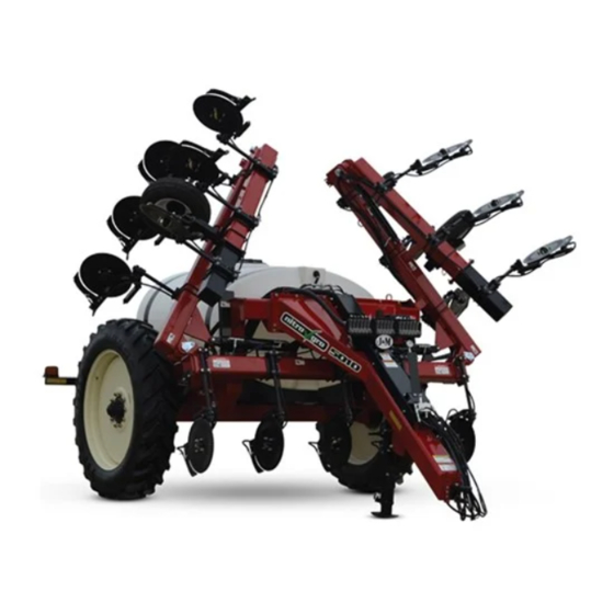
- Page 1 Manual MODEL A S S E M B L Y M A N U A L J&M Manufacturing Co, Inc 284 Railroad Street - P.O. Box 547 | Fort Recovery, OH 45846 | Ph: (419) 375-2376 | Fax: (419) 375-2708 www.jm-inc.com...
- Page 2 Decals...
- Page 3 Decals # Description: Decals Part. No. Grease Decal JM0015104 Warning - Pinch Point JM0014994 Down Pressure Decal JM0035892 Warning - Insert Pin Before Road Transport JM0038103 Danger - Electrocution Hazard JM0035887 Caution - Observe Instructions JM0035881 Danger - Crushing Hazard JM0035883 J&M Oval JM0038110...
- Page 4 Frame 1. Bolt on the back frame with 3/4” x 2-1/2” bolts and 3/4” centerlock hex nuts. 2. Bolt on axle with 1” x 3” bolts and 1” centerlock hex nuts. 3. Set the frame up on blocks. Use a tape measure to ensure the back corner of the applicator frame is approximately 30”...
- Page 5 Frame 7. Connect the yellow hoses to the fittings on the side of the valve bank that are second from the top and drape them down the center of the tongue of the applicator. They will extend to the center of the tongue. Connect the red hoses to the bottom two fittings on the front of the valve bank and extend to the tractor.
- Page 6 Frame 9. Bolt on light bars using 1/2” x 2-1/4” bolts and 1/2” centerlock hex nut. Use the outside holes in the frame when mounting the light bars. 10. Secure rear lights onto the light bars with 1/4” x 3/4” bolts and 1/4” serrated flange nuts. Red lights face out from the applicator are located closer to the inside of the applicator and yellow lights are located closer to the outside.
- Page 7 Frame 13. Use 3/8” x 4” bolts, 2” plastic spacers, and 3/4” serrated flange nuts to fasten down pressure relief valve bank to the front hydraulic hose guard. Connect hose from pressure gauge to down pressure relief valve bank. 14. Run the 1/2” x 300” and 3/8” x 300” hoses from the front of the tongue along the frame of the applicator all the way to the hydraulic pump on the right/passenger side.
- Page 8 Tank 1. Holes are predrilled in the tank for the fittings. Add fittings in the two holes in the back of the tank and the hole in the front. The rubber o-ring on the fitting goes inside the tank and the nut will screw on from the outside.
- Page 9 Tank 3. Place the tank on the saddles by using an overhead hoist. The lid should be positioned to the back of the applicator. 4. Measure the back of the tank from the frame to the seam at the center of the tank. Center the tank so the distance measures about 25”...
- Page 10 Tank 5. Fasten the tank to the saddles using the tank straps. The three tank straps use (4) 1/2” x 5-1/2” bolts and centerlock nuts per strap. 6. Zip tie each circut of hoses together. Attach hydraulic hose holder to frame. Hook all hydraulic hoses through the hydraulic hose holder.
- Page 11 Tank 7. Attach jack mounting bracket to the mounting plate which is welded on the underside of the frame using a 1” x 6” bolt and 1” centerlock hex nut. 8. Using a fork lift or overhead hoist, lift the front end of the applicator off the ground enough to align the four holes on the jack with the four holes on the mounting bracket.
- Page 12 Tank 11. Connect hydraulic hoses to the small pump. The top hose is a 3/8” hose. The bottom hose is a 1/2” hose and will be marked in yellow. The 1/2” hose should go in check vavle with an arrow pointing out from the pump. 12.
- Page 13 Tank 14. Attach flow control mount using (4) 3/8” x 1” serrated flange and serrated flange nut. 15. Connect the 1-1/2” pressure hose to the Raven control valve with M200150BRB90 and tighten clamp. Connect wire harness that comes with Raven control. 16.
- Page 14 Tank 18. Mount the ball valve to the mount plate to rear driver’s side of applicator using 1/2” x 1-3/4” hex bolts and 1/2” serrated flange hex nuts. A wire hangs on the cap of the valve. Before fastening the bolts with the nuts, loop one eyelet of the wires over the inside of the bolt and slide a washer in behind it (as shown below).
- Page 15 Handwash Tank 20. Attach water tank. Use plastic thread dope for spout attachment and plugs. 21. Attach hose from top front of tank to banjo relief valve on Raven control and tighten clamp.
- Page 16 Toolbar 1. Set up main toolbar with the front section level and the back section elevated slightly. 2. Mount down pressure cylinder linkage plates and center down pressure cylinder to the front section with pins. 3. Mount the 4” x 24” wing cylinders. Use a block to support the cylinders. When mounting the cylinders, ensure the bolt on the ram side of the cylinder is facing up and the hydraulic fittings face towards the rear of the toolbar.
- Page 17 Toolbar 4. Die grind the paint off the inside of the holes on the toolbar and the wing extensions that will have pins inserted into them (as shown below). Die grinding makes inserting the pins easier. 5. Mount wing extensions. Start on the right side of the toolbar. Using a lift, align the holes of the wing extension with the holes in the toolbar.
- Page 18 This page intentionally left blank.
- Page 19 Coulter Placement 1. This section of the manual details the coulter mounting process. These instructions can be used for both the initial setup of your applicator and instructions to change the row spacing on your applicator. To change your row spacing, loosen the coulters and follow the directions for that respective row spacing: •“Coulter Mounting - 45cm Row Spacing”...
- Page 20 Coulter Mounting - 45cm Row Spacing Front view Offset coulter 23 coulters mounts are Start coulter 1 shown in red. 45cm row spacing in the middle of the main toolbar 1. Fasten the first coulter in the center of the main toolbar. Measure 45cm on each side to place the next coulter and repeat for all 23 coulters.
- Page 21 Coulter Mounting - 45cm Row Spacing 7. Bottom parts for coulters will be added in later steps. 8. Mount coulter 2 from the opposite direction as coulter 1. Coulter 2 uses the wider channel bracket plate to get around the weldments (shown below). Use (2) 5/8”-11 x 7-1/8” x 8-11/16” square U-bolts to mount the wider channel bracket plate, and (4) 5/8”...
- Page 22 Coulter Mounting - 50cm Row Spacing Front view Offset coulter Start coulter 1 23 coulters mounts are in the middle shown in red. 50cm row spacing of the main toolbar 1. Fasten the first coulter in the center of the main toolbar. Measure 50cm on each side to place the next coulter and repeat for all 23 coulters.
- Page 23 Coulter Mounting - 50cm Row Spacing 7. Bottom parts for coulters will be added in later steps. 8. The U-bolts for coulter 2 go through the slots in the weldment shown below. Continue to measure 50cm across the tool bar to place coulters. Coulter 4 does not use a channel bracket plate. Instead, use (4) 5/8” x 3-1/2”...
- Page 24 Coulter Mounting - 70cm Row Spacing Offset coulter Front view Start coulter 1 mounts are in the middle 15 coulters shown in red. of the main 70cm row spacing toolbar 1. Fasten the first coulter in the center of the main toolbar. Measure 70cm on each side to place the next coulter and repeat for all 15 coulters.
- Page 25 Coulter Mounting - 70cm Row Spacing 7. Bottom parts for coulters will be added in later steps. 8. Continue to measure 70cm across the tool bar to place coulters. 9. Offset coulter mounts are used in areas or hinges that dont allow a direct mount. Coulter 7 uses an offset coulter mount.
- Page 26 Connecting Frame and Coulters to Toolbar 1. Hook chains on each side of axle through the provided hole. Wrap an 8,000 lb stap around the neck of the tongue. Find the right length to pick it up evenly so the load is balanced. Lift slowly over the toolbar and center into position while lowering slowly.
- Page 27 Connecting Frame and Coulters to Toolbar 5. Mount the 4’ x 8” hydraulic cylinders under the toolbar frame as shown below. Secure the cylinders with 1” x 3-3/8” pins. 6. Connect the hoses from the top two ports of the valve bank on the main frame to the 4” x 8” hydraulic lift cylinders.
- Page 28 Coulter and Wheel Finishing 1. Slide on main coulter body with stop inside. The square headed bolt in the stop sits in the drilled depression (as shown below). Insert a roll pin into the bottom hole of the coulter rod to hold the coulter on the rod. Depression for square head bolt...
- Page 29 Coulter and Wheel Finishing 4. Secure each knife to the knife mount using (3) 1/2” lock washers, a 1/2” flat washer, a 1/2”-13 hex nut, a 1/2”-13 x 1-3/4” hex bolt, and a 1/2”-13 x 1-1/4” hex bolt. The shorter bolt is used towards the top of the knife and is threaded into the mount.
- Page 30 Mounting Hubs, Spindles, and Tires 1. Using a fork lift, carefully position the hub and spindle assembly in line with the axle and slide in the spindle. Take care not to mar the threads on the spindle when lifting. After lining up the hole in the spindle with the hole in the axle, insert the 1”-8 x 7”...
- Page 31 Diaphragm and Fertilizer Hose Placement Start adding 3/4” tee and single diaphragm check valves to each QJ mounting pad on each coulter.
- Page 32 Diaphragm and Fertilizer Hose Placement The green hose shown below will go to the start of boom 1. From the first coulter valve you will need 45, 50, or 70cm length hose to connect each coulter based upon which row spacing you are using. The blue hose will be the start of boom 2, and the yellow hose will be the start of boom 3.
Need help?
Do you have a question about the Nitro Gro 5010 and is the answer not in the manual?
Questions and answers