
Related Manuals for J&M NITRO-GRO 5010


Summary of Contents for J&M NITRO-GRO 5010
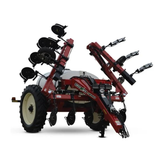
- Page 1 OPERATORS MANUAL 5010 5016 J. & M. Mfg. Co., Inc. 284 Railroad Street - P.O. Box 547 Fort Recovery, OH 45846 Ph: (419) 375-2376 Fax: (419) 375-2708 www.jm-inc.com...
-
Page 2: Table Of Contents
Table of Contents 4-5 ........... . To the Dealer 6 . -
Page 4: To The Dealer
To The Dealer Read manual instructions and safety rules. Make sure all items on the Dealer’s Pre-Delivery and Delivery Check Lists are completed before releasing equipment to the owner. The dealer must complete the Warranty Registration found on the Dealer Portal website located at dealer.jm-inc.com and return it to J. - Page 5 Serial Number Serial Number Location Serial Number________________ Model Number________________ Standard practice when ordering parts or obtaining information from your dealer requires the serial number and model number. Have numbers available before making contact. Dealer Set-Up • Adjust wheels to desired width. •...
-
Page 6: General Information
General Information TO THE OWNER: The purpose of this manual is to assist you in operating and maintaining your nitrogen applicator in a safe manner. Read it carefully. It furnishes information and instructions that will help you achieve years of dependable performance and help maintain safe operating conditions. -
Page 7: Bolt Torque Chart
Bolt Torque Chart Always tighten hardware to these values unless a different torque or tightening procedure is listed for specific application. Fasteners must always be replaced with the same grade as specified in the manual parts list. Always use the proper tool for tightening hardware. Make sure fastener threads are clean and you start thread engagement properly. -
Page 8: Specifications
Specifications SPECIFICATIONS 5000 Series Applicators Tank Size 1,000 Gallon 1,600 Gallon Base Width 30’-0” 40’-0” Ground Clearance 34” 34” Row Spacing* 20”, 30” 20”, 30” Number of Coulters 11, 13, 15, 17, 23, 25 11, 13, 15, 17, 23, 25 Coulter Style Grove Engineered Products (GEP) Grove Engineered Products (GEP) -
Page 9: Safety Rules
Safety Rules ATTENTION! BECOME ALERT! YOUR SAFETY IS INVOLVED! Safety is a primary concern in the design and manufacture of our products. Unfortunately, our efforts to provide safe equipment can be erased by an operator’s single careless act. In addition, hazard control and accident prevention are dependent upon the awareness, concern, judgment, and proper training of personnel involved in the operation, trans- port, maintenance and storage of equipment. -
Page 10: Components
NitroGro Components Holding Tank Light Bar Flow Monitors (Optional) Hitch Toolbar Down Pressure Gauge Down Pressure Relief Valve Gauge Wheel Coulter 3-Section Boom Flow Meter Butterfly Valve Spike Valve Shut Off Agitation Valve Strainer Hydraulic Pump Rinse Tank Tank Fill Valve 2”... - Page 11 Flow Monitors Optional Flow Monitors are available to allow the operator to see the rate of flow to each coulter through a floating ball located inside the transparent inspection tube. Each coulter is connected with a separate supply hose. Down Pressure Relief Valve The Down Pressure Relief Valve provides adjustable hydraulic pressure to force the coulters on the wings into the ground while allowing the wing to flex up...
- Page 12 Coulter The number of coulters is determined by the number of rows (usually one less or one more). So the number of rows will be even, and the number of coulters will be odd, since you are placing the nitrogen between the rows. Example, a 16 row unit will have either 15 or 17 coulters.
- Page 13 Transport Latches The Transport Latches are designed for safe transport. When the Transport Latches are resting on the Main Frame and the pins are installed, the Nitro Gro Applicator can not lower. Shut-Off & Fill Valve The Nitro-Gro Applicator is standard equipped with a 2” Shut-Off and Fill Valve.
- Page 14 Agitation Valve (Hydraulic Pump Units Only) The Agitation Valve is designed to allow air to escape from the pump so it can easily prime. When you’re running in the field, a little liquid runs through the Agitation valve back to the tank. (You will need to adjust the amount of agitation.) The Agitation Valve can also be used...
-
Page 15: Pre-Operation Checklist
Pre-Operation Checklist PREPARING THE NITRO-GRO APPLICATOR: IMPORTANT - Before putting the applicator into operation, check the machine for damaged or worn parts and replace as necessary. Only use a tractor with sufficient power and weight to operate the applicator.( For 16 Row 170 HP, 12 Row 130HP) Be sure the applicator is properly attached to the tractor, the pin is properly secured, and (if equipped) the safety chain(s) are properly installed. - Page 16 Hitching and Unhitching the Applicator Connect the applicator to the tow vehicle using a hitch pin and make sure a retaining pin is secured in the hitch pin. Always attach the safety chains to the applicator and the tow vehicle. WARNING –...
- Page 17 Fertilizer Pump Your Nitro-Gro Applicator is equipped with the Ace FMC-150-HYD-206 pump. Note: Refer to the pump’s owners manual to regulate the hydraulic flow to the pump. Attach the pump hydraulic hoses to the tractor so the pump operates in the lower/retract position. The pump can then be turned off in the forward ”float”...
-
Page 18: Wheel Spacing
Adjusting the Field Depth • The center section of coulters should be set first. The Toolbar Cylinders have spacers included. Add or remove spacers until the center section is positioned at the appropriate depth. Lower the unit until the lift cylinders bottom out on the stroke control spacers. - Page 19 Operation 1) Hook tractor to Nitro-Gro and adjust hitch so that frame on applicator is level or tilting back slightly. 2) Hook up hydraulic lines. Set #1 - Green Hoses - Raise & Lower/ Wing Kick/ Down-pressure Set#2 - Red Hoses - Wing Fold Set#3 - Black Hoses - Hydraulic Pump IMPORTANT - For the black hoses hook the return hose to a low pressure return port at the tractor.
-
Page 20: Quick Start
Quick Start For The Raven 440 Controller With Phoenix 10 GPS Initial Console Programming HINT: If you enter the wrong value when entering your data press “ENTER” then press “ENTER” again and re-enter your value again. • Select the unit of measure by pressing the CE button until the desired until of measure appears in the display and press “ENTER” NOTE - The unit of measure for the United States is Volume per Acre. -
Page 21: Break In Period
Break In Period First 30 minutes of operation: 1. Check that all coulters and nozzles are clean and working properly. Clean and adjust accordingly. 2. Check all hydraulic and chemical lines. Be sure none of them are kinked, pinched or leaking. Adjust lines accordingly. 3. -
Page 22: Troubleshooting
Troubleshooting WARNING - MAKE SURE THAT ALL POWER IS SHUT OFF BEFORE SERVICING THE APPLICATOR. MAINTENANCE AND REPAIR SERVICE WORK TO BE PERFORMED BY QUALIFIED SERVICEMEN ONLY. Trouble... Possible Cause... Possible Remedy... • Use fold/unfold remote • Actuating raise/lower remote Wings only partially unfold instead of fold/unfold remote •... -
Page 23: Storage
Service To prolong the life of your Nitro-Gro applicator, perform the following on a regular basis: 1. Grease coulter hubs, 2 pumps every 50 hours. 2. Check lighting before over the road transport. Make sure lights and SMV emblem are clean from dirt and field debris. 3. -
Page 24: Safety Signs
Safety Signs ATTENTION! BECOME ALERT! YOUR SAFETY IS INVOLVED! Replace Immediately If Damaged or Missing Description: Decals Part. No. Grease Decal JM0015104 Warning - Pinch Point JM0014994 Down Pressure Decal JM0035892 Warning - Insert Pin Before Road Transport JM0038103 Danger - Electrocution Hazard JM0035887 Caution - Observe Instructions JM0035881... - Page 25 Safety Signs...
- Page 26 5000 Flow Monitor Description Part. No. 20511-00 O-Ring x .38in Hose Barb 90 Deg JM0024469 3/8 Hose Clamp (Not Shown) JM0039206 20513-00 O-Ring x .75in Hose Barb 90 Deg JM0024468 3/4 Hose Clamp (Not Shown) JM0039205 20460-00 Flow Indicator JM0021569 1/4”-20 Gr5 Z Centerlock Hex Nut JM0001505 1/4”-20 x 2”...
- Page 27 5000 Pressure Gauge & Shroud Description Part. No. 1/2" Hose Holder JM0027120 3/8"-16 x 4" Gr5 Z Hex Bolt JM0002098 3/8”-16 x 1” Gr5 Z SF Hex Bolt JM0002092 3/8"-16 Gr5 Z Centerlock Hex Nut JM0001512 3/4 DIA x .385 x 2.0 JM0002444 Hose Shroud - Tongue JM0034836...
- Page 28 5000 Fill Valve 2” & 3” Description (3” Quick Fill) Part. No. Description (2” Quick Fill) Part. No. 1/2"-13 Gr5 Z Centerlock Hex Nut JM0001511 1/2"-13 Gr5 Z Centerlock Hex Nut JM0001511 Ball Valve Mount Plate 3" Banjo JM0034894 Ball Valve Mount Plate 2"FP Banjo JM0034889 1/2-20 x 1 Gr5 Z Hex Bolt JM0028442...
- Page 29 5000 Strainer & Hydraulic Pump Description Part. No. 2" Manifold Flange x 90 deg 1-1/2" Hose Barb JM0034352 2" Manifold Tee x 1" Manifold JM0035116 Ball Valve - 1" Manifold Flange JM0033824 1" Flange x 3/4" Hose Barb JM0021401 3/4” Hose Clamp(Not Shown) JM0039205 90 Deg Coupling - 2"...
- Page 30 5000 Check Valve Description Part. No. Diaphragm Check Valve 3/8" Hose Single JM0036383 Diaphragm Check Valve 3/4” Hose Tee JM0036379 Diaphragm Check Valve 3/4” Hose Single JM0036381 1a 3/8” Hose Clamp (Not Shown) JM0039206 1b 3/4” Hose Clamp (For the 3/4” Diaphragm Check Valve) JM0039205 Orifice (Not used with injectors) Specify pg 55 Seat Gasket...
- Page 31 5000 Ground Drive Pump Description Part. No. Roller Chain #50 JM0034463 50A45 Sprocket #50 Roller Chain JM0034459 Sprocket Mount "Ground Drive Pump" JM0034442 14 x 6 Wheel 1 1/8 Inset JM0019535 ST215-75D14 Tire Carlisle Sport Trail JM0019529 Ground Drive Pump Pivot JM0036063 3/8"-16 x 1"...
- Page 32 5000 GEP Coulter Blade & Depth Control Assembly Spool Assembly Description Part. No. Description Part. No. Dust Cap JM0038288 Dust Cap Keeper JM0038391 1/8” Cotter Pin JM0004177 1/2”-13 Gr5 Z Hex Nut JM0002124 1/2” castle nut JM0038277 1/2” Zinc Finish Lock Washer JM0019021 Hub Washer JM0038278...
- Page 33 5000 GEP Coulter Coulter Assembly Knife Assembly Description Part. No. 1/2” -13 x 1-1/4” Gr5 Z Hex Bolt JM0001513 1/2” Zinc Finish Lock Washer JM0019021 Wiese Knife JM0031273 Shims- 1/8” JM0038415 Knife Bracket JM0038279 Coulter Arm JM0038397 1/2” USS Flat Washer JM0003082 1/2”-13 Gr5 Z Hex Nut JM0002124...
- Page 34 5000 Hitch Description Part. No. 3/4”-10 x 6” Gr8 Z Hex Bolt JM0037185 3/4”-10 Gr5 Z Centerlock Hex Nut JM0002147 CTD Perfect Hitch Base PP23XLR JM0037174 CTD Perfect Hitch Clevis 1-1/4” x 1-3/4” Slot JM0037173 Hitch Assembly (Items 1 through 4) JM0037177 Safety Chain (SC-525875) JM0027440...
- Page 35 Wings Description Part. No. 1” x 3.4 Clevis Pin JM0001816 Cotter Pin JM0003064 3/4”-10 x 3” Gr5 Z Hex Bolt JM0027464 Pivot Pin - 2-1/2” Dia With Bolt Retainer JM0031502 3/4”-10 Gr5 Z Centerlock Hex Nut JM0002147 3/8”-16 x 1/2” Socket Set Screw Nylon Tip JM0037255 Shaft - Down pressure Cylinder JM0032428...
- Page 36 Wings Description Part. No. Pin - 1” x 6 LG JM0031495 Hose Mount JM0036703 1” USS Flat Washer JM0003063 Pin - 1” x 5” LG JM0031496 1” x 3-1/2” Clevis Pin with Cotter Pins JM0001817 Sleeve Composite Bearing JM0020546 3” x 14” Welded Cylinder JM0035057 Linkage - Outside Wing JM0030333...
- Page 37 5000 Wing Wheel Description Part. No. Square U-Bolt 7-1/8” Inside Width x 9” Length, 5/8”-11 JM0020901 Gauge Wheel Mount JM0031518 Gauge Wheel Assembly (Right Hand) JM0031511 Gauge Wheel Assembly (Left Hand) JM0031520 5/8”-11 Gr5 Z Centerlock Hex Nut JM0002146 5/8” x 7” Hitch Pin JM0003079 3/16”...
- Page 38 Spindle Description Part. No. 480/80R42 Tire Firestone JM0020038 380/90R46 Tire Firestone JM0016170 Wheel, 46 x 12 10 Holes JM0029935 Wheel, 42 x 16 10 Holes JM0020015 1/4”-20 x 3/4” Gr5 Z Hex Bolt JM0001507 Dust Cap (909921) JM0018954 3/8” x 2-3/4” Z Roll Pin (905945) JM0018956 2”-12 Gr5 Z Slotted Spindle Nut (912973) JM0015899...
- Page 39 Tool Bar Description Part. No. 3/4”-10 x 3” Gr5 Z Hex Bolt JM0027464 3/4”-10 Gr5 Z Centerlock Hex Nut JM0002147 1” x 3-1/2” Clevis Pin with Cotter Pins JM0001817 4” Bore x 8” Stroke Welded Cylinder JM0030757 Toolbar Base Section (2016, 2017) JM0034136 Toolbar Base Section (After 2017) JM0039525...
- Page 40 Frame Frame 2016 & 2017 Part. No. Frame After 2017 Part. No. Rear Frame 5016 JM0033742 Rear Frame 5016 JM0039435 Rear Frame 5010 JM0033744 Rear Frame 5010 JM0033744 3/4”-10 Gr5 Z Centerlock Hex Nut JM0002147 3/4”-10 Gr5 Z Centerlock Hex Nut JM0002147 3/4”-10 x 3”...
- Page 41 Wire Harness Light Harness Part. No. Main Wiring Harness with 7 Prong Connector JM0027077 Soil Conditioner Light Wiring Harness JM0027080 Light Enhancer and Adapter Kit (3 wires) JM0010566...
- Page 42 SCS 450 Liquid Control System Description Part No. Raven SCS450 Control Console JM0039335 Raven Console Cable (10’) SCS 440/450 JM0039337 Remote Switch Cable for Implement Engagement - Raven 450 Control JM0050676 Mini Wisker Limit Switch JM0050161 Phoenix GPS Speed Sensor JM0039338 Raven Flow Cable - 6 Boom (12’) - 3 Pin Weather Pack JM0039336...
- Page 43 ISO Liquid Control System Description Part No. Raven Cable ISOBUS Hitch to Raven ECU (12’) JM0039341 Raven Cable ISOBUS Hitch to Raven ECU (17’) JM0051018 Remote Switch Cable for Implement Engagement - ISO Control JM0050677 Mini Wisker Limit Switch JM0050161 Raven ISO Single Product Kit JM0039339 Raven Flow Cable - 6 Boom (12’) - 3 Pin Weather Pack...
-
Page 44: Fertilizer Hose Routing
Fertilizer Hose Routing - Ground Drive Pump without Flow Monitors Tank Fill Valve 2” or 3” Ground Drive Manifold Ground Drive Pump Strainer Tank Valve Quick Jet Check Valve Description Part. No. 19’ x 1-1/2” Hose from Pump to Manifold (1600 Gal.) JM0040211 15’... - Page 45 Fertilizer Hose Routing - Ground Drive Pump with Flow Monitors Tank Fill Valve 2” or 3” Ground Drive Manifold Ground Drive Pump Flow Monitors Strainer Tank Valve Quick Jet Check Valve 7 From 8 From 4 From 3 From Center Center Center Center...
- Page 46 Fertilizer Hose Routing - Hydraulic Pump without Flow Monitors Tank Fill Valve 2” or 3” Hydraulic Pump Manifold Agitation Valve Strainer Hydraulic Driven Pump Quick Jet Check Valve Description Part. No. 1-1/2” x 228”; Hose from Hydraulic Pump to Manifold (1600 Gal.) JM0040211 1-1/2”...
- Page 47 Fertilizer Hose Routing - Hydraulic Pump with Flow Monitors Tank Fill Valve 2” or 3” Hydraulic Pump Manifold Agitation Valve Strainer Hydraulic Driven Pump Flow Monitors Quick Jet Check Value 7 From 8 From 4 From 3 From Center Center Center Center Center...
-
Page 48: Hydraulics Schematic
Hydraulics Schematic 3”x14” 3”x14” Fold/Unfold Fold/Unfold 4”x24” Fold/Unfold 4”x24” Fold/Unfold 4”x8” Down Pressure 4”x8” 4”x8” Raise/Lower Raise/Lower 0-1500 PSI Pressure Gauge Hydraulic Pump Manifold 23 24... - Page 49 Hydraulics Schematic Description Part. No. 3/8" Male JIC x 1/2" Male ORB; 90 Degree Elbow JM0037159 3" x 14" Welded Non-Cushion JD Cylinder JM0035057 Seal Kit for 3" x 14" Hydraulic Cylinder (30014-138) (JD-607) JM0039240 3/8" x 104" Hydraulic Hose 104inch6M3K-6G-6FJX-6G-6FJX JM0041615 3/8"...
- Page 50 Injectors - 20” Row Spacing 20 Gallons Per Acre 25 Gallons Per Acre Speed (MPH) #10 Injector (psi) #15 Injector (psi) #20 Injector (psi) #30 Injector (psi) #40 Injector (psi) GPM (per nozzle) 0.34 0.43 0.52 0.60 0.69 0.77 0.86 0.95 1.03 0.43 0.54 0.64 0.75 0.86 0.97 1.07 1.18 1.29 Flow Indicator 1/2"...
- Page 51 Injectors - 20” Row Spacing 50 Gallons Per Acre 55 Gallons Per Acre Speed (MPH) #10 Injector (psi) 103 115 104 115 129 #15 Injector (psi) #20 Injector (psi) #30 Injector (psi) #40 Injector (psi) GPM (per nozzle) 0.86 1.07 1.29 1.50 1.72 1.93 2.15 2.36 2.58 0.95 1.18 1.42 1.66 1.89 2.13 2.36 2.60 2.84 Flow Indicator 1/2"...
- Page 52 Injectors - 22” Row Spacing 15 Gallons Per Acre Speed (MPH) Description Part. No. #10 Injector (psi) #10 NitroGro Injector JM0036459 #15 Injector (psi) #15 NitroGro Injector JM0036460 #20 Injector (psi) #20 NitroGro Injector JM0036462 #30 Injector (psi) #30 NitroGro Injector JM0036463 #40 Injector (psi) #40 NitroGro Injector...
- Page 53 Injectors - 22” Row Spacing 40 Gallons Per Acre 45 Gallons Per Acre Speed (MPH) #10 Injector (psi) 102 114 #15 Injector (psi) #20 Injector (psi) #30 Injector (psi) #40 Injector (psi) GPM (per nozzle) 0.76 0.95 1.14 1.32 1.51 1.70 1.89 2.08 2.27 0.85 1.06 1.28 1.49 1.70 1.92 2.13 2.34 2.55 Flow Indicator 1/2"...
- Page 54 Injectors - 30” Row Spacing 15 Gallons Per Acre Speed (MPH) #10 Injector (psi) Description Part. No. #15 Injector (psi) #10 NitroGro Injector JM0036459 #20 Injector (psi) #15 NitroGro Injector JM0036460 #30 Injector (psi) #20 NitroGro Injector JM0036462 #40 Injector (psi) #30 NitroGro Injector JM0036463 GPM (per nozzle)
- Page 55 Injectors - 30” Row Spacing 40 Gallons Per Acre 45 Gallons Per Acre Speed (MPH) #10 Injector (psi) 115 128 143 113 132 146 163 #15 Injector (psi) #20 Injector (psi) #30 Injector (psi) #40 Injector (psi) GPM (per nozzle) 1.03 1.29 1.55 1.81 2.06 2.32 2.58 2.84 3.10 1.16 1.45 1.74 2.03 2.32 2.61 2.90 3.19 3.48 Flow Indicator 1/2"...
- Page 56 Knife - 20” Row Spacing 10 Gallons Per Acre 15 Gallons Per Acre Speed (MPH) 0.075 Orifice Pressure (psi) 0.107 Orifice Pressure (psi) 0.132 Orifice Pressure (psi) 0.161 Orifice Pressure (psi) GPM (per nozzle) 0.15 0.19 0.23 0.27 0.30 0.34 0.38 0.42 0.46 0.23 0.29 0.34 0.40 0.46 0.51 0.57 0.63 0.68 Flow Indicator Red Glass Level 0.3 Flow Indicator 1/2"...
- Page 57 Knife - 20” Row Spacing 40 Gallons Per Acre 45 Gallons Per Acre Speed (MPH) 0.075 Orifice Pressure (psi) 103 117 131 145 103 119 134 150 165 0.107 Orifice Pressure (psi) 0.132 Orifice Pressure (psi) 0.161 Orifice Pressure (psi) GPM (per nozzle) 0.61 0.76 0.91 1.07 1.22 1.37 1.52 1.67 1.83 0.68 0.86 1.03 1.20 1.37 1.54 1.71 1.88 2.05 Flow Indicator 1/2"...
- Page 58 Knife - 22” Row Spacing 10 Gallons Per Acre 15 Gallons Per Acre Speed (MPH) 0.075 Orifice Pressure (psi) 0.107 Orifice Pressure (psi) 0.132 Orifice Pressure (psi) 0.161 Orifice Pressure (psi) GPM (per nozzle) 0.17 0.21 0.25 0.29 0.33 0.38 0.42 0.46 0.50 0.25 0.31 0.38 0.44 0.50 0.57 0.63 0.69 0.75 Flow Indicator Red Glass Level Flow Indicator 1/2"...
- Page 59 Knife - 22” Row Spacing 40 Gallons Per Acre 45 Gallons Per Acre Speed (MPH) 0.075 Orifice Pressure (psi) 100 116 131 146 161 116 133 150 167 184 0.107 Orifice Pressure (psi) 0.132 Orifice Pressure (psi) 0.161 Orifice Pressure (psi) GPM (per nozzle) 0.67 0.84 1.00 1.17 1.34 1.51 1.67 1.84 2.01 0.75 0.94 1.13 1.32 1.51 1.70 1.88 2.07 2.26 Flow Indicator 1/2"...
- Page 60 Knife - 30” Row Spacing 10 Gallons Per Acre 15 Gallons Per Acre Speed (MPH) 0.075 Orifice Pressure (psi) 0.107 Orifice Pressure (psi) 0.132 Orifice Pressure (psi) 0.161 Orifice Pressure (psi) GPM (per nozzle) 0.23 0.29 0.34 0.40 0.46 0.51 0.57 0.63 0.68 0.34 0.43 0.51 0.60 0.68 0.77 0.86 0.94 1.03 Flow Indicator Red Glass Level 0.9 Flow Indicator 1/2"...
- Page 61 Knife - 30” Row Spacing 40 Gallons Per Acre 45 Gallons Per Acre Speed (MPH) 0.075 Orifice Pressure (psi) 103 124 145 165 186 207 228 119 142 165 189 212 235 259 0.107 Orifice Pressure (psi) 102 114 0.132 Orifice Pressure (psi) 0.161 Orifice Pressure (psi) GPM (per nozzle) 0.91 1.14 1.37 1.60 1.83 2.05 2.28 2.51 2.74 1.03 1.28 1.54 1.80 2.05 2.31 2.57 2.83 3.08...
Need help?
Do you have a question about the NITRO-GRO 5010 and is the answer not in the manual?
Questions and answers