Siemens LME7 Series Basic Documentation
Burner control
Hide thumbs
Also See for LME7 Series:
- Technical instructions (140 pages) ,
- Basic documentation (245 pages) ,
- Manual (106 pages)
Table of Contents

Related Manuals for Siemens LME7 Series


Summary of Contents for Siemens LME7 Series
- Page 1 LME7… Burner control Basic Documentation The LME7… and this Basic Documentation are intended for use by OEMs which integrate the LME7... in their products. Software version 01.01 Building Technologies HVAC Products CC1P7105en 13.10.2009...
- Page 2 Supplementary documentation Product Range Overview LME… ................Q7101 2/164 Building Technologies Basic Documentation LME7… CC1P7105en HVAC Products Safety notes 13.10.2009...
- Page 3 Contents Safety notes......................9 Warning notes .......................9 Mounting notes....................10 Installation notes ....................11 Electrical connection of flame detectors............12 Commissioning notes ..................13 Standards and certificates................. 14 Life cycle......................14 Disposal notes....................14 System makeup / function description.............. 15 Features......................16 Type summary....................
- Page 4 Resetting the burner control................28 Limitation of repetitions (can be parameterized) (depending on parameter P240) ....................28 Operation, indication, diagnostics..............29 Operation ......................29 Operational state indication................29 Diagnostics of the cause of fault............... 30 Inputs / Outputs ....................32 PME71.401......................
- Page 5 12.2.2 Gas pilot ignition 1 (Gp1/1), 1-stage..............54 12.3 Connection diagram for LME72.000... with actuator SQM4... (example 1) ......................... 55 12.4 Time table and settings for program sequence PME72.541......56 12.5 LME72.000..: Inputs and outputs / internal connection diagram ....57 12.6 Parameter list PME72.541...
- Page 6 15.2.3 Gas pilot ignition 1 (Gp1/2), 1-stage, with valve proving ........ 69 15.2.4 Gas direct ignition 1 (Gp1/2), 1-stage, with valve proving ......69 15.2.5 Valve proving of gas valves................70 Valve proving with separate pressure switch (P LT) ........70 Valve proving –...
- Page 7 18.6.1 Maximum possible resolution................69 18.6.2 Standardization of modulation range..............69 18.7 Setting the minimum power control step (P123) in modulating mode via analog input signal X65 ................70 Operation via the AZL2….................. 71 19.1 Description of the unit / display and buttons ............ 71 19.2 Meaning of symbols on the display..............
- Page 8 19.9 Operating variants of the parameters ............... 94 19.9.1 Parameters without index, with direct display..........94 19.9.1.1. Example of parameter 225 Gas prepurge time on the parameter level..94 19.9.2 Parameters without index, with no direct display..........96 19.9.2.1. Example of parameter 224 Specified time for air pressure signal on the parameter level....................
- Page 9 The LME7... are safety devices! Do not open, interfere with or modify the unit. Siemens does not assume responsibility for damage resulting from unauthorized interference! • All activities (mounting, installation and service work, etc.) must be performed by qualified staff •...
- Page 10 Mounting notes • Ensure that the relevant national safety regulations are complied with 168,8 Installation notes 73,9 O5 (3x) Program module Operating panel 7113z05e/1009 (73,9) Outer contour housing Figure 1: Mounting – mounting surface Mounting surface 10/164 Building Technologies Basic Documentation LME7... CC1P7105en HVAC Products 1 Safety notes...
- Page 11 Since the BCI has no safe separation from mains voltage, the signal cable AGV50... between LME7… and AZL2…, or LME7… and OCI410…, must conform to certain specifications. Siemens has specified the signal cable AGV50... for use under the burner hood (cable supplied by Hütter; refer to «Technical data»). When using sig- nal cables of other manufacture, Siemens’...
- Page 12 Electrical connection of flame detectors It is important to achieve practically disturbance- and loss-free signal transmission: • Never run the detector cable together with other cables – Line capacitance reduces the magnitude of the flame signal – Use a separate cable •...
- Page 13 Commissioning notes • For display of the flame on the AZL2…, following general conditions apply: - Display is subject to various component tolerances so that deviations of ±10 % can occur - Note that for physical reasons there is no linear relationship between flame display and detector signal values The functions of the following available or required input state signals must be checked: •...
- Page 14 1.6 Standards and certificates Conformity to EEC directives - Electromagnetic compatibility EMC (immunity) 2004/108/EC - Directives for gas-fired appliances 90/396/EEC - Low-voltage directive 2006/95/EC ISO 9001: 2000 ISO 14001: 2004 Cert. 00739 Cert. 38233 Identification code to EN 298 chapter 4 •...
- Page 15 System makeup / function description The LME7... is a microprocessor-based burner control with matching system compo- nents for the control and supervision of forced draft burners of medium to high capacity. LME7… are used for the startup and supervision of 1- or 2-stage gas forced draft burners in intermittent operation.
- Page 16 The LME7... system components (display and operating unit AZL2...) are connected di- rectly via BCI to the LME7... basic unit. All safety-related digital inputs and outputs of the system are monitored by a contact feedback network. For intermittent operation in connection with the LME7..., the ionization probe and optional the UV flame detector QRA2..., QRA4.U or QRA10...
- Page 17 Type summary 3.1 Burner controls Microprocessor-based burner control for single-fuel burner of medium to large capacity, one actuator. Type reference Mains voltage AC 110 V Mains voltage AC 230 V Pressure switch-min-gas / POC Pressure switch valve proving Air pressure switch Ionization probe QRA2...
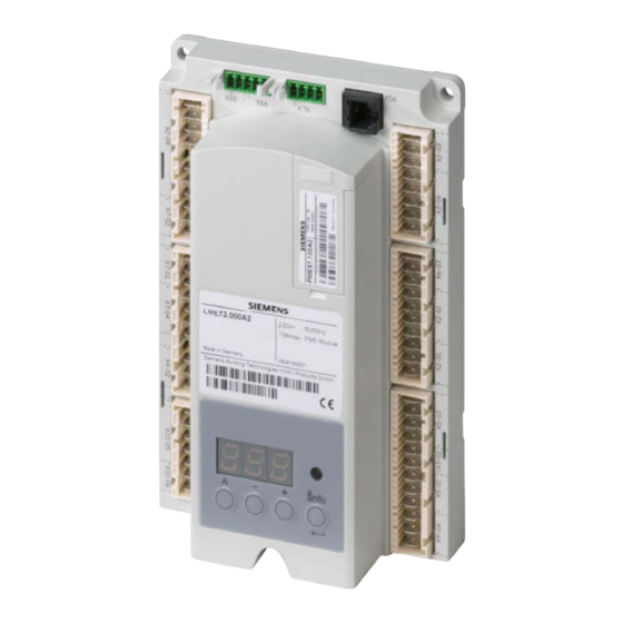
- Page 18 3.2 Program module Example: Type reference Mains voltage AC 110 V Mains voltage AC 230 V For operation with LME71.000A... For operation with LME72.000A... For operation with LME73.000A2 Gas program forced draft burner Gas program atmospheric burner 1-stage / 2-stage or 1-stage modulating Pilot burner intermittent / interrupt Modulating via actuator (pneumatically, mechanical gas air ration control)
- Page 19 Technical Data 4.1 Basic unit LME7... Mains voltage AC 120 V AC 230 V Mains frequency 50 / 60 Hz ±6 % 50 / 60 Hz ±6 % External primary fuse (Si) Max. 6,3 A (slow) Max. 6,3 A (slow) Power consumption <10 W, typical <10 W, typical...
- Page 20 4.3 Terminal rating «Outputs» Total contact loading: • Rated voltage AC 120 V AC 230 V 50 / 60 Hz 50 / 60 Hz • Unit input current X3-04 Max. 5 A Max. 5 A (safety loop) from: - Fan motor contactor - Ignition transformer - Fuel valves Individual contact loading:...
- Page 21 Safety loop (SL) X3-04/2, safety valve (SV) X6-03/3, POC X2-02/3 • Rated voltage AC 120 V AC 230 V 50 / 60 Hz 50 / 60 Hz • Total current • Power factor Cosϕ >0.4 Cosϕ >0.4 4.4 Cable lengths •...
- Page 22 4.7 Signal cable AGV50... 4.7.1 AZL2... → BCI Signal cable Color white Unshielded Conductor 4 x 0.141 mm² With jack RJ11 Cable length - AGV50.100 Supplier (alternative) Recommendation: Hütter http://www.huetter.co.at/telefonkabel.htm Location Under the burner hood (arrangements for SKII EN60730-1 additional required) 4.8 Dummy plug for RJ11 Dummy plug For 6 pin modular plug (RJ11)
- Page 23 4.9 Environmental conditions Storage DIN EN 60721-3-1 Climatic conditions Class 1K3 Mechanical conditions Class 1M2 Temperature range -40...+70 °C Humidity <95 % r.h. Transport DIN EN 60721-3-2 Climatic conditions Class 2K3 Mechanical conditions Class 2M2 Temperature range -40...+70 °C Humidity <95 % r.h.
- Page 24 4.10 Flame supervision with ionization probe No-load voltage at terminal ionization AC 300 V probe (ION) (X10–05, terminal 2) Caution! • The ionization probe must be protected against electric shock haz- ard (electric shock hazard)! • When monitoring ionization currents in earth-free mains, connect terminal X10-05/1 to burner ground Short-circuit current Max.
- Page 25 4.11 Flame supervision with UV flame detector QRA2... / QRA4.U / QRA10... Operation voltage AC 280 V ±15 % 50...60 Hz ±6 % Mains frequency Required detector current Min. 70 µA Possible detector current - Operation Max. 700 µA Perm. length of detector cable - Normal cable, laid separately ¹) Max.
- Page 26 Dimensions Dimension in mm 108,8 LME7... 54,4 7105m02/0407 32,3 9,65 18,5 18,5 29,5 Figure 5: Dimension LME7... 26/164 Building Technologies Basic Documentation LME7... CC1P7105en HVAC Products 5 Dimensions 13.10.2009...
- Page 27 Function 6.1 Preconditions for burner startup • Burner control must be reset • All contacts in the line are closed, request for heat • No undervoltage • Air pressure switch (LP) or POC must be in its no-load position, or Dbr1 is con- nected to X2-02 •...
- Page 28 6.4 Control sequence in the event of fault If lockout occurs, the outputs for the fuel valves, the burner motor and the ignition equip- ment immediately deactivated (<1 second). Cause Response Restart Mains voltage failure Safety shutdown Voltage below undervoltage threshold Restart Voltage above undervoltage threshold Extraneous light before safety time (TSA)
- Page 29 Operation, indication, diagnostics 7.1 Operation Lockout reset button (info button) (EK) is the key operating element for resetting the burner control and for activating / deactivating the diag- nostics functions. Yellow The multicolor signal lamp (LED) is the key indicating element for visual Green diagnostics.
- Page 30 7.3 Diagnostics of the cause of fault After lockout, the red fault signal lamp (LED) will remain steady on. In that condition, vi- sual diagnostics of the cause of fault according to the error code table can be activated by pressing the lockout reset button (info button) for more than 3 seconds. Pressing the lockout reset button (info button) again for at least 3 seconds, interface diagnostics will be activated.
- Page 31 Error code table Red blink code of fault signal lamp (LED) Possible cause 2 x blinks No establishment of flame at the end of the safety time (TSA) - Faulty or soiled fuel valves - Faulty or soiled flame detector - Poor adjustment of burner, no fuel - Faulty ignition equipment 3 x blinks...
- Page 32 Inputs / Outputs Figure 7: Inputs / Outputs 32/164 Building Technologies Basisdokumentation LME7... CC1P7105de HVAC Products 8 Inputs / Outputs 24.09.2009...
- Page 33 PME71.401... 9.1 Program sequence PME71.401... → For connection diagram fuel train «G» Shutdown Startup Operation 2. s tage 1. stage Operating unit parameter number 224 225 226 257 Display AZL2... oP: P2 oP: P1 Display 7 segment in the LME... LED blinking RAST5 plug Relay...
- Page 34 Connection diagrams fuel train applications (examples) 9.2.1 Gas direct ignition (G), 1-stage Program Gas direct 1-stage LME71.000... X7-04 Figure 9: Connection diagram fuel train gas direct ignition (G), 1-stage 9.2.2 Gas direct ignition (G), 2-stage Program Gas direct 2-stage LME71.000... X7-01 X7-04 Figure 10: Connection diagram fuel train gas direct ignition (G), 2-stage...
- Page 35 9.3 Time table and settings for program sequence PME71.401... Type Times in seconds PME71.401... P225 P226 P257 P230 P234 P224 max. min. min. approx. min. min. approx. Requirements Factory setting t3n+0.45 29.106+2.1 2.058 2.205+0.3 8.232 13.818 Max. 1237+2.1 37.485 13.23+0.3 74.97 1237 13.818...
- Page 36 9.4 LME71.000..: Inputs and outputs / internal connection diagram Gas direct 1-stage Caution: *) If POC not used, wire link «Dbr1» must be connected! **) For 2-stage operation (without load controller OPEN), wire link «Dbr5» must be connected 7105d31e/1009 K2/1 Output alarm LME71.000...
- Page 37 9.5 Parameter list PME71.401A... (AZL2...) Parameter Parameter Edit Value range Resolution Factory setting Password level Password level number Min. Max. reading from level writing from level Internal parameter Heating engineers password (4 characters) Edit xxxx xxxx OEM's password (5 characters) Edit xxxxx xxxxx...
- Page 38 Parameter Parameter Edit Value range Resolution Factory setting Password level Password level number Min. Max. reading from level writing from level Error history Current error: Read only Service 00: Error code 01: Startup meter reading 999999 02: MMI phase 03: Power value 100 % Error history former 1: Read only...
- Page 39 10 PME71.402... 10.1 Program sequence PME71.402... → For connection diagram fuel trains «G» / «Gp1/1» Standby Shutdown Operation Startup Repetition in the event of loss of flame during operation (depending on P240) LOC OFF Display 7 segment in the LME... LED permanent Function / inputs Not active...
- Page 40 10.2 Connection diagrams fuel train applications (examples) 10.2.1 Gas direct ignition (G), 1-stage Program Gas direct 1-stage LME71.000... X7-01 X7-04 Dbr2 Figure 13: Connection diagram fuel train gas direct ignition (G), 1-stage 10.2.2 Gas pilot ignition 1 (Gp1/1), 1-stage Program Gp1/1 Gas pilot 1-stage LME71.000...
- Page 41 10.3 Time table and settings for program sequence PME71.402... Type Times in seconds PME71.402... P225 P226 P257 P230 P234 P231 max. approx. approx. min. min. approx. min. min. approx. Requirements Factory setting t3n+0.45 29.106+2.1 3.087 2.205+0.3 3.234 19.404 2.646 13.818 t9+1 Max.
- Page 42 10.4 LME71.000..: Inputs and outputs / internal connection diagram Caution: *) If POC not used, the wire link «Dbr1» must be connected! 7105d41e/1009 K2/1 Output alarm LME71.000... Feedback input POC K2/2 Out put pilot valve PV µC /reset FSV2 FSV1 Coding Plug marking Figure 15: LME71.000...: Inputs and outputs / internal connection diagram...
- Page 43 10.5 Parameter list PME71.402A... (AZL2...) Parameter Parameter Edit Value range Resolution Factory setting Password level Password level number Min. Max. reading from level writing from level Internal parameter Heating engineers password (4 characters) Edit xxxx xxxx OEM's password (5 characters) Edit xxxxx xxxxx...
- Page 44 Parameter Parameter Edit Value range Resolution Factory setting Password level Password level number Min. Max. reading from level writing from level Burner control Specified time (t10) air pressure switch (LP) Edit 13.818 s 0.294 s 13.818 s Gas: Prepurge time (t1) Edit 1237 s 4.851 s...
- Page 45 Parameter Parameter Edit Value range Resolution Factory setting Password level Password level number Min. Max. reading from level writing from level Error history Current error: Read only Service 00: Error code 01: Startup meter reading 999999 02: MMI phase 03: Power value 100 % Error history former 1: Read only...
- Page 46 11 PME72.521... 11.1 Program sequence PME72.521... → For connection diagram fuel trains «G» / «Gp1/1» Standby Operation Startup Shutdown LOC OFF oP:P1 LED permanent Function / inputs LR-OPEN LR-CLOSED Not active Not active Not active Function / outputs K5/6 K7/8 K9/10 K2/2 K2/3...
- Page 47 11.2 Connection diagrams fuel train applications (example) 11.2.1 Gas direct ignition (G), 1-stage Program Gas direct 1-stage LME73.000... X7-01 X7-04 Figure 17: Connection diagram fuel train gas direct ignition (G), 1-stage 11.2.2 Gas direct ignition 1 (Gp1/1), 2-stage Program Gas direct 1, 2-stage Gp1/1 LME72.000...
- Page 48 11.3 Connection diagram for LME72.000... with ac- tuator SQM4... (example 1) Caution! The suitable wiring diagram is merely an example which must be verified in the individual case de- pending on application! PME72.521... 1- / 2-stage modulating Without pilot ignition Without valve proving X2-09 Figure 19: Connection diagram for LME72.000...
- Page 49 11.4 Time table and settings for program sequence PME72.521... Type Times in seconds PME72.521... max. min. min. approx. min. min. approx. approx. approx. Requirement Factory setting Max. 0.45 0.45 Min. Step size Legend Waiting time Interval: End of safety time (TSA) – load controller (LR) release Safety time Postpurge time Prepurge time...
- Page 50 11.5 LME72.000..: Inputs and outputs / internal connection diagram Caution: *) If POC not used, the wire link «Dbr1» must be connected! 7105d42e/1009 K2/1 Output alarm SA-Z SA-NL K2/2 LME72.000... Output fuel valve V2 Feedback input POC Output fuel valve V2a µC /reset FSV2...
- Page 51 11.6 Parameter list PME72.521... (AZL2...) Parameter Parameter Edit Value range Resolution Factory setting Password level Password level number Min. Max. reading from level writing from level Internal parameter Heating engineers password (4 characters) Edit xxxx xxxx OEM's password (5 characters) Edit xxxxx xxxxx...
- Page 52 Parameter Parameter Edit Value range Resolution Factory setting Password level Password level number Min. Max. reading from level writing from level Process data Normalized speed Read only 100 % 0.01 % Service Mains voltage Read only LME72.000A1: 175 V Service LME72.000A2: 350 V Flame intensity Read only...
- Page 53 12 PME72.541... 12.1 Program sequence PME72.541... → For connection diagram fuel trains «G» / «Gp1/1» Standby Startup Operation Shutdown LOC OFF oP:P1 LED permanent Function / inputs LR-OPEN LR-CLOSED Not active Not active Not active Function / outputs K5/6 K2/2 K7/8 K9/10 K2/3...
- Page 54 12.2 Connection diagrams fuel train applications (examples) 12.2.1 Gas direct ignition (G), 1-stage Program Gas direct 1-stage LME72.000... X7-01 X7-04 Figure 22: Connection diagram fuel train gas direct ignition (G), 1-stage 12.2.2 Gas pilot ignition 1 (Gp1/1), 1-stage Program Gas pilot 1-stage Gp1/1 LME72.000...
- Page 55 12.3 Connection diagram for LME72.000... with ac- tuator SQM4... (example 1) Caution! The suitable wiring diagram is merely an example which must be verified in the individual case de- pending on application! PME72.541... 1-stage modulating With pilot ignition Without valve proving X2-09 Figure 24: Connection diagram for LME72.000...
- Page 56 12.4 Time table and settings for program sequence PME72.541... Type Times in seconds PME72.541... max. min. min. approx. min. min. min. approx. approx. approx. approx. Requirement t9+1 Factory setting Max. 0.45 0.45 Min. Step size Legend Waiting time Postpurge time Safety time Interval: Fuel valve 1 (V1) ON - pilot valve (PV) OFF Prepurge time...
- Page 57 12.5 LME72.000..: Inputs and outputs / internal connection diagram Caution: *) If POC not used, the wire link «Dbr1» must be connected! 7105d29e/1009 K2/1 Output alarm SA-Z SA-NL K2/2 LME72.000... Output fuel valve V2 Feedback input POC Out put pilot valve PV µC /reset FSV2...
- Page 58 12.6 Parameter list PME72.541... (AZL2...) Parameter Parameter Edit Value range Resolution Factory setting Password level Password level number Min. Max. reading from level writing from level Interne Parameter Heating engineers password (4 characters) Edit xxxx xxxx OEM's password (5 characters) Edit xxxxx xxxxx...
- Page 59 Parameter Parameter Edit Value range Resolution Factory setting Password level Password level number Min. Max. reading from level writing from level Error history Current error: Read only Service 00: Error code 01: Startup meter reading 999999 02: MMI phase 03: Power value 100 % Error history former 1: Read only...
- Page 60 13 PME73.810... 13.1 Program sequence PME73.810... → For connection diagram fuel train «G» without valve proving → For connection diagram fuel train «G» with valve proving → For connection diagram actuator application example 1 Startup Operation Shutdown Valve proving if parameter P241 = 1 (ON) can be parameterized...
- Page 61 13.2 Connection diagrams fuel train applications (examples) 13.2.1 Gas direct ignition (G), 1-stage Program Gas direct 1-stage LME73.000... X7-01 X7-04 Figure 27: Connection diagram fuel train gas direct ignition (G), 1-stage 13.2.2 Gas direct ignition (G), 2-stage Program Gas direct 2-stage LME73.000...
- Page 62 13.2.3 Gas direct ignition (G), 1-stage, with valve proving Program Gas direct 1-stage, with valve proving LME73.000... X7-02 X7-04 Figure 29: Connection diagram fuel train gas direct ignition (G), 1-stage, with valve proving 13.2.4 Gas direct ignition (G), 2-stage, with valve proving Program Gas direct 2-stage, with valve proving LME73.000...
- Page 63 13.2.5 Valve proving of gas valves Valve proving is depending on parameter 241. This is valve proving designed to detect leaking gas valves and, if necessary, prevent the valves from opening or ignition from being switched on. Lockout is initiated. Valve proving with separate pressure switch (P LT) When performing valve proving, the gas valve on the burner side is opened first to bring the test...
- Page 64 It must be ensured that the 2 test times are correctly set. It is to be checked whether the gas required for the test may be fed into the combustion chamber (on the relevant application). The test times are safety-related. After a reset and in the case of aborted or prevented valve proving, the unit will perform valve proving on the next startup (only when valve proving is activated).
- Page 65 13.3 Connection diagram for LME73.000... with ac- tuator SQM4... (example 1) Caution! The suitable wiring diagram is merely an example which must be verified in the individual case de- pending on application! PME73.810... 1- / 2-stage modulating Without pilot ignition With / without valve proving Terminal X66 Rotation...
- Page 66 13.4 Time table and settings for program sequence PME73.810... Type Times in seconds P225 P234 PME73.810... P226 P257 P230 P259 P260 max. approx. min. approx. min. approx. approx. min. max. min. min. Requirement Factory setting t3n+0.45 29.106+2.1 6.174 2.205+0.3 9.408 19.404 13.818 300.762...
- Page 67 13.5 LME73.000...: Inputs and outputs / internal connection diagram Caution: *) If POC not used, the wire link «Dbr1» must be connected! 7105d43e/1009 K2/1 Output alarm SA-Z SA-NL K2/2 LME73.000... Output fuel valve V2 Feedback input POC O ut put fuel valve V2a µC /reset FSV2...
- Page 68 13.6 Parameter list PME73.810... (AZL2...) Parameter Parameter Edit Value range Resolution Factory setting Password level Password level Min. Max. number reading from level writing from level Internal parameter Heating engineers password (4 characters) Edit xxxx xxxx OEM's password (5 characters) Edit xxxxx xxxxx...
- Page 69 Parameter- Parameter Edit Value range Resolution Factory setting Password level Password level number Min. Max. reading from level writing from level Burner control Special time (t10) air pressure switch (LP) Edit 13.818 s 0.294 s 13.818 s Gas: Prepurge time (t1) Edit 1237 s 4.851 s...
- Page 70 Parameter Parameter Edit Value range Resolution Factory setting Password level Password level number Min. Max. reading from level writing from level Ratio control Actuator position during prepurge time (t1) and postpurge time (t8) Edit 0: Purging in low-fire 1: Purging in high-fire Power setting Analog input (feedback potentiometer ASZxx.3x required) Edit...
- Page 71 Parameter Parameter Edit Value range Resolution Factory setting Password level Password level number Min. Max. reading from level writing from level Process data Normalized speed Read only 100 % 0.01 % Service Mains voltage Read only LME73.000A1: 175 V Service LME73.000A2: 350 V Flame intensity Read only...
- Page 72 14 PME73.820A2 14.1 Program sequence PME73.820A2 → For connection diagram fuel train «G» Startup Operation Shutdown Valve proving if parameter P241.00 = 1 (ON) Can be parameterized Operating unit parameter number 259 224 225 260 226 257 oP: P1 Display AZL2... Display 7 segment in the LME...
- Page 73 14.2 Connection diagrams fuel train applications (examples) 14.2.1 Gas direct ignition (G), 1-stage Program Gas direct, 1-stage LME73.000... X7-04 Figure 35: Connection diagram fuel train gas direct ignition (G), 1-stage 14.2.2 Gas direct ignition 1 (G), 2-stage Program Gas direct 1, 2-stage LME73.000...
- Page 74 14.2.3 Gas direct ignition (G), 2-stage, with valve proving Program Gas direct 1-stage, with valve proving LME73.000... X7-02 X7-04 Figure 37: Connection diagram fuel train gas direct ignition (G), 2-stage, with valve proving 14.2.4 Gas direct ignition 1 (G), 1-stage, with valve proving Program Gas direct 2-stage, with valve proving LME73.000...
- Page 75 14.2.5 Valve proving of gas valves Valve proving is depending on parameter 241. This is valve proving designed to detect leaking gas valves and, if necessary, prevent the valves from opening or ignition from being switched on. Lockout is initiated. Valve proving with separate pressure switch (P LT) When performing valve proving, the gas valve on the burner side is opened first to bring the test...
- Page 76 It must be ensured that the 2 test times are correctly set. It is to be checked whether the gas required for the test may be fed into the combustion chamber (on the relevant application). The test times are safety-related. After a reset and in the case of aborted or prevented valve proving, the unit will perform valve proving on the next startup (only when valve proving is activated).
- Page 77 14.3 Connection diagram for LME73.000... with ac- tuator SQM4... (example 1) Caution! The suitable wiring diagram is merely an example which must be verified in the individual case de- pending on application! PME73.820... 1- / 2-stage modulating Without pilot ignition With / without valve proving X2-09 Figure 40: Connection diagram for LME73.000...
- Page 78 14.4 Connection diagram for LME73.000... without actuator SQM4... Caution! The suitable wiring diagram is merely an example which must be verified in the individual case de- pending on application! PME73.820... 1-stage Without actuator With / without valve proving X2-09 Figure 41: Connection diagram for LME73.000... without actuator SQM4... •...
- Page 79 14.5 Time tables and settings for program sequence PME73.820... Type Times in seconds P225 P234 P226 P257 P230 P259 P260 PME73.820... max. approx. min. approx. min. approx. approx. min. max. min. min. Requirements Factory setting t3n+0.45 29.106+2.1 6.174 2.205+0.3 9.408 19.404 13.818 300.762...
- Page 80 14.6 LME73.000...: Inputs and outputs / internal connection diagram Caution: *) If POC not used, the wire link «Dbr1» must be connected! **) For applications without actuator SQM4..., the wire link «Dbr4» must be connected! 7105d44e/1009 K2/1 Output alarm SA-Z SA-NL K2/2 LME73.000...
- Page 81 14.7 Parameter list PME73.820... (AZL2...) Parameter Parameter Edit Value range Resolution Factory setting Password level Password level number Min. Max. reading from level writing from level Internal parameter Heating engineers password (4 characters) Edit xxxx xxxx OEM's password (5 characters) Edit xxxxx xxxxx...
- Page 82 Parameter Parameter Edit Value range Resolution Factory setting Password level Password level number Min. Max. reading from level writing from level Burner control Specified time (t10) air pressure switch (LP) Edit 13.818 s 0.294 s 13.818 s Gas: Prepurge time (t1) Edit 1237 s 4.851 s...
- Page 83 Parameter Parameter Edit Value range Resolution Factory setting Password level Password level number Min. Max. reading from level writing from level Ration control Actuator position during prepurge time (t1) and postpurge time (t8) 515.00 Edit 0: Purging in low-fire 1: Purging in high-fire Application with / without actuator 515.01 Edit...
- Page 84 Parameter Parameter Edit Value range Resolution Factory setting Password level Password level number Min. Max. reading from level writing from level Process data Normalized speed Read only 100 % 0.01 % Service Mains voltage Read only LME73.000A1: 175 V Service LME73.000A2: 350 V Flame intensity Read only...
- Page 85 15 PME73.830A2 15.1 Program sequence PME73.830A2 → For connection diagram fuel trains «G» / «Gp1/1» / «Gp1/2» Valve proving Standby Operation Startup Shutdown if parameter P241.00 = 1 (ON) can be parameterized td1 td3 td2 LOC OFF OF F LOC OFF OF F LED permanent Function / inputs LR-OPEN...
- Page 86 15.2 Connection diagrams fuel train applications (examples) 15.2.1 Gas direct ignition (G), 1-stage Program Gas direct 1-stage LME73.000... X7-01 X7-04 LME73.000... X2-09 Figure 44: Connection diagram fuel train gas direct ignition (G), 1-stage 15.2.2 Gas pilot ignition 1 (Gp1/1), 1-stage Program Gas pilot 1, 1-stage Gp1/1...
- Page 87 15.2.3 Gas pilot ignition 1 (Gp1/2), 1-stage, with valve proving Program Gp1/2 Gas pilot 1, 1-stage LME73.000... X7-01 X7-04 X7-02 Figure 46: Connection diagram fuel train gas pilot ignition 1 (Gp1/2), 1-stage, with valve proving 15.2.4 Gas direct ignition 1 (Gp1/2), 1-stage, with valve proving Program Gp1/2 Gas direct 1, 1-stage...
- Page 88 15.2.5 Valve proving of gas valves Valve proving is depending on parameter 241. This is valve proving designed to detect leaking gas valves and, if necessary, prevent the valves from opening or ignition from being switched on. Lockout is initiated. Valve proving with separate pressure switch (P LT) When performing valve proving, the gas valve on the burner side is opened first to bring the test...
- Page 89 It must be ensured that the 2 test times are correctly set. It is to be checked whether the gas required for the test may be fed into the combustion chamber (on the relevant application). The test times are safety-related. After a reset and in the case of aborted or prevented valve proving, the unit will perform valve proving on the next startup (only when valve proving is activated).
- Page 90 15.3 Connection diagram for LME73.000... with ac- tuator SQM4... (example 1) Caution! The suitable wiring diagram is merely an example which must be verified in the individual case de- pending on application! PME73.830... 1-stage modulating With / without pilot ignition With / without valve proving Terminal X66 Rotation...
- Page 91 15.4 Time table and settings for program sequence PME73.830... Type Times in seconds P225 P234 PME73.830... P226 P257 P230 P232 P231 P259 P260 max. approx. min. approx. min. min. approx. approx. approx. min. max. min. min. Requirement t9+1 Factory setting t3n+0.45 29.106+2.1 6.174...
- Page 92 15.5 LME73.000...: Inputs and outputs / internal connection diagram Caution: *) If POC not used, the wire link «Dbr1» must be connected! 7105d26e/1009 K2/1 Output alarm SA-Z SA-NL K2/2 LME73.000... O ut put fuel valve V2 Feedback input POC Output pilot valve PV µC /reset FSV2...
- Page 93 15.6 Parameter list PME73.830... (AZL2...) Parameter Parameter Edit Value range Resolution Factory setting Password level Password level number Min. Max. reading from level writing from level Internal parameter Heating engineers password (4 characters) Edit xxxx xxxx OEM's password (5 characters) Edit xxxxx xxxxx...
- Page 94 Parameter Parameter Edit Value range Resolution Factory setting Password level Password level number Min. Max. reading from level writing from level Burner control Specified time (t10) air pressure switch (LP) Edit 13.818 s 0.294 s 13.818 s Gas: Prepurge time (t1) Edit 1237 s 4.851 s...
- Page 95 Parameter Parameter Edit Value range Resolution Factory setting Password level Password level number Min. Max. reading from level writing from level Ratio control Actuator position during prepurge time (t1) and postpurge time Edit (t8) 0: Purging in low-fire 1: Purging in high-fire Power setting Analog input (feedback potentiometer ASZxx.3x required) Edit...
- Page 96 Parameter Parameter Edit Value range Resolution Factory setting Password level Password level number Min. Max. reading from level writing from level Process data Normalized speed Read only 100 % 0.01 % Service Mains voltage Read only LME73.000A1: 175 V Service LME73.000A2: 350 V Flame intensity Read only...
- Page 97 16 PME73.840A2 16.1 Program sequence PME73.840A2 → To connection diagram fuel trains «G» / «Gp1/1» / «Gp1/2» Valve proving Standby Startup Operation Shutdown if parameter P241.00 = 1 (ON) can be parameterized td1 td3 td2 LOC OFF LOC OFF OFF LED permanent Function / inputs LR-OPEN...
- Page 98 16.2 Connection diagrams fuel train applications (examples) 16.2.1 Gas direct ignition (G), 1-stage Program Gas direct 1-stage LME73.000... X7-04 X7-01 LME73.000... X2-09 Figure 52: Connection diagram fuel train gas direct ignition (G), 1-stage 16.2.2 Gas pilot ignition 1 (Gp1/1), 1-stage Program Gas pilot 1, 1-stage Gp1/1...
- Page 99 16.2.3 Gas pilot ignition 1 (Gp1/2), 1-stage, with valve proving Program Gas pilot 1, 1-stage Gp1/2 LME73.000... X7-01 X7-04 X7-02 Figure 54: Connection diagram fuel train gas pilot ignition 1 (Gp1/2), 1-stage, with valve proving 16.2.4 Gas direct ignition 1 (Gp1/2), 1-stage, with valve proving Program Gas direct 1, 1-stage Gp1/2...
- Page 100 16.2.5 Valve proving of gas valves Valve proving is depending on parameter 241. This is valve proving designed to detect leaking gas valves and, if necessary, prevent the valves from opening or ignition from being switched on. Lockout is initiated. Valve proving with separate pressure switch (P LT) When performing valve proving, the gas valve on the burner side is opened first to bring the test...
- Page 101 It must be ensured that the 2 test times are correctly set. It is to be checked whether the gas required for the test may be fed into the combustion chamber (on the relevant application). The test times are safety-related. After a reset and in the case of aborted or prevented valve proving, the unit will perform valve proving on the next startup (only when valve proving is activated).
- Page 102 16.3 Connection diagram for LME73.000... with ac- tuator SQM4... (example 1) Caution! The suitable wiring diagram is merely an example which must be verified in the individual case de- pending on application! PME73.840... 1-stage modulating With / without pilot ignition With / without valve proving X2-09 Figure 57: Connection diagram for LME73.000...
- Page 103 16.4 Connection diagram for LME73.000... without actuator SQM4... Caution! The suitable wiring diagram is merely an example which must be verified in the individual case de- pending on application! PME73.840... 1-stage With / without pilot ignition With / without valve proving Without actuator X2-09 Figure 58: Connection diagram for LME73.000...
- Page 104 16.5 Time table and settings for program sequence PME73.840... Type Times in seconds PME73.840... P225 P226 P257 P230 P232 P234 P231 P259 P260 max. approx. min. min. approx. min. min. min. approx. approx. approx. min. max. Requirement t9+1 Factory setting t3n+0.45 29.106+2.1 6.174...
- Page 105 16.6 LME73.000...: Inputs and outputs / internal connection diagram Caution: *) If POC not used, the wire link «Dbr1» must be connected! **) For applications without actuator SQM4..., the wire link «Dbr4» must be connected! 7105d27e/1009 K2/1 Output alarm SA-Z SA-NL K2/2 LME73.000...
- Page 106 16.7 Parameter list PME73.840... (AZL2...) Parameter Parameter Edit Value range Resolution Factory setting Password level Password level number Min. Max. reading from level writing from level Internal parameter Heating engineers password (4 characters) Edit xxxx xxxx OEM's password (5 characters) Edit xxxxx xxxxx...
- Page 107 Parameter Parameter Edit Value range Resolution Factory setting Password level Password level number Min. Max. reading from level writing from level Burner control Specified time (t10) air pressure switch (LP) Edit 13.818 s 0.294 s 13.818 s Gas: Prepurge time (t1) Edit 1237 s 4.851 s...
- Page 108 Parameter Parameter Edit Value range Resolution Factory setting Password level Password level number Min. Max. reading from level writing from level Ratio control Actuator position during prepurge time (t1) and postpurge time (t8) 515.00 Edit 0: Purging in low-fire 1: Purging in high-fire Application with / without actuator 515.01 Edit...
- Page 109 Parameter Parameter Edit Value range Resolution Factory setting Password level Password level number Min. Max. reading form level writing from level Process data Normalized speed Read only 100 % 0,01 % Service Mains voltage Read only LME73.000A1: 175 V Service LME73.000A2: 350 V Flame intensity Read only...
- Page 110 17 Legend Alarm device Auxiliary output Wire link Lockout reset button (info button) (EK1) /reset Remote lockout reset button Flame signal amplifier Ionization probe K... Relay contact 3-colored signal lamp Air pressure switch Load controller LR-Auf Load controller OPEN position LR-Zu Load controller CLOSED position Fan motor...
- Page 111 Multistage or modulating mode 18.1 Relevant parameters Parameter Meaning Minimum power control step Opening time of actuator (t11) (timeout) Closing time of actuator (t12) (timeout) Analog input (feedback potentiometer ASZxx.3x required) 0 = 3-position step input 1 = DC 0...10 V 2 = 0...135 Ω...
- Page 112 18.1.2 Connection diagram for load controller Caution! The connection diagram is merely an example requiring verification in individual cases, depending on the application! PME7... 0-135 Figure 61: Connection diagram for load controller 18.2 Actuators The LME7... has terminals for the connection of electromotoric actuators for the control of air dampers and regulating dampers of oil and gas burners.
- Page 113 18.4 Load controller inputs 18.4.1 3-position step input X5-03 The load controller input is valued by making a 2-out-of-3 section. This means that to trigger a control action via the actuator outputs, an ON or OFF signal must be identified within at least 2 successive cycles.
- Page 114 18.5 Multistage / modulating mode via 3- position step input X5-03 The signal time of a control pulse is a minimum of 147 ms. 18.5.1 Maximum possible resolution The maximum possible resolution via 3-position step input X5-03 is calculated accord- ing to the following formula: Working range in angular degrees x 0.147 s ---------------------------------------------------- = maximum possible resolution in angular degree...
- Page 115 18.7 Setting the minimum power control step (P123) in modulating mode via analog input signal X65 The minimum power control step must be greater than or equal to the percentage pro- portion of the maximum resolution of the entire modulation range (protection against hunting).
- Page 116 Operation via the AZL2… 19.1 Description of the unit / display and but- tons Function and operation of unit versions AZL21… and AZL23… are identical. /reset h min s Figure 62: Description of the unit / display and buttons Button Function Buttons A and F: Parameterized function - For switching to parameter setting mode P...
- Page 117 19.2 Meaning of symbols on the display Fault status message Flame present Valve controlled Ignition controlled Fan motor controlled Oil preheater on Heat request from controllers Parameter setting mode Info mode Service mode h min s Actuator closing Actuator opening Unit of current display Figure 63: Meaning of display 19.3...
- Page 118 19.4 Operation Caution! All modifications to parameters and settings are only be set and saved in the internal unit memory of LME7... basic unit. To save the modified settings to the program module PME7..., the backup must be trig- gered manually. →...
- Page 119 List of phase display (display depends on program) Phase number or Function 3-segment display and AZL2... display Standby Standby, waiting for heat demand Ph08 Mains voltage ON / test phase (e.g. detector test) Startup Ph21 Yellow Safety valve ON, air pressure switch test / POC test (timeout / locking after 5 seconds), actuator opens in low-fire position Ph22 Yellow...
- Page 120 19.4.1.3. Display of operating position Display oP: P1 stands for «Stage 1». The display following oP is unit-specific. h min s The display oP: P2 shows «stage 2». The display after oP is unit specific. The display oP: shows «modulating operation». The display after oP: is unit specific.
- Page 121 19.4.1.4. Fault state messages, display of errors and info Display of errors (faults) with lockout The display shows Loc:. The bar under the fault state message appears. The unit is in the lockout position. The current error code is displayed (refer to «Blink code h m in s table»).
- Page 122 19.5 Menu-drive operation 19.5.1 Assignment of levels The various levels can be accessed via different button combinations. The parameter level can only be accessed by entering a password. Normal display >1 s /reset Operate >8 s Info level /reset >3 s <8 s /reset automatic...
- Page 123 19.6 Info level The info level displays information about the basic unit and operation in general. Note On the info level, you can press to display the next or the previous parameter. In place of the button, you can also press for <1 second.
- Page 124 19.6.1 Display of info level Press until InFo appears. /reset /reset 1…3 s When releasing , you are on the info level. h min s /reset 19.6.2 Display of info values 19.6.2.1. Identification date On the left, parameter 102: is displayed flashing. On the right, ._._ is displayed.
- Page 125 19.6.2.3. Identification of burner On the left, parameter 113: (108 with sample units) is displayed flashing. On the right, ._._ appears. Example: 113: ._._ h min s Press for 1…3 seconds to display the /reset burner’s identification. /reset Factory setting: - - - - - - - - 1…3 s h min s Example: 3...
- Page 126 19.6.2.4. Number of startups resettable On the left, parameter 164: is displayed flashing. On the right, characters ._._ appear. Example: Parameter 164: ._._ h min s Press for 1…3 seconds to display the num- /reset ber of startups (resettable). /reset 1…3 s h min s Example: 000036...
- Page 127 19.6.2.5. Total number of startups On the left, parameter 166: is displayed flashing. On the right, characters ._._ appear. Example: Parameter 166: ._._ h min s Press for 1…3 seconds to display the total /reset number of startups. /reset 1…3 s h min s Example: 000056 /reset...
- Page 128 19.7 Service level The service level is used to display information about errors including the error history. Note When on the service level, you can press to display the next or the previous parameter. Instead of pressing , you can also press for <...
- Page 129 19.7.2 Display of service values 19.7.2.1. Error history Refer to section «Parameter with index, with or without direct display / Example of pa- rameter 701 Error history». Note Can be deleted for service (refer to chapter «Parameter list»)! 19.7.2.2. Mains voltage Parameter 951: appears flashing.
- Page 130 EN 676, EN 267, EN 1643, etc. Siemens, its suppliers and other Group Companies of Siemens AG do not assume re- sponsibility for special or indirect damage, consequential damage, other damage, or damage resulting from wrong parameterization.
- Page 131 19.8.1 Entering the password Note The OEM password must consist of 5 characters, that for the heating engineer of 4 characters. Press button combination to display CodE. > 1 s h min s When releasing the buttons, 6 bars appear the first of which flashes.
- Page 132 As a confirmation of correct entry, PArA appears for a maximum of 2 seconds. h min s Note For the entry of passwords or burner IDs, the following numerals and letters can be used: 87/164 Building Technologies Basic Documentation LME7... CC1P7105en HVAC Products 19 Operation via the AZL2…...
- Page 133 19.8.2 Changing the heating engineer's password Note For the OEM to change the heating engineer’s password, c: requires entry of the OEM pass- word! Parameter 041: flashes. Press to go to level c: for password changes. h min s /reset Letter c: for confirmation appears flashing.
- Page 134 19.8.3 Changing the OEM's password Parameter 042: flashes. Press to go to level c: for password changes. h min s /reset Letter c: for confirmation appears flashing. Proceed as described in section Entering the password and enter the former password. After entry of the last character, the password must be /reset min s...
- Page 135 19.8.4 Backup Parameter 000: blinks. Display: Parameter 000: blinks, display Int not /reset Press to get in parameter group 041. /reset Display: Parameter 041: blinks, display ._._ not Press to get in the parameter 060. Display: Parameter 060. blinks, index 00: and value 0 not /reset Press to get in parameter rEStorE.
- Page 136 Press to get the value 1. Display: Value 1 blinks /reset Press to activate the backup process. /reset Display shows run After approx. 3 seconds (depending on the duration of the program sequence), the displays shows bAC End and <3 s signaled the end of the backup process.
- Page 137 19.8.5 Restore Parameter 000: blinks. Display Parameter 000: blinks, display Int not /reset Press to get in the parameter group 041. /reset Display: Parameter 041: blinks, display ._._ not Press to select the parameter 060. Display: Parameter 060. blinks, index 00: and value 0 not /reset Press to get in parameter rEStorE.
- Page 138 /reset Press to activate the restore process. /reset Display shows run After approx. 3 seconds (depending on the duration of the program sequence), the displays shows rSt End and sig- <3 s naled the end of the restore process. Display: rSt End It will now be displayed for 2 minutes, or can be finished by pressing the button /reset...
- Page 139 19.9 Operating variants of the parameters The parameters stored in the LME7... gas burner control can be displayed and changed on the parameter level. 19.9.1 Parameters without index, with direct display 19.9.1.1. Example of parameter 225 Gas prepurge time on the parameter level Press to select «Gas prepurge time».
- Page 140 Alternative 1: Discard the change! h min s Alternative 2: Adopt the value! /reset Press to return to editing mode. /reset The value set will be adopted. Note To detect display errors, the value appears one h min s place shifted to the right. Display: Value 3.822 h min s Back to the previous...
- Page 141 19.9.2 Parameters without index, with no direct display 19.9.2.1. Example of parameter 224 Specified time for air pressure signal on the parameter level Press to select «Specified time for air pressure signal». Display: Parameter 224: flashes, characters h min s ._._ do not.
- Page 142 Alternative 1: Discard the change! h min s Alternative 2: Adopt the change! /reset Press to return to editing mode. /reset The value set will be adopted. Note To detect display errors, the value is shown a- h min s gain, but shifted one place to the right.
- Page 143 19.9.3 Parameters with index, with or without direct display 19.9.3.1. Example of parameter 701: Error history on the service level Refer to chapter «Error code list»! Press to select parameter 701. Display: Parameter 701. flashes, index 00: and error 4 do not.
- Page 144 Press to select the index. .02 = MMI phase to the time of fault Example: h min s Parameter 701., index 02:, Phase 02 = safety shutdown To the next index Press to select the index. .03 = Power value to the time of fault Example: h min s Parameter 701., index 03:, power value 60 %...
- Page 145 Press to return to the parameter level. Display: Parameter 701. flashes, index 01: and diagnos- tic code 4 do not. h min s To the next older error ▪ ▪ ▪ Parameters cover the period back to the last error since deletion of the history (max.
- Page 146 20 Error code list with operation via ex- ternal AZL2... display Error code Clear text Possible cause Fault of compatibility program module to basic Program sequence of program module does not bAC Er3 unit during backup process match the basic unit - Error in data content of program module Err PrC Fault of program module...
- Page 147 Operation via internal LED 21.1 Description of display and buttons Figure 66: Description of the display and buttons Button Function Button A - Display preset output - In lockout position: Power value to the time of fault Info and Enter button - Reset in the event of fault, changeover visual diagnostic of the cause of fault (refer to chapter Diagnostics of the cause of fault ) - button...
- Page 148 21.2.2 Display during startup / shutdown 21.2.2.1. Display of program phases The unit is in Ph ase 21 . The individual program phases are displayed in accordance with the program sequence. For color display of signal lamp, refer to «List of phase dis- play».
- Page 149 21.2.3 Display of operating position Display oP1 stands for «Stage 1». The display following oP is unit-specific. The signal lamp flashes green. 104/164 Building Technologies Basic Documentation LME7... CC1P7105en HVAC Products 21 Operation via internal LED 13.10.2009...
- Page 150 21.3 Fault state messages, display of errors 21.3.1 Display of errors (faults) with lockout The display shows Loc and 4 alternately. The unit is in the lockout position. Alternately The current error code is displayed and the signal lamp is flashing red.
- Page 151 21.3.3 Display of flame current QRB... or QRC... Note This display is only possible in operating mode or standby! Press button for display of flame signal amplifier. The signal lamp flashes green. The display shows FL.2 . When pressing (1…3 seconds) button, the flame signal current will be displayed.
- Page 152 21.3.4 Display of preset output Note This display is only possible: • in operating mode or in standby • when program sequence for modulating operation via analog preset output Press to get in the display for the relative actual posi- tion of actuator.
- Page 153 21.4 Manual adjustment (depends on program module) 21.4.1 Position of actuator in the modulating operation with analog signal Note This display is only possible: • in operating mode or in standby • when program sequence for modulating operation via analog preset output and with con- nected actuator with potentiometer for position feedback to the LME7...
- Page 154 Press (>3 seconds) button for display LoA and 41 al- ternately. The relative value 41 of actual position is displayed Actuator position 0° 0 Ω potentiometer value = 0 % display Alternately Actuator position high-fire >0° >3 s <90° = potentiometer value >0 Ω <1000 Ω = 100 % display The actual value (example 41 % ) is displayed and the signal lamp flashes green.
- Page 155 21.5 First startup with a new program module or in case of replacement of program module rSt and PrC appears alternately in the display. The display shows the replacement of the program module. Alternately The signal lamp flashes up red for one time and yellow for two times alternately.
- Page 156 Press (>1 second) button to reset the unit. Display OFF >1 s Caution! On first startup or after exchange of the program module, the sequence of functions and parameter settings must be checked upon completion of the restore process → Refer to chapter Operation via AZL2... / first startup, restore →...
- Page 157 21.6 Manual backup Press (>1 second) buttons (Escape) together, to start a manual backup process. You get in the parameter PrC . Display: PrC >1 s Press button to get in parameter bAC . Display: bAC 1…3 s run displayed during downloading (backup process) of pro- gram sequence.
- Page 158 21.6.1 Error during backup process bAC and Er3 appears alternately in the display. Alternately Meaning a possible cause, refer to chapter Error code list with operation via internal LED . Note During backup, all settings and parameters are transferred from the basic unit’s memory device to the memory device of the program module.
- Page 159 21.7 Manual restore Press (>1 second) buttons (Escape) together, for starting the manual restore process. You get in the parameter PrC . Display: PrC >1 s Press button to get in parameter rSt . Display: rSt 1…3 s run displayed during downloading (restore process) of pro- gram sequence.
- Page 160 21.7.1 Error during restore process Alternately with rSt and Er1 , Er2 or Er3 appears alternately in the display. or with Meaning a possible cause, refer to chapter Error code list with operation via internal LED . or with Note During the restore process, all settings and parameters are written from the program module to the internal memory device of the basic unit.
- Page 161 22 Error code list with operation via in- ternal LED Error code Clear text Possible cause Fault of compatibility program module to ba- Program sequence of program module does not bAC Er3 sic unit during backup process match to the basic unit - Error in data content of program module Err PrC Fault of program module...
- Page 162 23 List of figures Figure 1: Mounting – mounting surface................10 Figure 2: Example: Modulating gas burner ..............15 Figure 3: Measuring circuit for ionization probe..............24 Figure 4: Measuring circuit for QRA.................. 25 Figure 5: Dimension LME7....................26 Figure 6: Diagnostics of the cause of fault................
- Page 163 Figure 33: LME73.000...: Inputs and outputs / internal connection diagram ....52 Figure 34: Program sequence PME73.820... for connection diagram fuel train (G)..56 Figure 35: Connection diagram fuel train gas direct ignition (G), 1-stage ...... 57 Figure 36: Connection diagram fuel train gas direct ignition 1 (G), 1-stage....57 Figure 37: Connection diagram fuel train gas direct ignition (G), 2-stage, with valve proving..........................
- Page 164 Fig. 65: Info level......................... 78 Figure 66: Description of the display and buttons ............102 Siemens Building Technologies HVAC Products GmbH © 2009 Siemens Building Technologies HVAC Products GmbH Berliner Ring 23 Subject to change! D-76437 Rastatt Tel. +49 7222 598 279 Fax +49 7222 598 269 www.sbt.siemens.com...
Need help?
Do you have a question about the LME7 Series and is the answer not in the manual?
Questions and answers
what type of UV scanner is compatible with my BMS LME71.000A1
The UV flame scanner compatible with the Siemens BMS LME71.000A1 is the QRA4.U.
This answer is automatically generated