Advertisement
Quick Links
Use, features
Use
General features
Specific features
CC1N7138en
18.05.2016
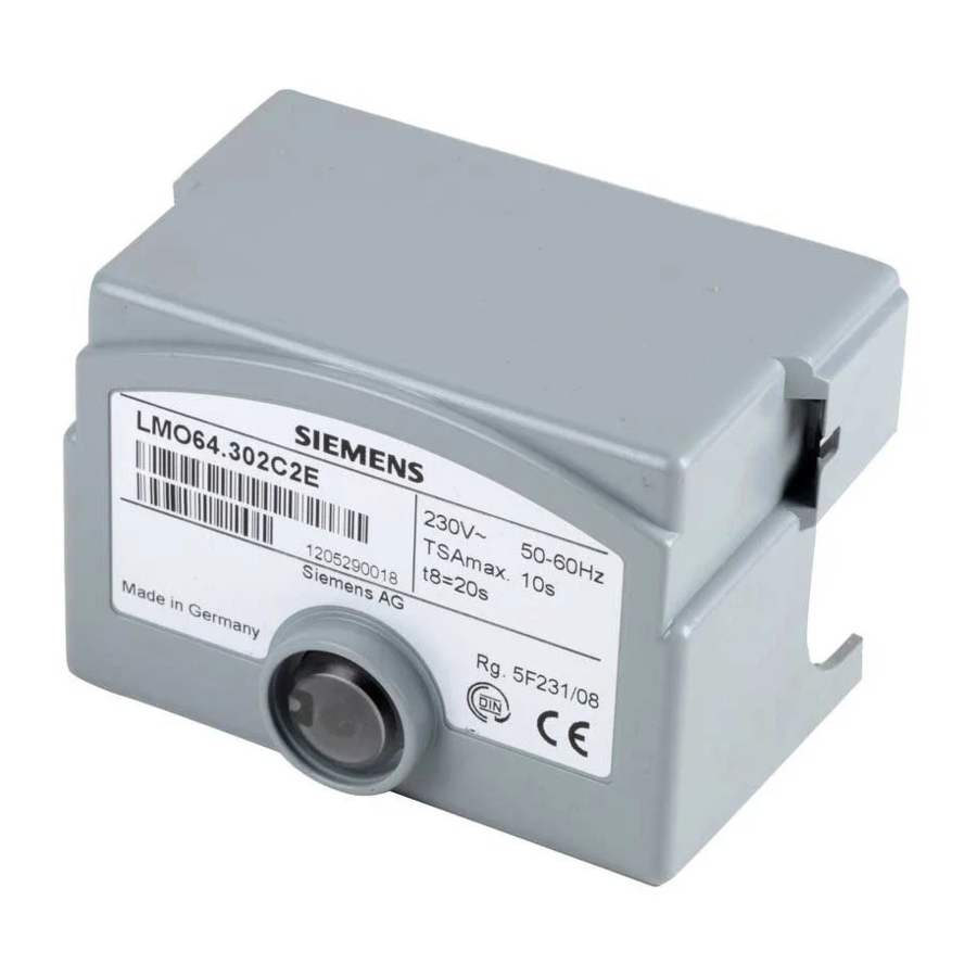
Oil Burner Controls
Microcontroller-based oil burner controls for the startup, supervision and control
of forced draft oil burners in intermittent operation. Maximum oil throughput up
to 30 kg/h.
The LMO64... and this Data Sheet are intended for use by OEMs which integrate
the burner controls in their products.
The LMO64... burner controls are designed for the startup and supervision of 1-stage
forced draft oil burners in intermittent operation. Yellow-burning flames are supervised
with photo resistive detectors QRB..., blue-burning flames with blue-flame detectors
QRC...
Applications in accordance with EN 267:
fuels
Type-tested and approved in accordance with DIN EN 298
Undervoltage detection
Electrical remote reset
Bridging contact for oil preheater
Monitoring of time for oil preheater
Accurate and reproducible program sequence through digital signal handling
Controlled intermittent operation after 24 hours of continuous operation
Limitation of the number of repetitions
Multicolor indication of fault and status messages
Postpurge function for clearing the combustion chamber after burner operation
Automatic forced draft burners for liquid
Building Technologies Division
7
138
LMO64...
Advertisement

Related Manuals for Siemens LMO64 Series


Summary of Contents for Siemens LMO64 Series
- Page 1 LMO64... Oil Burner Controls Microcontroller-based oil burner controls for the startup, supervision and control of forced draft oil burners in intermittent operation. Maximum oil throughput up to 30 kg/h. The LMO64... and this Data Sheet are intended for use by OEMs which integrate the burner controls in their products.
- Page 2 Supplementary documentation Type of documentation Product type Documentation number Environmental declaration LMO... E7130 Software documentation ACS410 J7352 Data sheet OCI400 N7614 Data sheet QRB1... N7714 Data sheet QRC1... N7716 Warning notes To avoid injury to persons, damage to property or the environment, the following warning notes must be observed! Do not open, interfere with or modify the unit! ...
- Page 3 Electrical connection of the flame detector It is important to achieve practically disturbance- and loss-free signal transmission: Never run the detector cable together with other cables – Line capacitance reduces the magnitude of the flame signal – Use a separate cable ...
- Page 4 ISO 9001:2008 ISO 14001:2004 OHSAS 18001:2007 China RoHS Hazardous substances table: http://www.siemens.com/download?A6V10883536 Service notes The service adapters can only be used for a short time. They may only be used in supervised operation by qualified staff. Life cycle Burner controls has a designed lifetime* of 250,000 burner startup cycles which, under normal operating conditions in heating mode, correspond to approx.
- Page 5 Disposal notes The unit contains electrical and electronic components and must not be disposed of together with domestic waste. Local and currently valid legislation must be observed. Mechanical design The housing is made of impact-proof, heat-resistant and flame-retarding plastic. It is of plug-in design and engages audibly in the base. Burner controls type LMO64...
- Page 6 Type summary Article no. Type reference Mains Fuel valve Burner ¹) Remote Times voltage stages capacity reset t1 / t1´ max. min. max. min. max. max. BPZ:LMO64.300C2 LMO64.300C2 AC 230 V <30 kg/h 2.5 s 15 / 16 s 10 s 15 s 10 s...
- Page 7 Test adapter (to be ordered separately) Test adapter KF8833 For checking the functions of burner controls on the burner With signal lamps for program indication With one pair of jacks for measuring the flame detector current Test adapter KF8840 ...
- Page 8 Accessories (to be ordered separately) Connection accessories for small burner controls Plug-in base AGK11.6 Plug-in base grey for connecting the LMO to burner plant Refer to Data Sheet N7201 Cable holders AGK66… For plug-in base AGK11. Refer to Data Sheet N7201 Cable holders AGK65…...
- Page 9 Technical data General unit data Mains voltage AC 230 V +10 % / -15 % Mains frequency 50...60 Hz ±6 % External primary fuse (Si) 6.3 A (slow) Power consumption 12 VA Perm. mounting position Optional Weight Approx. 200 g Safety class I (burner control with plug-in base) Degree of protection...
- Page 10 Technical data (cont´d) Flame supervision with Required detector current Perm. detector current Possible detector current QRB... and QRC... (with flame) (without flame) with flame (typically) QRB... ¹) Min. 45 µA Max. 5.5 µA Max. 100 µA QRC... ¹) Min. 70 µA Max.
- Page 11 Function Preconditions for Burner control is reset startup Reset button «EK1» «EK2» not used All contacts in the line are closed, heat demand No undervoltage Flame detector is darkened and there is no extraneous light ...
- Page 12 Operation, display, diagnostics Operation Lockout reset button «EK» is the key operating element for resetting the burner control and for activating / deactivating the diagnostic functions. The multicolor signal lamp (LED) in the lockout reset button is the key Yellow indicating element for visual diagnostics and interface diagnostics.
- Page 13 Operation, display, diagnostics (cont´d) Diagnostics of After lockout, the red fault signal lamp remains steady on. In that condition, the visual cause of fault diagnostics of the cause of fault according to the error code table can be activated by pressing the lockout reset button for more than 3 seconds.
- Page 14 Connection diagram and internal diagram µC control µC2 µC1 7138a01e/0908 Control sequence A´ t1´ Only with LMO64.302: reignition 7138d01fr/0516 8/16 Building Technologies Division CC1N7138en 18.05.2016...
- Page 15 Legend Alarm device Fuel valve BV... Lockout reset button Remote lockout reset button Flame signal Flame signal amplifier Contacts of control relay K... Cable link (required only when oil preheater is not used) 3-color signal lamps Burner motor Release contact of oil preheater Oil preheater Photo resistive detector Blue-flame detector...
- Page 16 Dimensions Dimensions in mm LMO64... Plug-in base AGK11.6 41,6 2016 Siemens AG Building Technologies Division, Berliner Ring 23, D-76437 Rastatt Subject to change! 10/16 Building Technologies Division CC1N7138en 18.05.2016...
Need help?
Do you have a question about the LMO64 Series and is the answer not in the manual?
Questions and answers