
Summary of Contents for ILX Lightwave MPS-8033 Series
- Page 1 (217) 352-9330 | Click HERE Find the Newport / ILX Lightwave MPS-8033 at our website:...
- Page 2 User’s Guide Precision Fiber Optic Sources MPS-8033 Series ILX Lightwave Corporation P. O. Box 6310 Bozeman, MT, U.S.A. 59771 · · · U.S. & Canada 1-800-459-9459 · International Inquiries: 406-586-1244 Fax 406-586-9405 · E-mail: support@ilxlightwave.com www.ilxlightwave.com 700352_7/01 Artisan Technology Group - Quality Instrumentation ... Guaranteed | (888) 88-SOURCE | www.artisantg.com...
- Page 3 Artisan Technology Group - Quality Instrumentation ... Guaranteed | (888) 88-SOURCE | www.artisantg.com...
-
Page 4: Table Of Contents
MPS-8033 Broadband Source Specifications ......4 General MPS-8033 Series Specifications ......5 MPS-8033 Artisan Technology Group - Quality Instrumentation ... - Page 5 TA B L E O F C O N T E N T S Chapter 2 Local Operation Installation ............7 Safety Considerations .
- Page 6 TA B L E O F C O N T E N T S Configuring the GPIB Controller ........20 Changing Operation from Local to Remote .
- Page 7 TA B L E O F C O N T E N T S Chapter 4 Command Reference Notes about Syntax ..........37 Commands and Queries .
- Page 8 TA B L E O F C O N T E N T S Appendix B Quick Start Guide Installation ............87 Operation .
- Page 9 Artisan Technology Group - Quality Instrumentation ... Guaranteed | (888) 88-SOURCE | www.artisantg.com...
-
Page 10: List Of Figures
List of Figures Figure 1.1 MPS-8033/55 and 65 Output Spectrums ....2 Figure 2.1 8033 Front Panel ........9 Figure 2.2 Mode Section . - Page 11 Artisan Technology Group - Quality Instrumentation ... Guaranteed | (888) 88-SOURCE | www.artisantg.com...
-
Page 12: List Of Tables
IST OF ABLES Table 1.1 Available Options........3 Table 1.2 Accessories . - Page 13 Artisan Technology Group - Quality Instrumentation ... Guaranteed | (888) 88-SOURCE | www.artisantg.com...
-
Page 14: Safety And Warranty Information
• Prolonged storage under adverse conditions • Failure to perform intended measurements or functions If necessary, return the instrument to ILX Lightwave, or authorized local ILX Lightwave distributor, for service or repair to ensure that safety features are maintained (see the contact information on page xiv). -
Page 15: Safety Symbols
Technical specifications including electrical ratings and weight are included within the manual. See the Table of Contents to locate the specifications and other product information. The following classifications are standard across all ILX Lightwave products: • Indoor use only • Ordinary Protection: This product is NOT protected against the harmful ingress of moisture. -
Page 16: Warranty
Returning an Instrument If an instrument is to be shipped to ILX Lightwave for repair or service, be sure to: Obtain a Return Authorization number (RA) from ILX Customer Service. Attach a tag to the instrument identifying the owner and indicating the required service or repair. -
Page 17: Comments, Suggestions, And Problems
C H A P T E R Comments, Suggestions, and Problems To ensure that you get the most out of your ILX Lightwave product, we ask that you direct any product operation or service related questions or comments to ILX Lightwave Customer Support. -
Page 18: Introduction And Specifications
High output stability for all options is achieved by using ILX Lightwave’s proven laser diode current and temperature control technology. Each MPS−8033 comes with a standard GPIB interface and to close the loop with other lab measurement instruments, the instrument provides a TTL compatible trigger which is synchronized with the output of the internally modulated signal. -
Page 19: Safety Considerations
1550nm and spread over a 40 nm spectral width. High output stability is achieved by using ILX Lightwave’s proven laser diode current and temperature control technology. Due to the nature of the light source, the output is intrinsically unpolarized. Select the MPS−8033/55 for 10 mW of broadband output power, or the MPS−8033/65 for 20 mW. -
Page 20: Available Options And Accessories
I N T R O D U C T I O N A N D S P E C I F I C A T I O N S C H A P T E R Available Options and Accessories Available Options and Accessories Options and accessories for the MPS−8033 sources include: Table 1.1 Available Options... -
Page 21: Mps-8033 Precision Source Specifications
I N T R O D U C T I O N A N D S P E C I F I C A T I O N S C H A P T E R Available Options and Accessories MPS-8033 Precision Source Specifications OUTPUT Wavelength:... -
Page 22: General Mps-8033 Series Specifications
I N T R O D U C T I O N A N D S P E C I F I C A T I O N S C H A P T E R Available Options and Accessories General MPS-8033 Series Specifications TRIGGER OUTPUT Type:... - Page 23 Artisan Technology Group - Quality Instrumentation ... Guaranteed | (888) 88-SOURCE | www.artisantg.com...
-
Page 24: Local Operation
C H A P T E R OCAL PERATION This chapter describes how to install, adjust, and operate the MPS−8033 series fiber optic sources. It is divided into five sections covering installation, power−up, front panel and rear panel controls, and general operation. -
Page 25: Ac Power Considerations
L O C A L O P E R A T I O N C H A P T E R Installation AC Power Considerations The 8033 can be configured to operate at nominal line voltages of 100, 120, 220, or 240 VAC. Normally, this configuration is done at the factory and need not be changed before operating the instrument. -
Page 26: Introduction To The Mps-8033 Front Panel
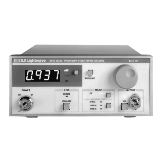
L O C A L O P E R A T I O N C H A P T E R Introduction to the MPS-8033 Front Panel Introduction to the MPS-8033 Front Panel The MPS−8033 front panel contains LED displays, switches, and a knob for control of the laser output. -
Page 27: Mode Section
L O C A L O P E R A T I O N C H A P T E R Introduction to the MPS-8033 Front Panel MODE Section When the CW switch is pressed the CW LED illuminates indicating the internal modulation function is disabled and a continuous wave output is enabled. -
Page 28: Gpib Section
L O C A L O P E R A T I O N C H A P T E R Introduction to the MPS-8033 Front Panel Press the ON switch again to turn the output off. When the output is off, the display shows the desired optical output power. -
Page 29: Gpib Address
L O C A L O P E R A T I O N C H A P T E R Introduction to the MPS-8033 Front Panel GPIB Address When the unit is in LOCAL mode, pressing the LOCAL/ADR switch causes the GPIB address to be displayed. -
Page 30: Linear (Mw) Display
L O C A L O P E R A T I O N C H A P T E R Introduction to the MPS-8033 Front Panel display to cycle through the available display modes. The enunciator at the right of the display indicates which display mode has been selected. -
Page 31: Back Panel Controls And Connections
L O C A L O P E R A T I O N C H A P T E R Back Panel Controls and Connections Back Panel Controls and Connections Refer to Figure 2.4 for the following discussions of back panel controls and connectors. TTL OUT Connector The TTL OUT connector is located in the upper left hand corner of the rear panel. -
Page 32: General Operating Procedures
L O C A L O P E R A T I O N C H A P T E R General Operating Procedures General Operating Procedures The following sections present some guidelines for operation, as well as some common operating procedures. -
Page 33: Set Reference Operation
L O C A L O P E R A T I O N C H A P T E R General Operating Procedures Set Reference Operation The reference level for the dB scale is set using the SET REFERENCE button. The following procedure indicates how to use this feature. -
Page 34: Remote Operation
C H A P T E R EMOTE PERATION GPIB (General Purpose Interface Bus) is the common name for ANSI/IEEE Standard 488.2 1987, an industry standard for interconnecting test instruments in a system. Everything you can do from the front panel can also be done remotely, and in some cases, with more flexibility. In remote operating mode, the 8033 offers all of the features accessible from the front panel. -
Page 35: Basic Gpib Concepts
R E M O T E O P E R A T I O N C H A P T E R Basic GPIB Concepts Basic GPIB Concepts The information in this basic concepts discussion is normally not necessary to successfully operate the MPS−8033 through its GPIB interface, because your computer’s GPIB controller usually handles them for you. -
Page 36: The Gpib Connector
R E M O T E O P E R A T I O N C H A P T E R Basic GPIB Concepts The GPIB Connector The standard GPIB connector consists of 16 signal lines in a 24−pin stackable connector. The extra pins are used for some twisted−pair wires. -
Page 37: Configuring The Gpib Controller
R E M O T E O P E R A T I O N C H A P T E R Basic GPIB Concepts Other GPIB features include: • A concise and straight−forward command set • Full serial poll capability, with SRQ •... -
Page 38: Command Syntax
R E M O T E O P E R A T I O N C H A P T E R Command Syntax While holding the SET REFERENCE switch, use the ADJUST knob to select the desired GPIB address. Release the SET REFERENCE switch to set the address into memory. -
Page 39: Terminators
R E M O T E O P E R A T I O N C H A P T E R Command Syntax Terminators A program message terminator identifies the end of a command string. These are the valid terminator sequences: •... -
Page 40: Substitute Parameter Names
R E M O T E O P E R A T I O N C H A P T E R Command Syntax Substitute Parameter Names For clarity in programming, the (Boolean) values of one and zero may also be represented by the appropriate substitute parameter names, as shown in Table 3.2. -
Page 41: Command Tree Stucture
R E M O T E O P E R A T I O N C H A P T E R Command Syntax Command Tree Stucture Many of the remote commands require a compound structure. This is done to distinguish between different commands of the same type. -
Page 42: Table 3.4 Invalid Syntax Command Strings
R E M O T E O P E R A T I O N C H A P T E R Command Syntax GPIB uses a flexible representation for numeric parameters: integer, floating point, or engineering/scientific notation. There are no default values for omitted parameters. Some device−dependent GPIB commands are compound commands, in which the first mnemonic opens a path to a set of commands relating to that path. -
Page 43: Status Reporting
R E M O T E O P E R A T I O N C H A P T E R Status Reporting Status Reporting Internal registers are used to inform the control program of events and conditions. The status of the MPS−8033 is held within these four internal registers: Condition: The Condition Register monitors the state of the device. -
Page 44: Register Structure And Contents
R E M O T E O P E R A T I O N C H A P T E R Status Reporting Register Structure and Contents This section provides information about the structure and contents of the different internal registers. Condition Status Register Pair Condition Status is a 16−bit register/enable−register pair with this structure: Condition Status Register... -
Page 45: Event Status Register Contents
R E M O T E O P E R A T I O N C H A P T E R Status Reporting Event Status Register Contents Event Status is a 16−bit register/enable−register pair with this structure: Evemt Status Register Copy of Status Byte 15 14 1312 11 10 7 6 5 4 3 2 1 0... -
Page 46: Standard Event Status Register
R E M O T E O P E R A T I O N C H A P T E R Status Reporting Standard Event Status Register Standard Event Status is an 8−bit register/enable−register pair with this structure: 7 6 5 4 3 2 1 0 Standard Event Status Register &... -
Page 47: Status Byte And Service Request Enable Register
R E M O T E O P E R A T I O N C H A P T E R Status Reporting Status Byte and Service Request Enable Register The Service Request Enable Register is logically ANDed to the Status Byte. If the result is non−zero, then bit #6 of the Status Byte is set to 1, and an SRQ interrupt is initiated. -
Page 48: Ansi/Ieee-488.2 Definitions
R E M O T E O P E R A T I O N C H A P T E R ANSI/IEEE-488.2 Definitions ANSI/IEEE-488.2 Definitions The following sections contain the relevant definitions for syntax diagrams and syntax elements for the GPIB commands, as defined by the IEEE−488.2 standard. -
Page 49: Advanced Programming
R E M O T E O P E R A T I O N C H A P T E R Advanced Programming Advanced Programming Once you have become familiar with the command syntax and structure, you may take advantage of some programming shortcuts which are available. -
Page 50: Error Messages
R E M O T E O P E R A T I O N C H A P T E R Error Messages Error Messages Error messages may appear on the 8033 display when error conditions occur which force the output off or reflect hardware errors in the 8033. -
Page 51: Output Off Register
R E M O T E O P E R A T I O N C H A P T E R Command Timing The output (response) data of the 8033 is sent in blocks of up to 80 bytes in length. It is sent using high speed DMA within the 8033, but may be of indefinite length. -
Page 52: Remote Interface Messages
R E M O T E O P E R A T I O N C H A P T E R Command Timing Remote Interface Messages The following sections are intended as a reference for using the 8033 with the GPIB option when an understanding of the lower level interface messages is required. - Page 53 Artisan Technology Group - Quality Instrumentation ... Guaranteed | (888) 88-SOURCE | www.artisantg.com...
-
Page 54: Chapter 4 Command Reference
C H A P T E R OMMAND EFERENCE This is a reference guide for GPIB commands that your MPS−8033 responds to, including both common and device dependent commands. It contains a reference section for all of the device− dependent commands, including those which may only be accessed via remote operation. Therefore, it is of primary interest to users who wish to utilize the GPIB option. -
Page 55: Commands And Queries
C O M M A N D R E F E R E N C E C H A P T E R Notes about Syntax Commands and Queries There are two types of device communication: commands, which tell the device to do something and do not return anything;... -
Page 56: Gpib Command Reference Summary
C O M M A N D R E F E R E N C E C H A P T E R Notes about Syntax GPIB Command Reference Summary This section contains all of the device−dependent commands for the 8033, listed in alphabetical order. - Page 57 C O M M A N D R E F E R E N C E C H A P T E R Notes about Syntax Table 4.1 Command Reference Parameters Name Expected Function Used to set the optical output power. LAS:POW NONE Returns the output power in the selected display units.
-
Page 58: Command Paths
C O M M A N D R E F E R E N C E C H A P T E R Notes about Syntax Command Paths The 8033 commands are structured in a tree format as shown in Figure 4.2. Each of the legal paths is listed below, followed by its list of path options, each of which is followed by the commands themselves. -
Page 59: Gpib Command Reference
C O M M A N D R E F E R E N C E C H A P T E R GPIB Command Reference GPIB Command Reference The following pages contain a reference for all MPS−8033 GPIB commands. This reference contains useful information for both local and remote operation of the 8033. - Page 60 C O M M A N D R E F E R E N C E C H A P T E R GPIB Command Reference CAL: OMMON EVICE EPENDENT RONT ANEL The CAL: command path is used to get to the MPS−8033’s laser output calibration commands. The following commands can be reached directly from the CAL: command path.
- Page 61 C O M M A N D R E F E R E N C E C H A P T E R GPIB Command Reference CAL:USER1 OMMON EVICE EPENDENT RONT ANEL The CAL:USER1 command will cause the 8033 to set the first calibration point into memory. Parameters None.
- Page 62 C O M M A N D R E F E R E N C E C H A P T E R GPIB Command Reference Action Clears status event registers: Event Status, Event Status Enable, and Error Queue. Note Useful to clear registers before enabling service requests (SRQ).
- Page 63 C O M M A N D R E F E R E N C E C H A P T E R GPIB Command Reference DISplay? OMMON EVICE EPENDENT RONT ANEL The DISplay? query returns the value shown on the display. Parameters None.
- Page 64 C O M M A N D R E F E R E N C E C H A P T E R GPIB Command Reference ENABle:COND OMMON EVICE EPENDENT RONT ANEL The ENABle:COND command sets the condition status enable register for the 8033. This register is a filter which is logically ANDed to the condition register.
- Page 65 C O M M A N D R E F E R E N C E C H A P T E R GPIB Command Reference ENABle:EVEnt OMMON EVICE EPENDENT RONT ANEL The ENABle:EVEnt command sets the status event enable register for the 8033. This register is a filter which is logically ANDed to the event register.
- Page 66 C O M M A N D R E F E R E N C E C H A P T E R GPIB Command Reference ENABle:OUTOFF OMMON EVICE EPENDENT RONT ANEL The ENABle:OUTOFF command sets the outoff register for the 8033. This register is a filter which allows certain conditions to turn off the laser output.
- Page 67 C O M M A N D R E F E R E N C E C H A P T E R GPIB Command Reference *ESE <nrf value> OMMON EVICE EPENDENT Event Status Enable RONT ANEL Action Enables bits in the standard event status enable register. Response The value must be between 0 and 255.
- Page 68 C O M M A N D R E F E R E N C E C H A P T E R GPIB Command Reference *ESE? OMMON EVICE EPENDENT Event Status Enable? RONT ANEL Action Requests the value in the standard event status enable register. Response The value must be between 0 and 255.
- Page 69 C O M M A N D R E F E R E N C E C H A P T E R GPIB Command Reference *ESR? OMMON EVICE EPENDENT Standard Event Status Register? RONT ANEL Action Requests the value in the standard event status register. Response The value must be between 0 and 255.
- Page 70 C O M M A N D R E F E R E N C E C H A P T E R GPIB Command Reference EVEnt? OMMON EVICE EPENDENT RONT ANEL The EVEnt? query returns the value of the status event register. Parameters None.
- Page 71 C O M M A N D R E F E R E N C E C H A P T E R GPIB Command Reference LASer:DEC OMMON EVICE EPENDENT RONT ANEL The LASer:DEC command decrements the laser output power by the preset STEP value. Parameters None.
- Page 72 C O M M A N D R E F E R E N C E C H A P T E R GPIB Command Reference LASer:MODulation:CW OMMON EVICE EPENDENT RONT ANEL The LASer:MODulation:CW command selects the continuous wave mode. Parameters None.
- Page 73 C O M M A N D R E F E R E N C E C H A P T E R GPIB Command Reference LASer:MODulation:FREQ? OMMON EVICE EPENDENT RONT ANEL The LASer:MODulation:FREQ? query returns the value of the internal modulation frequency. Parameters None.
- Page 74 C O M M A N D R E F E R E N C E C H A P T E R GPIB Command Reference LASer:OUTput? OMMON EVICE EPENDENT RONT ANEL The LASer:OUTput? query returns the output on/off status. Parameters None.
- Page 75 C O M M A N D R E F E R E N C E C H A P T E R GPIB Command Reference LASer:POWer? OMMON EVICE EPENDENT RONT ANEL The LASer:POWer? query returns the optical output power in the units of the present display mode. Parameters None.
- Page 76 C O M M A N D R E F E R E N C E C H A P T E R GPIB Command Reference LASer:REFerence? OMMON EVICE EPENDENT RONT ANEL The LASer:REFerence? query returns the reference power in the units of the present display mode. Parameters None.
- Page 77 C O M M A N D R E F E R E N C E C H A P T E R GPIB Command Reference LASer:STEP? OMMON EVICE EPENDENT RONT ANEL The LASer:STEP? query returns the step size in the units of the present display mode. Parameters None.
- Page 78 C O M M A N D R E F E R E N C E C H A P T E R GPIB Command Reference MODE: OMMON EVICE EPENDENT RONT ANEL The MODE: command path is used to get to the MPS−8033’s display control commands. The following commands can be reached directly from the MODE: command path.
- Page 79 C O M M A N D R E F E R E N C E C H A P T E R GPIB Command Reference MODE:DBM OMMON EVICE EPENDENT RONT ANEL The MODE:DBM command activates the dBm display mode. The dBm scale is defined as decibels from a 1 mW reference.
- Page 80 C O M M A N D R E F E R E N C E C H A P T E R GPIB Command Reference MODE:Watt? OMMON EVICE EPENDENT RONT ANEL The MODE:Watt? query returns the status of the DISPLAY mode with regard to the mW scale. Parameters None.
- Page 81 C O M M A N D R E F E R E N C E C H A P T E R GPIB Command Reference *OPC? OMMON EVICE EPENDENT Operation Complete Query RONT ANEL Action Places an ASCII character 1 into the intrument’s Output Queue when all pending operations have been finished.
- Page 82 C O M M A N D R E F E R E N C E C H A P T E R GPIB Command Reference *PRE? OMMON EVICE EPENDENT RONT ANEL Action Determines the contents of the PARALLEL POLL ENABLE REGISTER. Response The value must be between 0 and 65535.
- Page 83 C O M M A N D R E F E R E N C E C H A P T E R GPIB Command Reference Action Requests the state of the power−on status clear flag. Response The enable registers are saved through power OFF/ON. The enable registers are cleared during power ON.
- Page 84 C O M M A N D R E F E R E N C E C H A P T E R GPIB Command Reference *PUD? OMMON EVICE EPENDENT RONT ANEL Action Requests the factory−stored identification string. Response (sample) #2218210123413YN091201XXX Arbitrary block data string identifier 21 digits in this string...
- Page 85 C O M M A N D R E F E R E N C E C H A P T E R GPIB Command Reference *SRE <nrf value> OMMON EVICE EPENDENT Service Request Enable RONT ANEL Action Enables bits in the service request enable register. Values Standard Event Summary (ESB) (MAV) Message Available...
- Page 86 C O M M A N D R E F E R E N C E C H A P T E R GPIB Command Reference *STB? OMMON EVICE EPENDENT Status Byte? RONT ANEL Action Requests the value in the status byte register. Values Standard Event Summary (ESB) (MAV) Message Available...
- Page 87 C O M M A N D R E F E R E N C E C H A P T E R GPIB Command Reference TERM OMMON EVICE EPENDENT RONT ANEL The TERM command allows the programmer to select the message terminator type for GPIB messages.
- Page 88 C O M M A N D R E F E R E N C E C H A P T E R GPIB Command Reference TIME? OMMON EVICE EPENDENT RONT ANEL The TIME? query allows the programmer to determine how much time has passed since the 8033 was last powered up.
-
Page 89: Error Messages
C O M M A N D R E F E R E N C E C H A P T E R Programming Examples Error Messages Error messages may appear on the display when error conditions occur in the 8033. In remote operation, the current error list can be read by issuing the "ERR?"... -
Page 90: Programming Example: An Mps-8033 Driver
C H A P T E R Programming Examples Programming Example: An MPS-8033 Driver Mps8033dvr(Device_id,Command$,Response$,Err$) ’ A subroutine to drive the ILX Lightwave MPS−8033 Fiber Optic Source. This driver ’ provides bus timeout protection and looks for device dependent errors. -
Page 91: Programming Example: Laser Output Turn On Subroutine
C H A P T E R Programming Examples Programming Example: Laser output turn on subroutine SUB Turnon8033(Device_id,On_ok%) ’ A subroutine to turn on the laser in the ILX Lightwave MPS−8033 Fiber Optic Source. CALL Mps8033dvr(Device_id,"LAS:OUT ’ Turn on laser ON",Response$,Err$) - Page 92 C H A P T E R AINTENANCE This chapter describes how to maintain the MPS−8033. Included are sections covering calibration, fuse replacement, line voltage selection, and disassembly. THE SERVICE PROCEDURES DESCRIBED IN THIS CHAPTER ARE FOR USE BY QUALIFIED PERSONNEL ONLY. POTENTIALLY LETHAL VOLTAGES EXIST WITHIN THE MPS−8033.
-
Page 93: Calibration Overview
Table 5.1 Recommended Test Equipment for Calibration Description Mfg./Model Specification Optical Power Meter ILX Lightwave OMM−6810B Power Range .100 to 100 mW Fiber Optic Patch Cord SMF with FC/APC Connector, 3 meters Environmental Conditions Calibrate the instrument under nominal laboratory conditions. We recommend calibration at 23 °C ±1.0 °C. -
Page 94: Local Operation Optical Power Calibration
M A I N T E N A N C E C H A P T E R Calibration Overview Local Operation Optical Power Calibration The following procedure is for manual calibration of the MPS−8033 optical output power. Remote calibration is discussed in Remote Operation Optical Power Calibration on page 78. The instrument utilizes a 3−point calibration to characterize the power response of the source’s laser diode. -
Page 95: Remote Operation Optical Power Calibration
M A I N T E N A N C E C H A P T E R Calibration Overview Remote Operation Optical Power Calibration The following procedure is for calibration of the MPS−8033 optical power via GPIB. The 8033 utilizes a 3−point calibration to characterize the power response of the internal laser diode. -
Page 96: Recalling The Factory Calibration
CAL:RECALL When this command is issued the present calibration values are lost and the default calibration is reset. ILX Lightwave recommends a user calibration after you execute this command. Cleaning the Internal Fiber Optic Connector Occasionally the fiber optic output connector on the 8033 becomes dirty. This section describes two procedures for cleaning the end of the output fiber. -
Page 97: Fuse Replacement
M A I N T E N A N C E C H A P T E R Calibration Overview Second method: this procedure requires some disassembly of the 8033 and should be performed with caution. Make sure that the instrument is off and unplugged before beginning this procedure. Lay the instrument on its side, remove the two screws securing the bottom panel and remove the panel. -
Page 98: Hardware Troubleshooting Guide
C H A P T E R ROUBLESHOOTING This chapter is intended to be used as a guide when the MPS−8033 does not perform as expected. It is not a service manual, rather a guide to alleviating basic problems that can arise during operation. -
Page 99: Gpib Troubleshooting Guide
T R O U B L E S H O O T I N G C H A P T E R Hardware Troubleshooting Guide Table 6.1 Hardware Troubleshooting Symptoms Causes and Corrective Actions Output is on but there is no Check the patch cord and the connection with the 8033 and other test •... -
Page 100: Error Message Reference
A P P E N D I X RROR ESSAGES When errors occur, messages may appear on the 8033 display. In remote operation, the current error list can be read by issuing the "ERR?" query. When this is done, a string will be returned containing all of the error messages which are currently in the error message queue. -
Page 101: Table A.1 Error Code Classifications
C H A P T E R Error Message Reference The errors codes are numerically divided into areas of operation. Errors which pertain to the following areas are listed in the ranges shown in Table A.1. Table A.1 Error Code Classifications Error Code Range Area of Operation E−001 to E−099... - Page 102 C H A P T E R Error Message Reference Table A.2 Error Code Descriptions Error Code Explanation E−202 <PROGRAM DATA> will not convert to valid type. E−203 Security violation, command is not available without clearance. E−204 <PROGRAM DATA> suffix type is not valid. E−205 <PROGRAM DATA>...
- Page 103 Artisan Technology Group - Quality Instrumentation ... Guaranteed | (888) 88-SOURCE | www.artisantg.com...
- Page 104 A P P E N D I X UICK TART UIDE This chapter contains information that allows you to quickly install, configure, and operate the MPS− 8033. Installation Check to make sure the voltage printed on the back panel of the instrument matches the power−line voltage in your area.
-
Page 105: More Information
C H A P T E R Operation Operation The following paragraphs briefly explain the operation of each function of the MPS−8033. DISPLAY Use the DISPLAY switch to toggle the display units between linear scale (mW), log scale relative to 1 mW (dBm) and log scale relative to a user defined reference (dB). -
Page 106: Configuring The National Instruments Ni-488.2 Gpib Controller
A P P E N D I X GPIB S YSTEM ONTROLLER ONFIGURATION This appendix provides a guide for setting up the GPIB System Controller for remote control of the MPS−8033. Routine GPIB operation is described in Chapter 3, Remote Operation and Chapter 4, Command Reference. - Page 107 Artisan Technology Group - Quality Instrumentation ... Guaranteed | (888) 88-SOURCE | www.artisantg.com...
-
Page 108: Index
NDEX device dependent commands 19, 21, 24, 37 device dependent message 18 AC Power 8, 9, 14 disassembly 75, 80 ADJUST knob 9, 12, 15, 88 display 9, 12, 13 ADJUST section 12 ANSI/IEEE Standard 488.2 17, 31 enable register 26, 29 environmental conditions 76 back panel 80 error display 13... - Page 109 I N D E X GPIB 17, 18 OCIS 67 address 12, 20 operating 7, 15 basic concepts 18 operation complete 30, 63, 71 cable connections 18 OQIS 67 command types 42 output off 49 commands 21, 24, 37, 38 enable register 34 connector 14 forced 33...
- Page 110 I N D E X safety 2, 7 sequential/overlapped commands 33 service request enable register 29, 30 service, contact information xiv SET REFERENCE switch 9 setting references 16 specifications broadband source 4 general 5 precision source 4 standard event status register 29 status byte 26, 29, 30 suffix 37 suffix unit 23...
- Page 111 I N D E X MPS-8033 Artisan Technology Group - Quality Instrumentation ... Guaranteed | (888) 88-SOURCE | www.artisantg.com...
Need help?
Do you have a question about the MPS-8033 Series and is the answer not in the manual?
Questions and answers