
Related Manuals for Galil Motion Control DMC-1000


Summary of Contents for Galil Motion Control DMC-1000
- Page 1 (217) 352-9330 | Click HERE Find the Galil Motion Control DMC-1040 at our website:...
- Page 2 USER MANUAL DMC-1000 Manual Rev. 2.0xf By Galil Motion Control, Inc. Galil Motion Control, Inc. 270 Technology Way Rocklin, California 95765 Phone: (916) 626-0101 Fax: (916) 626-0102 Internet Address: support@galilmc.com URL: www.galilmc.com Rev 6/06 Artisan Technology Group - Quality Instrumentation ... Guaranteed | (888) 88-SOURCE | www.artisantg.com...
- Page 3 Your DMC-1000 motion controller has been designed to work with both servo and stepper type motors. In addition, the DMC-1000 has a daughter board for controllers with more than 4 axes. Installation and system setup will vary depending upon whether the controller will be used with stepper motors, or servo motors, and whether the controller has more than 4 axes of control.
- Page 4 Firmware Updates New feature for Rev 2.0h February 1998: Feature Description 1. CMDERR enhanced to support multitasking If CMDERR occurs on thread 1,2 or 3, thread will be holted. Thread can be re-started with XQ_ED2,_ED1, 1 for retry XQ_ED3,_ED1, 1 for next instruction 2.
- Page 5 1. Operand ‘&’ and ‘|’ for conditional statements Allows for multiple conditional statements in jump routines IE. (A>=3) & (B<55) | (C=78) New feature for Rev 2.0 March 1996. (This revision is also designated DMC-1000-18). Feature Description 1. DAC resolution increased to 16-bits.
- Page 6 KPZ=10 Set Z axis gain to 10 KP*=10 Set all axes gains to 10 (KPXZ=10 is invalid. Only one or all axes can be specified at a time). New commands added July 1993 Rev 1.2: Command Description Gives available variables Give available labels @COM[n] 2's complement function...
- Page 7 Artisan Technology Group - Quality Instrumentation ... Guaranteed | (888) 88-SOURCE | www.artisantg.com...
-
Page 8: Table Of Contents
Elements You Need ........................6 Installing the DMC-1000......................7 Step 1. Determine Overall Motor Configuration............7 Step 2. Configure Jumpers on the DMC-1000 ............7 Step 3. Install the DMC-1000 in the Computer............8 Step 4. Install Communications Software ..............8 Step 5. - Page 9 Interrogating the Controller .....................43 Interrogation Commands ...................43 Additional Interrogation Methods................44 Operands........................44 Command Summary ....................44 Chapter 6 Programming Motion Overview..........................45 Independent Axis Positioning....................45 ii • Contents DMC-1000 Artisan Technology Group - Quality Instrumentation ... Guaranteed | (888) 88-SOURCE | www.artisantg.com...
- Page 10 Homing ............................ 78 High Speed Position Capture (Latch) ..................81 Chapter 7 Application Programming Overview ..........................83 Using the DMC-1000 Editor to Enter Programs ..............83 Edit Mode Commands....................84 Program Format ........................85 Using Labels in Programs ..................85 Special Labels......................
- Page 11 Programmable Position Limits ................126 Off-On-Error ......................127 Automatic Error Routine ..................127 Limit Switch Routine....................127 Chapter 9 Troubleshooting Overview..........................129 Installation ..........................129 Communication........................130 Stability..........................130 Operation ..........................130 iv • Contents DMC-1000 Artisan Technology Group - Quality Instrumentation ... Guaranteed | (888) 88-SOURCE | www.artisantg.com...
- Page 12 J4 - Driver (20 pin IDC)..................162 J5 - General I/O (26 pin IDC) ................. 162 Connectors are the same as described in section entitled “Connectors for DMC-1000 Main Board”. see pg. 146..................162 JX6, JY6, JZ6, JW6 - Encoder Input (10 pin IDC) ..........162 ICM-1100 Drawing .......................
- Page 13 Elements You Need ........................6 Installing the DMC-1000 ......................7 Step 1. Determine Overall Motor Configuration............7 Step 2. Configure Jumpers on the DMC-1000 ............7 Step 3. Install the DMC-1000 in the Computer............8 Step 4. Install Communications Software ..............9 Step 5. Establish Communications with Galil Communication Software ....9 Changing the I/O Address of the Controller..............10...
- Page 14 Controller Response to DATA ....................42 Interrogating the Controller ..................... 43 Interrogation Commands ................... 43 Additional Interrogation Methods................43 Operands........................44 Command Summary....................44 Contents • vii DMC-1000 Artisan Technology Group - Quality Instrumentation ... Guaranteed | (888) 88-SOURCE | www.artisantg.com...
- Page 15 Using the KS Command (Step Motor Smoothing):...........77 Homing ............................78 High Speed Position Capture (Latch) ..................81 Chapter 7 Application Programming Overview..........................83 Using the DMC-1000 Editor to Enter Programs..............83 Edit Mode Commands ....................84 Program Format ........................85 Using Labels in Programs ..................85 Special Labels......................86 Commenting Programs ....................86...
- Page 16 Programmable Position Limits ................126 Off-On-Error ......................126 Automatic Error Routine ..................127 Limit Switch Routine ....................127 Chapter 9 Troubleshooting Overview ..........................129 Contents • ix DMC-1000 Artisan Technology Group - Quality Instrumentation ... Guaranteed | (888) 88-SOURCE | www.artisantg.com...
- Page 17 J3 - Aux Encoder (20 pin IDC) ................161 J4 - Driver (20 pin IDC) ..................161 J5 - General I/O (26 pin IDC)..................161 Connectors are the same as described in section entitled “Connectors for DMC-1000 Main Board”. see pg. 146 ..................162 x • Contents DMC-1000 Artisan Technology Group - Quality Instrumentation ...
- Page 18 Pinouts for DB-10096 Connectors ..................168 J1 Pinout........................168 J2 Pinout........................169 Coordinated Motion - Mathematical Analysis............... 170 DMC-600/DMC-1000 Comparison..................173 DMC-600/DMC-1000 Command Comparison ............174 DMC-600/DMC-1000 Pin-out Conversion Table........... 177 List of Other Publications...................... 179 Contacting Us ........................179 WARRANTY ........................180 Index Contents •...
- Page 19 Artisan Technology Group - Quality Instrumentation ... Guaranteed | (888) 88-SOURCE | www.artisantg.com...
-
Page 20: Chapter 1 Overview
Designed for maximum system flexibility, the DMC-1000 is available for one, two, three or four axes configuration per card. An add-on card is available for control of five, six, seven or eight axes. The DMC-1000 can be interfaced to a variety of motors and drives including step motors, servo motors and hydraulic systems. -
Page 21: Standard Servo Motors With +/- 10 Volt Command Signal
Chapter 2 describes the proper connection and procedure for using stepper motors. DMC-1000 Functional Elements The DMC-1000 circuitry can be divided into the following functional groups as shown in Figure 1.1 and discussed in the following. To Host... -
Page 22: Microcomputer Section
Controllers with 5 or more axes provide 24 inputs and 16 outputs. 1080 System Elements As shown in Fig. 1.2, the DMC-1000 is part of a motion control system which includes amplifiers, motors and encoders. These elements are described below. Power Supply... -
Page 23: Motor
AEN output will go low. The error light for each axis will also turn on at this stage. A reset is required to restore the DMC-1000 to normal operation. Consult the factory for a Return Materials Authorization (RMA) Number if your DMC-1000 is damaged. -
Page 24: Chapter 2 Getting Started
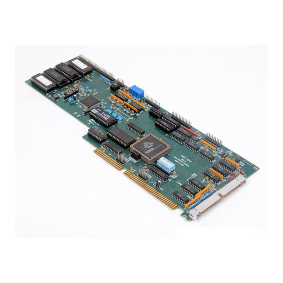
Chapter 2 Getting Started The DMC-1000 Motion Controller Figure 2-1 - DMC-1000 1A/1B DMC-1000 ROM. These are labeled with 60-pin header connector for the main output the firmware revision that you have cable of the DMC-1000 received. For example, a label may be affixed to the ROM that specifies the firmware revision such as ‘2.0c’. -
Page 25: Elements You Need
Elements You Need Before you start, you will need the following system elements: 1. DMC-1000 Motion Controller and included 60-pin ribbon cable. Also included is a 26-pin ribbon cable for general I/O. 1a. For stepper motor operation, you will need an additional 20-pin ribbon cable for J4. -
Page 26: Installing The Dmc-1000
Step 2. Configure Jumpers on the DMC-1000 The DMC-1000 has jumpers inside the controller box which may need to be installed. To access these jumpers, the cover of the controller box must be removed. The following describes each of the jumpers. -
Page 27: Step 3. Install The Dmc-1000 In The Computer
Bypassing the Opto-Isolation in Chapter 3. Step 3. Install the DMC-1000 in the Computer. The DMC-1000 is installed directly into the ISA expansion bus. The procedure is outlined below. Step A. Make sure the PC is in the power-off condition and unplug power cord from PC. -
Page 28: Step 4. Install Communications Software
Pressing the down arrow to the right of this field will reveal a menu of valid controller types. You should choose DMC-1000. Note that the default I/O address of 1000 appears. This does not need to be changed unless the address on the controller was changed. You will also need to supply an interrupt if you want to use the interrupt capabilities of the controller. -
Page 29: Changing The I/O Address Of The Controller
If the address 1000 is not available, Galil recommends using the address 816, as it is likely to be available. Changing the I/O address at which the DMC-1000 resides is a two step process. First, you must configure the address of the controller card physically using the Address DIP Switches located on the card (see “Your DMC-1000”... -
Page 30: Step 6. Connect Amplifiers And Encoders
ICM-1100’s equipped with servo amplifiers for brush type DC motors. If you are using an ICM-1100, connect the 100-pin ribbon cable to the DMC-1000 and to the connector located on the AMP-11X0 or ICM-1100 board. The ICM-1100 provides screw terminals for access to the connections described in the following discussion. - Page 31 The DMC-1000 accepts single-ended or differential encoder feedback with or without an index pulse. If you are not using the AMP-11X0 or the ICM-1100 you will need to consult the appendix for the encoder pinouts for connection to the motion controller.
-
Page 32: Step 7A. Connect Standard Servo Motors
Step 7a. Connect Standard Servo Motors The following discussion applies to connecting the DMC-1000 controller to standard servo motor amplifiers: The motor and the amplifier may be configured in the torque or the velocity mode. In the torque mode, the amplifier gain should be such that a 10 Volt signal generates the maximum required current. - Page 33 AEN signal to be connected from the controller to the amplifier. Step C. Set Torque Limit as a Safety Precaution To limit the maximum voltage signal to your amplifier, the DMC-1000 controller has a torque limit command, TL. This command sets the maximum voltage output of the controller and can be used to avoid excessive torque or speed when initially setting up a servo system.
- Page 34 Figure 2-2 - System Connections with the AMP-1100Amplifier. Note: this figure shows a Galil Motor and Encoder which uses a flat ribbon cable to connect to the AMP-1100 unit. Chapter 2 Getting Started • 15 DMC-1000 Artisan Technology Group - Quality Instrumentation ... Guaranteed | (888) 88-SOURCE | www.artisantg.com...
-
Page 35: Step 7B. Connect Step Motors
0.5 and 8, where 8 implies the largest amount of smoothing. See Command Reference regarding KS. The DMC-1000 profiler commands the step motor amplifier. All DMC-1000 motion commands apply such as PR, PA, VP, CR and JG. The acceleration, deceleration, slew speed and smoothing are also used. -
Page 36: Step 8. Tune The Servo System
Step A. Install SM jumpers Each axis of the DMC-1000 that will operate a stepper motor must have the corresponding stepper motor jumper installed. For a discussion of SM jumpers, see step 2. Step B. Connect step and direction signals. -
Page 37: Design Examples
DC 100000 Deceleration AC 100000 Acceleration BG X Start Motion Example 3 - Multiple Axes Objective: Move the four axes independently. 18 • Chapter 2 Getting Started DMC-1000 Artisan Technology Group - Quality Instrumentation ... Guaranteed | (888) 88-SOURCE | www.artisantg.com... -
Page 38: Example 4 - Independent Moves
Tell error - W axis only Example 6 - Absolute Position Objective: Command motion by specifying the absolute position. Instruction Interpretation Chapter 2 Getting Started • 19 DMC-1000 Artisan Technology Group - Quality Instrumentation ... Guaranteed | (888) 88-SOURCE | www.artisantg.com... -
Page 39: Example 7 - Velocity Control
The maximum level of 10 volts provides the full output torque. Example 9 - Interrogation The values of the parameters may be interrogated. Some examples … 20 • Chapter 2 Getting Started DMC-1000 Artisan Technology Group - Quality Instrumentation ... Guaranteed | (888) 88-SOURCE | www.artisantg.com... -
Page 40: Example 10 - Operation In The Buffer Mode
Label for loop PA V1 Move X motor V1 counts BG X Start X motion AM X After X motion is complete Chapter 2 Getting Started • 21 DMC-1000 Artisan Technology Group - Quality Instrumentation ... Guaranteed | (888) 88-SOURCE | www.artisantg.com... -
Page 41: Example 13 - Motion Programs With Trippoints
Command X move 1/2 the distance Start X motion After X moved WT 500 Wait 500 ms Report the value of V1 22 • Chapter 2 Getting Started DMC-1000 Artisan Technology Group - Quality Instrumentation ... Guaranteed | (888) 88-SOURCE | www.artisantg.com... -
Page 42: Example 15 - Linear Interpolation
This program moves X to an initial position of 1000 and returns it to zero on increments of half the distance. Note, _TPX is an internal variable which returns the value of the X position. Internal variables may be created by preceding a DMC-1000 instruction with an underscore, _. Example 15 - Linear Interpolation Objective: Move X,Y,Z motors distance of 7000,3000,6000, respectively, along linear trajectory. - Page 43 (-4000,4000) (0,4000) R=2000 (-4000,0) (0,0) local zero Figure 2-4 Motion Path for Example 16 24 • Chapter 2 Getting Started DMC-1000 Artisan Technology Group - Quality Instrumentation ... Guaranteed | (888) 88-SOURCE | www.artisantg.com...
-
Page 44: Chapter 3 Connecting Hardware
26-pin J5 IDC connector from the DMC-1000 to the AMP-11X0 or ICM-1100 board. If you plan to use the auxiliary encoder feature of the DMC-1000, you must also connect a 20-pin ribbon cable from the 20-pin J3 header connector on the DMC-1000 to the 26-pin J3 header connector on the AMP-11X0 or ICM-1100. -
Page 45: Home Switch Input
1 at every transition. A transition in the logic state of the Home input will cause the controller to execute a homing routine specified by the user. There are three homing routines supported by the DMC-1000: Find Edge (FE), Find Index (FI), and Standard Home (HM). -
Page 46: Uncommitted Digital Inputs
NOTE: The error LED does not light up when the Abort Input is active. Uncommitted Digital Inputs The DMC-1000 has 8 uncommitted opto-isolated inputs. These inputs are specified as INx where x specifies the input number, 1 through 24. These inputs allow the user to monitor events external to the controller. -
Page 47: Using An Isolated Power Supply
R, is needed in series with the input such that Ω 1 mA < V supply/(R + 2.2K ) < 15 mA 28 • Chapter 3 Connecting Hardware DMC-1000 Artisan Technology Group - Quality Instrumentation ... Guaranteed | (888) 88-SOURCE | www.artisantg.com... -
Page 48: Bypassing The Opto-Isolation
Figure 3-3. This can be done by connecting a jumper between the pins LSCOM or INCOM and 5V, labeled J9. These jumpers can be added on either the ICM-1100 or the DMC-1000. This can also be done by connecting wires between the 5V supply and common signals using the screw terminals on the ICM-1100 or AMP-11x0. -
Page 49: Changing Optoisolated Inputs From Active Low To Active High
The gain should be set such that a 10 Volt input results in the maximum required current. The DMC-1000 also provides an amplifier enable signal, AEN. This signal changes under the following conditions: the watchdog timer activates, the motor-off command, MO, is given, or the OE1command (Enable Off-On-Error) is given and the position error exceeds the error limit. -
Page 50: Ttl Inputs
Figure 3-4 - Connecting AEN to the motor amplifier TTL Inputs As previously mentioned, the DMC-1000 has 8 uncommitted TTL level inputs for controllers with 5 or 1080 more axes. These are specified as INx where x ranges from 17 thru 24. The reset input is also a TTL level, non-isolated signal and is used to locally reset the DMC-1000 without resetting the PC. -
Page 51: Ttl Outputs
4. There is a failure with the output IC which drives the error signal. Offset Adjustment For each axis, the DMC-1000 provides offset correction potentiometers to compensate for any offset in the analog output. These potentiometers have been adjusted at the factory to produce 0 Volts output for a zero digital motor command. -
Page 52: Chapter 4 Communication
AT style card that is mapped into the I/O space. Communication between the DMC-1000 and the computer is in the form of ASCII characters where data is sent and received via READ and WRITE registers on the DMC-1000. A handshake is required for sending and receiving data. -
Page 53: Communication With The Controller
N and the CONTROL register occupies address N+1 in the I/O space. The READ register is used for receiving data from the DMC-1000. The WRITE register is used to send data to the DMC-1000. The CONTROL register may be read or written to and is used for controlling communication, flags and interrupts. -
Page 54: Advanced Communication Techniques
To receive data from the DMC-1000, read the control register at address N+1 and check bit 5. If bit 5 is zero, the DMC-1000 has data to be read in the READ register at address N. Bit 5 must be checked for every character read and should be read until it signifies empty. -
Page 55: Interrupts
It is a good idea to clear any control data before attempting this procedure. Send a no-op instruction, by reading N+1 address, before you start. All data, including data from the DMC-1000, will then be cleared. Clearing the FIFO is useful for emergency resets or Abort. For example, to Reset the controller, clear the FIFO, then send the RS command. - Page 56 If you want an interrupt for Input 2 only, you would enable bit 15 for the m parameter and bit 1 for the n parameter. M = 2 = 32,768 N = 2 EI 32768,2 Chapter 4 Communication • 37 DMC-1000 Artisan Technology Group - Quality Instrumentation ... Guaranteed | (888) 88-SOURCE | www.artisantg.com...
-
Page 57: Servicing Interrupts
The DMC-1000 also provides 16 User Interrupts which can be sent by sending the command UI n to the DMC-1000, where n is an integer between 0 and 15. The UI command does not require the EI command. Servicing Interrupts Once an interrupt occurs, the host computer can read information about the interrupt by first writing the data 6 to the control register at address N + 1. -
Page 58: Controller Response To Data
FIFO buffer. After the instruction is decoded, the DMC-1000 returns a colon (:) if the instruction was valid or a question mark (?) if the instruction was not valid. - Page 59 THIS PAGE LEFT BLANK INTENTIONALLY 40 • Chapter 4 Communication DMC-1000 Artisan Technology Group - Quality Instrumentation ... Guaranteed | (888) 88-SOURCE | www.artisantg.com...
-
Page 60: Chapter 5 Command Basics
ST stops the motion. Commands can be sent "live" over the bus for immediate execution by the DMC-1000, or an entire group of commands can be downloaded into the DMC-1000 memory for execution at a later time. -
Page 61: Coordinated Motion With More Than 1 Axis
Controller Response to DATA The DMC-1000 returns a : for valid commands. The DMC-1000 returns a ? for invalid commands. For example, if the command BG is sent in lower case, the DMC-1000 will return a ?. :bg <enter> invalid command, lower case DMC-1000 returns a ? When the controller receives an invalid command the user can request the error code. -
Page 62: Interrogating The Controller
Interrogating the Controller Interrogation Commands The DMC-1000 has a set of commands that directly interrogate the controller. When the command is entered, the requested data is returned in decimal format on the next line followed by a carriage return and line feed. The format of the returned data can be changed using the Position Format (PF), Variable Format (VF) and Leading Zeros (LZ) command. -
Page 63: Operands
The controller can also be interrogated with operands. Operands Most DMC-1000 commands have corresponding operands that can be used for interrogation. Operands must be used inside of valid DMC expressions. For example, to display the value of an operand, the user could use the command: MG ‘operand’... -
Page 64: Chapter 6 Programming Motion
Motion is complete when the last position command is sent by the DMC-1000 profiler. Note: The actual motor motion may not be complete when the profile has been completed, however, the next motion command may be specified. -
Page 65: Command Summary - Independent Axis
The lower case specifiers (x,y,z,w) represent position values for each axis. For controllers with more than 4 axes, the position values would be represented as a,b,c,d,e,f,g,h. The DMC-1000 also allows use of single axis specifiers such as PRY=2000 or SPH=10000. Operand Summary - Independent Axis... -
Page 66: Independent Jogging
The jog mode of motion allows the user to change speed, direction and acceleration during motion. The user specifies the jog speed (JG), acceleration (AC), and the deceleration (DC) rate for each axis. Chapter 6 Programming Motion • 47 DMC-1000 Artisan Technology Group - Quality Instrumentation ... Guaranteed | (888) 88-SOURCE | www.artisantg.com... -
Page 67: Command Summary - Jogging
Note that the controller operates as a closed-loop position controller while in the jog mode. The DMC-1000 converts the velocity profile into a position trajectory and a new position target is generated every sample period. This method of control results in precise speed regulation with phase lock accuracy. -
Page 68: Linear Interpolation Mode
Loop Linear Interpolation Mode The DMC-1000 provides a linear interpolation mode for 2 or more axes (up to 8 axes for the DMC- 1080). In linear interpolation mode, motion between the axes is coordinated to maintain the prescribed vector speed, acceleration, and deceleration along the specified path. The motion path is described in terms of incremental distances for each axis. -
Page 69: Specifying Vector Acceleration, Deceleration And Speed
The commands VS n, VA n, and VD n are used to specify the vector speed, acceleration and deceleration. The DMC-1000 computes the vector speed based on the axes specified in the LM mode. For example, LM XYZ designates linear interpolation for the X,Y and Z axes. The vector speed for this example would be computed using the equation: , where XS, YS and ZS are the speed of the X,Y and Z axes. -
Page 70: Command Summary - Linear Interpolation
Specify axes for linear interpolation LM abcdefgh (same) controllers with 5 or more axes Returns number of available spaces for linear segments in DMC-1000 sequence buffer. Zero means buffer full. 512 means buffer empty. LI x,y,z,w < n Specify incremental distances relative to current position, and assign vector speed n. - Page 71 Segment counter - returns number of the segment in the sequence, starting at zero. Returns length of vector (resets after 2147483647) Returns number of available spaces for linear segments in DMC-1000 sequence buffer. Zero means buffer full. 512 means buffer empty.
- Page 72 750 incremental distances which are filled by the program #LOAD. Instruction Interpretation #LOAD Load Program DM VX [750],VY [750] Define Array Chapter 6 Programming Motion • 53 DMC-1000 Artisan Technology Group - Quality Instrumentation ... Guaranteed | (888) 88-SOURCE | www.artisantg.com...
-
Page 73: Vector Mode: Linear And Circular Interpolation Motion
Vector Mode: Linear and Circular Interpolation Motion The DMC-1000 allows a long 2-D path consisting of linear and arc segments to be prescribed. Motion along the path is continuous at the prescribed vector speed even at transitions between linear and circular segments. -
Page 74: Specifying Vector Acceleration, Deceleration And Speed
Abort (AB1) must be used to abort the coordinated motion sequence. It is the responsibility of the user to keep enough motion segments in the DMC-1000 sequence buffer to ensure continuous motion. If the controller receives no additional motion segments and no VE command, the controller will stop motion instantly at the last vector. - Page 75 Compensating for Differences in Encoder Resolution: By default, the DMC-1000 uses a scale factor of 1:1 for the encoder resolution when used in vector mode. If this is not the case, the command, ES can be used to scale the encoder counts. The ES command accepts two arguments which represent the number of counts for the two encoders used for vector motion.
-
Page 76: Command Summary - Vector Mode Motion
Ellipse scale factor. S curve smoothing constant for coordinated moves Return number of available spaces for linear and circular segments in DMC-1000 sequence buffer. Zero means buffer is full. 512 means buffer is empty. Operand Summary - Vector Mode Motion... -
Page 77: Electronic Gearing
GAG or GAH for DMC-1080) specifies the master axis. There may only be one master. GR x,y,z,w specifies the gear ratios for the slaves where the ratio may be a number between +/-127.9999 with a 58 • Chapter 6 Programming Motion DMC-1000 Artisan Technology Group - Quality Instrumentation ... Guaranteed | (888) 88-SOURCE | www.artisantg.com... -
Page 78: Command Summary - Electronic Gearing
Master axis moves 10000 counts at slew speed of 100000 counts/sec. Y is defined as the master. X,Z,W are geared to master at ratios of 5,-.5 and 10 respectively. Specify master axes as Y Chapter 6 Programming Motion • 59 DMC-1000 Artisan Technology Group - Quality Instrumentation ... Guaranteed | (888) 88-SOURCE | www.artisantg.com... - Page 79 Specify gear ratio for X axis to be 2 In applications where both the master and the follower are controlled by the DMC-1000 controller, it may be desired to synchronize the follower with the commanded position of the master, rather than the actual position.
-
Page 80: Electronic Cam
Up to 256 intervals are allowed. The size of the master interval and the starting point are specified by the instruction: Chapter 6 Programming Motion • 61 DMC-1000 Artisan Technology Group - Quality Instrumentation ... Guaranteed | (888) 88-SOURCE | www.artisantg.com... - Page 81 ECAM mode and n=0 disables ECAM mode. Step 6. Engage the slave motion To engage the slave motion, use the instruction EG x,y,z,w 62 • Chapter 6 Programming Motion DMC-1000 Artisan Technology Group - Quality Instrumentation ... Guaranteed | (888) 88-SOURCE | www.artisantg.com...
- Page 82 Y = 0.5 * X + 100 sin (0.18 * X) where X is the master, with a cycle of 2000 counts. Chapter 6 Programming Motion • 63 DMC-1000 Artisan Technology Group - Quality Instrumentation ... Guaranteed | (888) 88-SOURCE | www.artisantg.com...
- Page 83 After Y moved Wait for start signal EG,1000 Engage slave AI - 1 Wait for stop signal EQ,1000 Disengage slave 64 • Chapter 6 Programming Motion DMC-1000 Artisan Technology Group - Quality Instrumentation ... Guaranteed | (888) 88-SOURCE | www.artisantg.com...
- Page 84 ECAM cycles. The first graph is for the X axis, the second graph shows the cycle on the Y axis and the third graph shows the cycle of the Z axis. Chapter 6 Programming Motion • 65 DMC-1000 Artisan Technology Group - Quality Instrumentation ... Guaranteed | (888) 88-SOURCE | www.artisantg.com...
-
Page 85: Contour Mode
Contour Mode The DMC-1000 also provides a contouring mode. This mode allows any arbitrary position curve to be prescribed for 1 to 8 axes. This is ideal for following computer generated paths such as parabolic, spherical or user-defined profiles. The path is not limited to straight line and arc segments and the path length may be infinite. -
Page 86: Additional Commands
Figure 6.4 - The Required Trajectory Additional Commands The command, WC, is used as a trippoint "When Complete". This allows the DMC-1000 to use the next increment only when it is finished with the previous one. Zero parameters for DT followed by zero parameters for CD exit the contour mode. -
Page 87: Command Summary - Contour Mode
) sin (2 T/120) ω Note that the velocity, , in count/ms, is ω π = 50 [1 - cos 2 T/120] 68 • Chapter 6 Programming Motion DMC-1000 Artisan Technology Group - Quality Instrumentation ... Guaranteed | (888) 88-SOURCE | www.artisantg.com... - Page 88 Figure 6.5 - Velocity Profile with Sinusoidal Acceleration The DMC-1000 can compute trigonometric functions. However, the argument must be expressed in degrees. Using our example, the equation for X is written as: X = 50T - 955 sin 3T A complete program to generate the contour movement in this example is given below. To generate an array, we compute the position value at intervals of 8 ms.
- Page 89 Several applications require teaching the machine a motion trajectory. Teaching can be accomplished using the DMC-1000 automatic array capture feature to capture position data. The captured data may then be played back in the contour mode. The following array commands are used:...
-
Page 90: Stepper Motor Operation
See the discussion below, Monitoring Generated Pulses vs Commanded Pulses. Chapter 6 Programming Motion • 71 DMC-1000 Artisan Technology Group - Quality Instrumentation ... Guaranteed | (888) 88-SOURCE | www.artisantg.com... -
Page 91: Using An Encoder With Stepper Motors
The position of the encoder can be interrogated by using the command, TP. The position value can be defined by using the command, 72 • Chapter 6 Programming Motion DMC-1000 Artisan Technology Group - Quality Instrumentation ... Guaranteed | (888) 88-SOURCE | www.artisantg.com... -
Page 92: Command Summary - Stepper Motor Operation
The auxiliary encoder may also be used for gearing. In this case, the auxiliary encoder input is used to monitor an encoder which is not under control of the DMC-1000. To use the auxiliary encoder for gearing, the master axis is specified as the auxiliary encoder and GR is used to specify the gear ratios. -
Page 93: Backlash Compensation
KD (derivative) term to the motor encoder. This method results in a stable system. The dual loop method is activated with the instruction DV (Dual Velocity), where 1,1,1,1 74 • Chapter 6 Programming Motion DMC-1000 Artisan Technology Group - Quality Instrumentation ... Guaranteed | (888) 88-SOURCE | www.artisantg.com... -
Page 94: Command Summary - Using The Auxiliary Encoder
Set continuos dual loop mode - see description below Set master axis for gearing - the auxiliary encoder input can be used for gearing Chapter 6 Programming Motion • 75 DMC-1000 Artisan Technology Group - Quality Instrumentation ... Guaranteed | (888) 88-SOURCE | www.artisantg.com... -
Page 95: Operand Summary - Using The Auxiliary Encoder
Contains the position of the specified auxiliary encoder. Motion Smoothing The DMC-1000 controller allows the smoothing of the velocity profile to reduce the mechanical vibration of the system. Trapezoidal velocity profiles have acceleration rates which change abruptly from zero to maximum value. -
Page 96: Using The Ks Command (Step Motor Smoothing)
The command, IT, is used for smoothing independent moves of the type JG, PR, PA and the command, VT, is used to smooth vector moves of the type VM and LM. Chapter 6 Programming Motion • 77 DMC-1000 Artisan Technology Group - Quality Instrumentation ... Guaranteed | (888) 88-SOURCE | www.artisantg.com... -
Page 97: Homing
The motor then traverses very slowly back until the home switch toggles again. The motor then traverses forward until the encoder index pulse is detected. The DMC-1000 defines the home position (0) as the position at which the index was detected. Example:... - Page 98 Find edge command BG Y Begin motion AM Y After complete MG "FOUND HOME" Print message DP,0 Define position as 0 Chapter 6 Programming Motion • 79 DMC-1000 Artisan Technology Group - Quality Instrumentation ... Guaranteed | (888) 88-SOURCE | www.artisantg.com...
- Page 99 MOTION TOWARD INDEX DIRECTION POSITION INDEX PULSES POSITION HOME SWITCH POSITION Figure 6.7 - Motion intervals in the Home sequence 80 • Chapter 6 Programming Motion DMC-1000 Artisan Technology Group - Quality Instrumentation ... Guaranteed | (888) 88-SOURCE | www.artisantg.com...
-
Page 100: High Speed Position Capture (Latch)
Note: To insure a position capture within 25 microseconds, the input signal must be a transition from high to low. The DMC-1000 software commands, AL and RL, are used to arm the latch and report the latched position. The steps to use the latch are as follows: Give the AL XYZW command, or ABCDEFGH for DMC-1080, to arm the latch for the specified axis or axes. - Page 101 THIS PAGE LEFT BLANK INTENTIONALLY 82 • Chapter 6 Programming Motion DMC-1000 Artisan Technology Group - Quality Instrumentation ... Guaranteed | (888) 88-SOURCE | www.artisantg.com...
-
Page 102: Chapter 7 Application Programming
(Galil's Terminal and SDK-software software provide an editor and UPLOAD and DOWNLOAD utilities). The DMC-1000 provides a line Editor for entering and modifying programs. The Edit mode is entered with the ED instruction. The ED command can only be given when the controller is not running a program. -
Page 103: Edit Mode Commands
2. <cntrl>Q The <cntrl>Q quits the editor mode. In response, the DMC-1000 will return a colon. After the Edit session is over, the user may list the entered program using the LS command. If no number or label follows the LS command, the entire program will be listed. The user can start listing at a specific line or label. -
Page 104: Program Format
Using Labels in Programs All DMC-1000 programs must begin with a label and end with an End (EN) statement. Labels start with the pound (#) sign followed by a maximum of seven characters. The first character must be a letter;... -
Page 105: Special Labels
Using REM Statements with the Galil Terminal Software. If you are using Galil software to communicate with the DMC-1000 controller, you may also include REM statements. ‘REM’ statements begin with the word ‘REM’ and may be followed by any 86 • Chapter 7 Application Programming DMC-1000 Artisan Technology Group - Quality Instrumentation ... -
Page 106: Executing Programs - Multitasking
These REM statements will be removed when this program is downloaded to the controller. Executing Programs - Multitasking The DMC-1000 can run up to four independent programs simultaneously. These programs are called threads and are numbered 0 through 3, where 0 is the main one. Multitasking is useful for executing independent operations such as PLC functions that occur independently of motion. -
Page 107: Debugging Programs
(ie. Thread 0). #TASK1 is executed within TASK2. Debugging Programs The DMC-1000 provides commands and operands which are useful in debugging application programs. These commands include interrogation commands to monitor program execution, determine the state of the controller and the contents of the controllers program, array, and variable space. - Page 108 Error Code Command When there is a program error, the DMC-1000 halts the program execution at the point where the error occurs. To display the last line number of program execution, issue the command, MG _ED. The user can obtain information about the type of error condition that occurred by using the command, TC1.
-
Page 109: Program Flow Commands
The commands for the second move sequence will not be executed until the motion is complete on the first motion sequence. In this way, the DMC-1000 can make decisions based on its own status or external events without intervention from a host computer. -
Page 110: Event Trigger Examples
DMC-1000 Event Triggers Command Function AM X Y Z W or S Halts program execution until motion is complete on the specified axes or motion sequence(s). AM with no parameter (A B C D E F G H) tests for motion complete on all axes. This command is useful for separating motion sequences in a program. - Page 111 Tell Position Set output 1 WT50 Wait 50 msec Clear output 1 n=n+1 Increment counter JP #REPEAT,n<5 Repeat 5 times Stop 92 • Chapter 7 Application Programming DMC-1000 Artisan Technology Group - Quality Instrumentation ... Guaranteed | (888) 88-SOURCE | www.artisantg.com...
- Page 112 VP 10000,20000 Vector position VP 20000,30000 Vector position End vector Begin sequence AV 5000 After vector distance VS 1000 Reduce speed Chapter 7 Application Programming • 93 DMC-1000 Artisan Technology Group - Quality Instrumentation ... Guaranteed | (888) 88-SOURCE | www.artisantg.com...
-
Page 113: Conditional Jumps
JP and JS command if the jump condition is satisfied. Conditional jumps are useful for testing events in real-time since they allow the DMC-1000 to make decisions without a host computer. For example, the DMC-1000 can begin execution at a specified label or line number based on the state of an input line. - Page 114 @IN[1]=0 Multiple Conditional Statements The DMC-1000 will accept multiple conditions in a single jump statement. The conditional statements are combined in pairs using the operands “&” and “|”. The “&” operand between any two conditions, requires that both statements must be true for the combined statement to be true. The “|” operand between any two conditions, requires that only one statement be true for the combined statement to be true.
- Page 115 The comma designates "IF". The logical condition tests two operands with logical operators. Logical Operators: OPERATOR DESCRIPTION < less than > greater than equal to <= less than or equal to 96 • Chapter 7 Application Programming DMC-1000 Artisan Technology Group - Quality Instrumentation ... Guaranteed | (888) 88-SOURCE | www.artisantg.com...
-
Page 116: Subroutines
Often it is desirable to monitor certain conditions continuously without tying up the host or DMC- 1000 program sequences. The DMC-1000 can monitor several important conditions in the background. These conditions include checking for the occurrence of a limit switch, a defined input, Chapter 7 Application Programming •... - Page 117 This program prints a message upon the occurrence of a limit switch. Note, for the #LIMSWI routine to function, the DMC-1000 must be executing an applications program from memory. This can be a very simple program that does nothing but loop on a statement, such as #LOOP;JP #LOOP;EN.
- Page 118 This simple program will issue the message “X fell short” if the X axis does not reach the commanded position within 1 second of the end of the profiled move. Chapter 7 Application Programming • 99 DMC-1000 Artisan Technology Group - Quality Instrumentation ... Guaranteed | (888) 88-SOURCE | www.artisantg.com...
-
Page 119: Mathematical And Functional Expressions
(greater than 8 million), the #CMDERR routine will be executed prompting the operator to enter a new number. Mathematical and Functional Expressions Mathematical Expressions For manipulation of data, the DMC-1000 provides the use of the following mathematical operators: OPERATOR FUNCTION Addition... -
Page 120: Bit-Wise Operators
The mathematical operators & and | are bit-wise operators. The operator, &, is a Logical And. The operator, |, is a Logical Or. These operators allow for bit-wise operations on any valid DMC-1000 numeric operand, including variables, array elements, numeric values, functions, keywords, and arithmetic expressions. -
Page 121: Functions
Each variable is defined by a name which can be up to eight characters. The name must start with an alphabetic character, however, numbers are permitted in the rest of the name. Spaces are not permitted. Variable names should not be the same as DMC-1000 instructions. For example, PR is not a good choice for a variable name. -
Page 122: Assigning Values To Variables
+/-2,147,483,647.9999. Numeric values can be assigned to programmable variables using the equal sign. Any valid DMC-1000 function can be used to assign a value to a variable. For example, V1=@ABS[V2] or V2=@IN[1]. Arithmetic operations are also permitted. -
Page 123: Operands
Command Reference as "Used as an Operand" .. Yes. Status commands such as Tell Position return actual values, whereas action commands such as GN or SP return the values in the DMC-1000 registers. The axis designation is required following the command. -
Page 124: Special Operands (Keywords)
Special Operands (Keywords) The DMC-1000 provides a few operands which give access to internal variables that are not accessible by standard DMC-1000 commands. KEYWORD FUNCTION _BGn *Is equal to a 1 if motion on axis ‘n’ is complete, otherwise equal to 0. -
Page 125: Assignment Of Array Entries
POS. The variable, COUNT, is used to increment the array element counter. The above example can also be executed with the automatic data capture feature described below. 106 • Chapter 7 Application Programming DMC-1000 Artisan Technology Group - Quality Instrumentation ... Guaranteed | (888) 88-SOURCE | www.artisantg.com... -
Page 126: Automatic Data Capture Into Arrays
The file is terminated using <control>Z, <control>Q, <control>D or \. Automatic Data Capture into Arrays The DMC-1000 provides a special feature for automatic capture of data such as position, position error, inputs or torque. This is useful for teaching motion trajectories or observing system performance. -
Page 127: Deallocating Array Space
Deallocating Array Space Array space may be deallocated using the DA command followed by the array name. DA*[0] deallocates all the arrays. 108 • Chapter 7 Application Programming DMC-1000 Artisan Technology Group - Quality Instrumentation ... Guaranteed | (888) 88-SOURCE | www.artisantg.com... -
Page 128: Input Of Data (Numeric And String)
Wait for motion done Set output to cut WT100;CB1 Wait 100 msec, then turn off cutter JP #CUT Repeat process End program Chapter 7 Application Programming • 109 DMC-1000 Artisan Technology Group - Quality Instrumentation ... Guaranteed | (888) 88-SOURCE | www.artisantg.com... -
Page 129: Output Of Data (Numeric And String)
IN "Enter X,Y or Z", V{S} specifies a string variable to be input. The DMC-1000, stores all variables as 6 bytes of information. When a variable is specified as a number, the value of the variable is represented as 4 bytes of integer and 2 bytes of fraction. When a variable is specified as a string, the variable can hold up to 6 characters (each ASCII character is 1 byte). -
Page 130: Interrogation Commands
The format of the returned data can be changed using the Position Format (PF), and Leading Zeros (LZ) command. For a complete description of interrogation commands, see chapter 5. Chapter 7 Application Programming • 111 DMC-1000 Artisan Technology Group - Quality Instrumentation ... Guaranteed | (888) 88-SOURCE | www.artisantg.com... - Page 131 Example - Using the LZ command Disables the LZ function Tell Position Interrogation Command Response from Interrogation Command -0000000009, 0000000005, 0000000000, 0000000007 (With Leading Zeros) 112 • Chapter 7 Application Programming DMC-1000 Artisan Technology Group - Quality Instrumentation ... Guaranteed | (888) 88-SOURCE | www.artisantg.com...
-
Page 132: Formatting Variables And Array Elements
For example: Chapter 7 Application Programming • 113 DMC-1000 Artisan Technology Group - Quality Instrumentation ... Guaranteed | (888) 88-SOURCE | www.artisantg.com... -
Page 133: Converting To User Units
Variables and arithmetic operations make it easy to input data in desired user units such as inches or RPM. The DMC-1000 position parameters such as PR, PA and VP have units of quadrature counts. Speed parameters such as SP, JG and VS have units of counts/sec. Acceleration parameters such as AC, DC, VA and VD have units of counts/sec 2 . -
Page 134: Digital Inputs
Clear Output 1 Digital Inputs The DMC-1000 has eight digital inputs for controlling motion by local switches. The @IN[n] function returns the logic level of the specified input 1 through 8. For example, a Jump on Condition instruction can be used to execute a sequence if a high condition is noted on an input 3. To halt program execution, the After Input (AI) instruction waits until the specified input has occurred. -
Page 135: Input Interrupt Function
Motor X must turn at 4000 counts/sec when the user flips a panel switch to on. When panel switch is turned to off position, motor X must stop turning. Solution: Connect panel switch to input 1 of DMC-1000. High on input 1 means switch is in on position. -
Page 136: Analog Inputs
Return from Interrupt subroutine Analog Inputs The DMC-1000 provides seven analog inputs. The value of these inputs in volts may be read using the @AN[n] function where n is the analog input 1 through 7. The resolution of the Analog-to-Digital conversion is 12 bits. -
Page 137: Example Applications
Set output bit 1 WT 20 Wait 20 ms Clear output bit 1 WT 80 Wait 80 ms JP #A Repeat the process 118 • Chapter 7 Application Programming DMC-1000 Artisan Technology Group - Quality Instrumentation ... Guaranteed | (888) 88-SOURCE | www.artisantg.com... -
Page 138: X-Y Table Controller
Further assume that the Z must move 2" at a linear speed of 2" per second. The required motion is performed by the following instructions: Instruction Interpretation Chapter 7 Application Programming • 119 DMC-1000 Artisan Technology Group - Quality Instrumentation ... Guaranteed | (888) 88-SOURCE | www.artisantg.com... - Page 139 Lower Z CR 80000,270,-360 Z second circle move VS 40000 PR,,80000 Raise Z VP -37600,-16000 Return XY to start VS 200000 120 • Chapter 7 Application Programming DMC-1000 Artisan Technology Group - Quality Instrumentation ... Guaranteed | (888) 88-SOURCE | www.artisantg.com...
-
Page 140: Speed Control By Joystick
VIN=@AN[1] Set variable, VIN, to value of analog input 1 VEL=VIN*20000 Set variable, VEL to multiple of variable of VIN Chapter 7 Application Programming • 121 DMC-1000 Artisan Technology Group - Quality Instrumentation ... Guaranteed | (888) 88-SOURCE | www.artisantg.com... -
Page 141: Position Control By Joystick
Since the required accuracy is 0.5 micron, the resolution of the linear sensor should preferably be twice finer. A linear sensor with a resolution of 0.25 micron allows a position error of +/-2 counts. 122 • Chapter 7 Application Programming DMC-1000 Artisan Technology Group - Quality Instrumentation ... Guaranteed | (888) 88-SOURCE | www.artisantg.com... - Page 142 Exit if error is small PR ER Command correction Begin motion on X axis JP #B Repeat the process Label End program Chapter 7 Application Programming • 123 DMC-1000 Artisan Technology Group - Quality Instrumentation ... Guaranteed | (888) 88-SOURCE | www.artisantg.com...
- Page 143 THIS PAGE LEFT BLANK INTENTIONALLY 124 • Chapter 7 Application Programming DMC-1000 Artisan Technology Group - Quality Instrumentation ... Guaranteed | (888) 88-SOURCE | www.artisantg.com...
-
Page 144: Chapter 8 Hardware & Software Protection
WARNING: Machinery in motion can be dangerous! It is the responsibility of the user to design effective error handling and safety protection as part of the machine. Since the DMC-1000 is an integral part of the machine, the engineer should design his overall system with protection against a possible component failure on the DMC-1000. -
Page 145: Software Protection
The units of the error limit are quadrature counts. The error is the difference between the command position and actual encoder position. If the absolute value of the error exceeds the value specified by ER, the DMC-1000 will generate several signals to warn the host system of the error condition. These signals include:... -
Page 146: Automatic Error Routine
NOTE: An applications program must be executing for the #POSERR routine to function. Limit Switch Routine The DMC-1000 provides forward and reverse limit switches which inhibit motion in the respective direction. There is also a special label for automatic execution of a limit switch subroutine. The #LIMSWI label specifies the start of the limit switch subroutine. - Page 147 Move forward #END Return to main program NOTE: An applications program must be executing for #LIMSWI to function. 128 • Chapter 8 Hardware & Software Protection DMC-1000 Artisan Technology Group - Quality Instrumentation ... Guaranteed | (888) 88-SOURCE | www.artisantg.com...
-
Page 148: Chapter 9 Troubleshooting
Replace encoder if necessary. Same as above Bad controller Connect the encoder to different axis input. If it works, controller failure. Repair or replace. Chapter 9 Troubleshooting • 129 DMC-1000 Artisan Technology Group - Quality Instrumentation ... Guaranteed | (888) 88-SOURCE | www.artisantg.com... -
Page 149: Communication
Reduce noise. Use differential encoder inputs. Same as above. Programming error. Avoid resetting position error at end of move with SH command. 130 • Chapter 9 Troubleshooting DMC-1000 Artisan Technology Group - Quality Instrumentation ... Guaranteed | (888) 88-SOURCE | www.artisantg.com... -
Page 150: Chapter 10 Theory Of Operation
This program describes the tasks in terms of the motors that need to be controlled, the distances and the speed. Chapter 10 Theory of Operation • 131 DMC-1000 Artisan Technology Group - Quality Instrumentation ... Guaranteed | (888) 88-SOURCE | www.artisantg.com... - Page 151 The following section explains the operation of the servo system. First, it is explained qualitatively, and then the explanation is repeated using analytical tools for those who are more theoretically inclined. 132 • Chapter 10 Theory of Operation DMC-1000 Artisan Technology Group - Quality Instrumentation ... Guaranteed | (888) 88-SOURCE | www.artisantg.com...
-
Page 152: Operation Of Closed-Loop Systems
Once the error becomes small, the resulting current will be too small to overcome the friction, causing the motor to stop. Chapter 10 Theory of Operation • 133 DMC-1000 Artisan Technology Group - Quality Instrumentation ... Guaranteed | (888) 88-SOURCE | www.artisantg.com... -
Page 153: System Modeling
The elements of a servo system include the motor, driver, encoder and the controller. These elements are shown in Fig. 10.4. The mathematical model of the various components is given below. 134 • Chapter 10 Theory of Operation DMC-1000 Artisan Technology Group - Quality Instrumentation ... Guaranteed | (888) 88-SOURCE | www.artisantg.com... -
Page 154: Motor-Amplifier
R = 2 Ω J = 0.0283 oz-in-s 2 = 2.10 -4 kg . m 2 L = 0.004H Chapter 10 Theory of Operation • 135 DMC-1000 Artisan Technology Group - Quality Instrumentation ... Guaranteed | (888) 88-SOURCE | www.artisantg.com... - Page 155 Figure 10.5 - Elements of velocity loops The resulting functions derived above are illustrated by the block diagram of Fig. 10.6. 136 • Chapter 10 Theory of Operation DMC-1000 Artisan Technology Group - Quality Instrumentation ... Guaranteed | (888) 88-SOURCE | www.artisantg.com...
-
Page 156: Encoder
The model of the encoder can be represented by a gain of K f = 4N/2π [count/rad] For example, a 1000 lines/rev encoder is modeled as K f = 638 Chapter 10 Theory of Operation • 137 DMC-1000 Artisan Technology Group - Quality Instrumentation ... Guaranteed | (888) 88-SOURCE | www.artisantg.com... -
Page 157: Dac
⋅ ⋅ D = T A = 4 I = C/T = KI/2T For example, if the filter parameters of the DMC-1000 are KP = 4 KD = 36 KI = 2 T = 0.001 s the digital filter coefficients are K = 160 A = 0.9... -
Page 158: System Analysis
To analyze the system, we start with a block diagram model of the system elements. The analysis procedure is illustrated in terms of the following example. Consider a position control system with the DMC-1000 controller and the following parameters: K t = 0.1... - Page 159 α = 76° - 180° - 6° = -110° Finally, the phase margin, PM, equals PM = 180° + α = 70° 140 • Chapter 10 Theory of Operation DMC-1000 Artisan Technology Group - Quality Instrumentation ... Guaranteed | (888) 88-SOURCE | www.artisantg.com...
-
Page 160: System Design And Compensation
System Design and Compensation The closed-loop control system can be stabilized by a digital filter, which is preprogrammed in the DMC-1000 controller. The filter parameters can be selected by the user for the best compensation. The following discussion presents an analytical design method. - Page 161 The function G is equivalent to a digital filter of the form: D(z) = 4 • KP + 4 • KD(1-z -1 ) where KP = P/4 142 • Chapter 10 Theory of Operation DMC-1000 Artisan Technology Group - Quality Instrumentation ... Guaranteed | (888) 88-SOURCE | www.artisantg.com...
- Page 162 Assuming a sampling period of T=1ms, the parameters of the digital filter are: KP = 20.6 KD = 68.6 The DMC-1000 can be programmed with the instruction: KP 20.6 KD 68.6 In a similar manner, other filters can be programmed. The procedure is simplified by the following table, which summarizes the relationship between the various filters.
- Page 163 THIS PAGE LEFT BLANK INTENTIONALLY 144 • Chapter 10 Theory of Operation DMC-1000 Artisan Technology Group - Quality Instrumentation ... Guaranteed | (888) 88-SOURCE | www.artisantg.com...
-
Page 164: Appendices
TTL (only available on controllers with 4 or more axes) Power 750 mA +12V 40 mA -12V 40mA Performance Specifications Minimum Servo Loop Update Time: DMC-1010 -- 250 μsec Appendices • 145 DMC-1000 Artisan Technology Group - Quality Instrumentation ... Guaranteed | (888) 88-SOURCE | www.artisantg.com... -
Page 165: Connectors For Dmc-1000 Main Board
+/-2147483647 counts per move Velocity Range: Up to 8,000,000 counts/sec Velocity Resolution: 2 counts/sec Motor Command Resolution: 14 Bits or .0012V for DMC-1000, 16 bit or 0.0003 for DMC-1000-18 Variable Range: +/-2 billion 1 ⋅ 10 -4 Variable Resolution: Array Size:... -
Page 166: J5 - General I/O (26 Pin Idc)
26 Input Common (Isolated 5 Volts) J3 - Aux Encoder (20 pin IDC) 1 Sample clock 2 Synch 3 B-Aux W 4 B+Aux W Appendices • 147 DMC-1000 Artisan Technology Group - Quality Instrumentation ... Guaranteed | (888) 88-SOURCE | www.artisantg.com... -
Page 167: J4 - Driver (20 Pin Idc)
7 Reverse Limit - E 8 Home - E 9 Forward Limit - F 10 Reverse Limit - F 11 Home F 12 Forward Limit - G 148 • Appendices DMC-1000 Artisan Technology Group - Quality Instrumentation ... Guaranteed | (888) 88-SOURCE | www.artisantg.com... -
Page 168: Jd5 - I/O (26 Pin Idc)
57 +12V 58 -12V 59 5V 60 Ground NOTE: The ABCD axes and other I/O are located on the main DMC-1000 card JD5 - I/O (26 pin IDC) 1 Input 17 (TTL) 2 Input 18 (TTL) 3 Input 19 (TTL) -
Page 169: Jd3 - 20 Pin Idc - Auxiliary Encoders
17 Amp enable H 18 PWM H/Step H 19 Sign H/Dir H 20 Ground H JD6 - Daughterboard Connector (60 pin) Connects to DMC-1000 Main Board, connector J6 Pin-Out Description for DMC-1000 Outputs 150 • Appendices DMC-1000 Artisan Technology Group - Quality Instrumentation ... Guaranteed | (888) 88-SOURCE | www.artisantg.com... - Page 170 +/-10 Volt analog signal, this pin is not used and should be left open. The switching frequency is 33.4 Khz for DMC-1000 and 16.7 Khz for DMC-1000-18 . The PWM output is available in two formats: Inverter and Sign Magnitude. In the Inverter mode, the PWM signal is .2% duty cycle for full negative voltage, 50% for 0...
- Page 171 W. Input 9 is latch E, Input 10 is latch F, Input 11 is latch G, Input 12 is latch H. 152 • Appendices DMC-1000 Artisan Technology Group - Quality Instrumentation ... Guaranteed | (888) 88-SOURCE | www.artisantg.com...
-
Page 172: Jumper Description For Dmc-1000
Jumper Description for DMC-1000 JUMPER LABEL FUNCTION (IF JUMPERED) LSCOM Connect LSCOM to 5V INCOM Connect INCOM to 5V JP10 IRQ 2/9 Interrupt Request line (Jumper one only) IRQ 3 IRQ 4 IRQ 5 IRQ 7 JP11 IRQ 10 IRQ 11... -
Page 173: Accessories And Options
MS-DOS Terminal Emulator and Software Sources SDK-1000 Servo Design Software OPINT Operator Interface Software for PC CAD-to-DMC Autocad to DMC Translator VBX Toolkit Visual Basic VBX Extensions 154 • Appendices DMC-1000 Artisan Technology Group - Quality Instrumentation ... Guaranteed | (888) 88-SOURCE | www.artisantg.com... -
Page 174: Dip Switch Address Settings
Dip Switch Address Settings Use this table to find the dip switch settings for any of the available addresses of the DMC-1000. Note: ‘x’ denotes that the dip switch is ‘ON’. Address Dip A8 Dip A7 Dip A6 Dip A5 Dip A4 Dip A3 Dip A2 Appendices •... - Page 175 Address Dip A8 Dip A7 Dip A6 Dip A5 Dip A4 Dip A3 Dip A2 156 • Appendices DMC-1000 Artisan Technology Group - Quality Instrumentation ... Guaranteed | (888) 88-SOURCE | www.artisantg.com...
- Page 176 Address Dip A8 Dip A7 Dip A6 Dip A5 Dip A4 Dip A3 Dip A2 1000 1004 1008 1012 1016 1020 Appendices • 157 DMC-1000 Artisan Technology Group - Quality Instrumentation ... Guaranteed | (888) 88-SOURCE | www.artisantg.com...
-
Page 177: Pc/At Interrupts And Their Vectors
The ICM- 1100 accepts each DMC-1000 ribbon cable (for J2, J3, J4 and J5) and breaks them into screw-type terminals. Each screw terminal is labeled for quick connection of system elements. -
Page 178: Amp/Icm-1100 Connections
The ICM-1100 is packaged as a circuit board mounted to a metal enclosure. A version of the ICM- 1100 is also available with servo amplifiers (see AMP-11X0). Features • Breaks out all DMC-1000 ribbon cables into individual screw-type terminals. • Clearly identifies all terminals •... - Page 179 X Home Input FLSY Y Forward limit RLSY Y Reverse limit HOMEY Y Home FLSZ Z Forward limit RLSZ Z Reverse limit HOMEZ Z Home 160 • Appendices DMC-1000 Artisan Technology Group - Quality Instrumentation ... Guaranteed | (888) 88-SOURCE | www.artisantg.com...
-
Page 180: J3 - Aux Encoder (20 Pin Idc)
J2 - Main (60 pin IDC) J3 - Aux Encoder (20 pin IDC) J4 - Driver (20 pin IDC) J5 - General I/O (26 pin IDC) Appendices • 161 DMC-1000 Artisan Technology Group - Quality Instrumentation ... Guaranteed | (888) 88-SOURCE | www.artisantg.com... -
Page 181: J2 - Main (60 Pin Idc)
Connectors are the same as described in section entitled “Connectors for DMC-1000 Main Board”. see pg. 146 JX6, JY6, JZ6, JW6 - Encoder Input (10 pin IDC) 1 CHA 2 +VCC 3 GND 4 No Connection 5 CHA - 6 CHA... -
Page 182: Amp-11X0 Mating Power Amplifiers
50 pin IDC connector (i.e. OPTO-22 model number G4PB24). It connects to the DMC-1000 and provides 72 I/O points. Three 50-pin cables may be connected to the card, each handling up to 24 I/O points. The first 48 I/O points can be configured through software (I/O configuration options shown below). - Page 183 PC (J1). The other two are attached from within the PC (J2 and J3). Pinouts are described below: 164 • Appendices DMC-1000 Artisan Technology Group - Quality Instrumentation ... Guaranteed | (888) 88-SOURCE | www.artisantg.com...
- Page 184 Ground Ground volts Ground J2 Pinout Block Bit No. SBn,@IN[n] Ground Ground Ground Ground Ground Ground Ground Ground Ground Ground Ground Ground Ground Appendices • 165 DMC-1000 Artisan Technology Group - Quality Instrumentation ... Guaranteed | (888) 88-SOURCE | www.artisantg.com...
- Page 185 Ground Ground Ground Ground Ground Ground Ground Ground Ground Ground Ground Ground Ground Ground Ground Ground Ground Ground Ground Ground Ground volts Ground 166 • Appendices DMC-1000 Artisan Technology Group - Quality Instrumentation ... Guaranteed | (888) 88-SOURCE | www.artisantg.com...
- Page 186 Inputs may also be read in groups of 8 using the command, TIn, where n=0 through 8. n=0 reads inputs 1 through 8 on the DMC-1000, n=1 reads inputs 9 through 16 on the DB-10096, n=2 reads inputs 17 through 24 and so on as shown in the table below. For example, if inputs 17 through 24 are high, V1=_TI2 assigns the value 255 to variable V1.
- Page 187 52 in 20 53 in 21 54 in 22 55 in 23 56 in 24 57 NC 58 GND 59 GND 60 5 Volts 168 • Appendices DMC-1000 Artisan Technology Group - Quality Instrumentation ... Guaranteed | (888) 88-SOURCE | www.artisantg.com...
- Page 188 52 in 68 53 in 69 54 in 70 55 in 71 56 in 72 57 NC 58 GND 59 GND 60 5 Volts Appendices • 169 DMC-1000 Artisan Technology Group - Quality Instrumentation ... Guaranteed | (888) 88-SOURCE | www.artisantg.com...
- Page 189 Fig. 12.2 is specified by the instructions: 0,10000 10000, 180, -90 20000, 20000 20000 10000 10000 20000 Figure 12.2 - X-Y Motion Path 170 • Appendices DMC-1000 Artisan Technology Group - Quality Instrumentation ... Guaranteed | (888) 88-SOURCE | www.artisantg.com...
- Page 190 The resulting vector velocity is shown in Fig. 12.3. Velocity 10000 time (s) 0.05 0.357 0.407 Figure 12.3 - Vector Velocity Profile The acceleration time, T a , is given by Appendices • 171 DMC-1000 Artisan Technology Group - Quality Instrumentation ... Guaranteed | (888) 88-SOURCE | www.artisantg.com...
- Page 191 Between the points B and C, the velocities vary gradually and finally, between the points C and D, the motion is in the X direction. time Figure 12.4 - Vector and Axes Velocities 172 • Appendices DMC-1000 Artisan Technology Group - Quality Instrumentation ... Guaranteed | (888) 88-SOURCE | www.artisantg.com...
- Page 192 DMC-600/DMC-1000 Comparison Modes of Motion DMC-600 DMC-6X1 DMC-1000 Relative positioning Absolute positioning Velocity control Linear interpolation XY only XY only Up to 4 axes Circular interpolation XY only XY only Any 2 axes plus 3rd tangent Maximum number of segments...
- Page 193 DMC-600/DMC-1000 Command Comparison Unchanged Commands Abort motion Acceleration rate After distance trippoint After input trippoint After motion trippoint After absolute position trippoint After at speed trippoint Begin motion Clear output bit Contour mode Circular segment Clear motion sequence Download program...
- Page 194 Configure I/O points ( DB-10072 only ) Deallocate variables and arrays Deceleration Dual encoder position Dimension array Delta time for contouring Dual Velocity Enable interrupts Appendices • 175 DMC-1000 Artisan Technology Group - Quality Instrumentation ... Guaranteed | (888) 88-SOURCE | www.artisantg.com...
- Page 195 Use Electronic Gearing: GA & GR Master position Use Electronic Gearing; GA & GR Master/slave mode Use Electronic Gearing; GA & GR Axis position (equate) Use _TP 176 • Appendices DMC-1000 Artisan Technology Group - Quality Instrumentation ... Guaranteed | (888) 88-SOURCE | www.artisantg.com...
- Page 196 Use MG _DE Tell master frequency Use Electronic Gearing; GA & GR Enable S-curve Use VT Specify S-curve Use VT Zero master Use Electronic Gearing; GA & DMC-600/DMC-1000 Pin-out Conversion Table DMC-600 DMC-1000 Function Pin # Pin # Ground Error...
- Page 197 12 (J5) Output 2 11 (J5) Output 1 18 or 10 (J5) Output 0 +12 V - 12 V + 5 V Ground 178 • Appendices DMC-1000 Artisan Technology Group - Quality Instrumentation ... Guaranteed | (888) 88-SOURCE | www.artisantg.com...
- Page 198 Dr. Jacob Tal "Motion Control Applications" by Dr. Jacob Tal "Motion Control by Microprocessors" by Dr. Jacob Tal Contacting Us Galil Motion Control 203 Ravendale Drive Mountain View, CA 94043 Phone: 650-967-1700 Fax: 650-967-1751 BBS: 650-964-8566 (8-N-1) up to 14,400 baud.
- Page 199 The warranty period for controller boards is 1 year. The warranty period for all other products is 180 days. In the event of any defects in materials or workmanship, Galil Motion Control will, at its sole option, repair or replace the defective product covered by this warranty without charge. To obtain warranty...
- Page 200 Ecam 61–62, 65, 61–62, 65 POSERR 86, 97–98, 126–27, 86, 97–98, 126–27 Electronic Cam 61, 63, 61, 63 Auxiliary Board 3, 148, 154, 3, 148, 154 Index • 183 DMC-1000 Artisan Technology Group - Quality Instrumentation ... Guaranteed | (888) 88-SOURCE | www.artisantg.com...
- Page 201 155–57, 180, 5, 9–10, 33–36, 38–39, 106–8, 130, Differential 12, 14, 130, 12, 15, 130 153, 155–57, 179 Dual Encoder 74, 107, 74, 107 184 • Index DMC-1000 Artisan Technology Group - Quality Instrumentation ... Guaranteed | (888) 88-SOURCE | www.artisantg.com...
- Page 202 Memory 1–3, 21, 83, 89, 96, 98, 105, 107, 1–3, 21, 83, 116, 1–3, 6–7, 9, 33–34, 36–39, 86–87, 93, 97– 89, 96, 98, 105, 107 98, 116 Index • 185 DMC-1000 Artisan Technology Group - Quality Instrumentation ... Guaranteed | (888) 88-SOURCE | www.artisantg.com...
- Page 203 PID 14, 134, 138, 143, 15, 134, 138, 143 Ellipse Scale 57 Play Back 108 S-Curve POSERR 86, 97–98, 126–27, 86, 97–98, 126–27 Motion Smoothing 1, 77, 1, 77 186 • Index DMC-1000 Artisan Technology Group - Quality Instrumentation ... Guaranteed | (888) 88-SOURCE | www.artisantg.com...
- Page 204 Tell Position 39, 92, 104–6, 39, 92, 104–6 Execute Program 22–23, 22–23 Terminal 26, 29, 83, 103, 111, 25, 29, 83, 103, 111 Index • 187 DMC-1000 Artisan Technology Group - Quality Instrumentation ... Guaranteed | (888) 88-SOURCE | www.artisantg.com...
- Page 205 Zero Stack 100, 116, 100, 116 188 • Index DMC-1000 Artisan Technology Group - Quality Instrumentation ... Guaranteed | (888) 88-SOURCE | www.artisantg.com...
Need help?
Do you have a question about the DMC-1000 and is the answer not in the manual?
Questions and answers