Table of Contents
Advertisement
Quick Links
Advertisement
Table of Contents

Related Manuals for Galil Motion Control DMC-14 5 Series


Summary of Contents for Galil Motion Control DMC-14 5 Series
- Page 1 Artisan Technology Group is your source for quality new and certified-used/pre-owned equipment SERVICE CENTER REPAIRS WE BUY USED EQUIPMENT • FAST SHIPPING AND DELIVERY Experienced engineers and technicians on staff Sell your excess, underutilized, and idle used equipment at our full-service, in-house repair center We also offer credit for buy-backs and trade-ins •...
- Page 2 USER MANUAL DMC-14x5/6 Manual Rev. 2.7 By Galil Motion Control, Inc. Galil Motion Control, Inc. 270 Technology Way Rocklin, California 95765 Phone: (916) 626-0101 Fax: (916) 626-0102 Internet Address: support@galilmc.com URL: www.galilmc.com Rev 8/2011 Artisan Technology Group - Quality Instrumentation ... Guaranteed | (888) 88-SOURCE | www.artisantg.com...
-
Page 3: Using This Manual
Using This Manual This user manual provides information for proper operation of the DMC-1415, DMC-1416 and DMC- 1425 controllers. A separate supplemental manual, the Command Reference, contains a description of the commands available for use with these controllers. Your DMC-14XX motion controller has been designed to work with both servo and stepper type motors. -
Page 4: Table Of Contents
Contents Using This Manual ........................ii Chapter 1 Overview Introduction ..........................1 Overview of Motor Types......................2 Standard Servo Motors with +/- 10 Volt Command Signal......... 2 Brushless Servo Motor with Sinusoidal Commutation..........2 Stepper Motor with Step and Direction Signals ............2 DMC-14XX Functional Elements ..................... - Page 5 Example 10 - Motion Programs with Loops.............. 30 Example 11- Motion Programs with Trippoints ............31 Example 12 - Control Variables ................31 Example 13 - Control Variables and Offset .............. 32 Chapter 3 Connecting Hardware Overview ..........................33 Using Inputs..........................33 Limit Switch Input.....................
- Page 6 Overview ..........................55 Independent Axis Positioning....................56 Command Summary - Independent Axis ..............57 Independent Jogging........................ 59 Command Summary - Jogging .................. 59 Operand Summary - Independent Axis ..............59 Linear Interpolation Mode ....................... 60 Specifying Linear Segments..................60 Command Summary - Linear Interpolation............... 62 Operand Summary - Linear Interpolation..............
- Page 7 Auto-Start Routine ....................106 Automatic Subroutines for Monitoring Conditions ..........107 Mathematical and Functional Expressions ................110 Mathematical Operators ..................110 Bit-Wise Operators....................111 Functions ......................... 112 Variables..........................112 Programmable Variables ..................113 Operands..........................114 Special Operands (Keywords) ................. 114 Arrays ............................
- Page 8 Encoder........................143 DAC ........................144 Digital Filter ......................144 ZOH......................... 144 System Analysis........................145 System Design and Compensation..................147 The Analytical Method.................... 147 Appendices Electrical Specifications ......................151 Servo Control ......................151 Stepper Control......................151 Input/Output ......................151 Power Requirements....................151 Performance Specifications ....................
- Page 9 THIS PAGE LEFT BLANK INTENTIONALLY Contents DMC-14x5/6 Artisan Technology Group - Quality Instrumentation ... Guaranteed | (888) 88-SOURCE | www.artisantg.com...
-
Page 10: Chapter 1 Overview
Chapter 1 Overview Introduction The DMC-1400 series of motion controllers were developed specifically for one or two axis applications, allowing it to be smaller in size (1/2 size card) and lower in cost than the Optima series multi-axis controllers. This manual covers three Ethernet based stand-alone controllers in the DMC- 1400 Econo series. -
Page 11: Overview Of Motor Types
Overview of Motor Types The DMC-14XX can provide the following types of motor control: 1. Standard servo motors with +/- 10 volt command signals 2. Brushless servo motors with sinusoidal commutation 3. Step motors with step and direction signals 4. Other actuators such as hydraulics - For more information, contact Galil. The user can configure each axis for any combination of motor types, providing maximum flexibility. -
Page 12: Dmc-14Xx Functional Elements
DMC-14XX Functional Elements The DMC-14XX circuitry can be divided into the following functional groups as shown in Figure 1.1 and discussed below. WATCHDOG TIMER ISOLATED LIMITS AND HOME INPUTS MAIN ENCODERS 68331 HIGH-SPEED ETHERNET MICROCOMPUTER AUXILIARY ENCODERS MOTOR/ENCODER WITH INTERFACE +/- 10 VOLT OUTPUT FOR 1 Meg RAM SERVO MOTORS... -
Page 13: General I/O
General I/O The DMC-1415 and DMC-1416 provide interface circuitry for 7 TTL inputs and 3 TTL outputs. In addition, the controller provides two 12-bit analog inputs. The general inputs can also be used for triggering a high speed positional latch for each axis. NOTE: In order to accommodate 2 axes on the DMC-1425, many of the general I/O features become dedicated I/O for the second axis. -
Page 14: Encoder
For the DMC-1416, the power amplifier is internal to the unit. The controller may be purchased with either a brush or brushless PWM amplifier. The amplifier requires a single external DC power supply from 20 to 60 Volts. The amplifier provides 6 amps continuous at 12 amps peak. Encoder An encoder translates motion into electrical pulses which are fed back into the controller. - Page 15 THIS PAGE LEFT BLANK INTENTIONALLY Chapter 1 Overview DMC-14x5/6 Artisan Technology Group - Quality Instrumentation ... Guaranteed | (888) 88-SOURCE | www.artisantg.com...
-
Page 16: Chapter 2 Getting Started
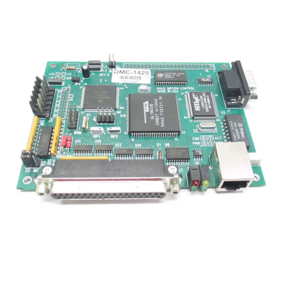
Chapter 2 Getting Started The DMC-141X Motion Controller Figure 2.1 – Outline of the DMC-1415/DMC-1425 Figure 2.2 – Outline of the DMC-1416 DMC-14x5/6 Chapter 2 Getting Started Artisan Technology Group - Quality Instrumentation ... Guaranteed | (888) 88-SOURCE | www.artisantg.com... -
Page 17: Elements You Need
DMC-141X Flash EEPROM 10Base-T Ethernet connection Motorola 68331 microprocessor 37 Pin-D connection for controller signal break- GL-1800 custom gate array 15 Pin-D connection for controller main encoder breakout (DMC-1416) Reset switch 6 Pin power connector for +5V, +12V and –12V input (DMC-1415/DMC-1425) 5 Pin connector for 20 –... -
Page 18: Installing The Dmc-14Xx Controller
For the DMC-1416, the internal amplifier is a 20V to 60V PWM amplifier in either a brush or brushless configuration, so only a brush or brushless DC servo motor may be used. The WSDK software is highly recommended for first time users of the DMC-14XX. It provides step- by-step instructions for system connection, tuning and analysis. -
Page 19: Step 2. Configuring Jumpers On The Dmc-14Xx
available on the DMC-1425. In standard servo operation, the DMC-1415 has one DAC for the single axis. Issuing the BA command will enable the second DAC for commutation. Further instruction for sinusoidal commutation connections are discussed in Step 6. Stepper Motor Operation: To configure the DMC-141X for stepper motor operation, the controller requires that the command, MT, be given and jumpers placed to designate stepper motor. -
Page 20: Step 3. Connecting Dc Power And The Serial Cable To The Dmc-14Xx
JP 3 JP 3 Setting for analog m otor com mand Setting for step/direction output Figure 2.3 - Jumper settings for motor command output Setting the Baud Rate on the DMC-14XX The jumpers labeled “96” and “12” at JP1 allows the user to select the serial communication baud rate. The baud rate can be set using the following table: SWITCH SETTINGS BAUD RATE... -
Page 21: Step 4. Installing The Communications Software
4. Applying power will turn on the green LED power indicator. Step 4. Installing the Communications Software After applying power to the computer, you should install the Galil software that enables communication between the controller and PC. The CD-ROM used for the following installations is Version 11/01. - Page 22 Using Galil Software for Windows 3.x, 95 and 98 SE In order for the windows software to communicate with a Galil controller, the controller must be registered in the Windows Registry. To register a controller, you must specify the model of the controller, the communication parameters, and other information.
- Page 23 Select the button that says “New Controller” under the “Non-PnP Tools” and then select DMC-1415, DMC-1416 or DMC-1425 from the pull down menu. Make sure to select “Serial” as the “Connection Type”. The next step is to select the Comm Port being used on the PC and the Comm Speed for data transfer. Hardware handshaking will be selected by default.
- Page 24 Using Non-Galil Communication Software The DMC-14XX serial port is configured as DATASET. Your computer or terminal must be configured as a DATATERM for full duplex, no parity, 8 data bits, one start bit and one stop bit. Check to insure that the baud rate switches have been set to the desired baud rate as described above. Your computer needs to be configured as a "dumb"...
- Page 25 communicate it over Ethernet. Follow the steps above for registering an Ethernet controller but do not click the ASSIGN IP ADDRESS button. Just click OK once the IP address has been entered in the text box, and the controller will be entered into the Galil registry. Connect to the controller through the Terminal utility.
- Page 26 slows the response time. For more information, contact Galil. Once all the Ethernet parameters are entered, select “Assign IP Address”. The software will search for controllers that do not have IP addresses. Once the controller has been found and the IP address is assigned, select “Finish”, and the controller will be entered in the Galil Registry.
-
Page 27: Step 6. Set-Up Axis For Sinusoidal Commutation (Dmc-1415 Only)
straight through cable must be used. Hubs perform the signal crossing function of a null-modem cable. If the wrong cable is used, communication with the controller will not be possible. Note: If an Ethernet controller is connected in a LAN, make sure the assigned IP address is allowed. Also, Galil strongly recommends the IP address selected cannot be accessed across the Gateway. - Page 28 the resistor. Only if the voltage is zero, proceed to connect the two ground signals directly. The amplifier enable signal is used by the controller to disable the motor. This signal is labeled AMPEN on the ICM-1460 and should be connected to the enable signal on the amplifier.
-
Page 29: Step 8A. Connect Standard Servo Motor
the encoder failed, replace the encoder. If you cannot observe the encoder signals, try a different encoder. 3. There is a hardware failure in the controller - connect the same encoder to a different axis. If the problem disappears, you probably have a hardware failure. Consult the factory for help. - Page 30 To limit the maximum voltage signal to your amplifier, the DMC-141X controller has a torque limit command, TL. This command sets the maximum voltage output of the controller and can be used to avoid excessive torque or speed when initially setting up a servo system.
- Page 31 If the motor moves in the required direction but stops short of the target, it is most likely due to insufficient torque output from the motor command signal ACMD. This can be alleviated by reducing system friction on the motors. The instruction: TT <CR>...
-
Page 32: Step 8B. Connect Brushless Motor For Sinusoidal Commutation (Dmc- 1415 Only)
IC M -1 4 6 0 D e sc rip tio n C o n n e ctio n C h a n n e l A + M A + C h a n n e l B + M B + C h a n n e l A - M A -... - Page 33 It is not necessary to be concerned with cross-wiring the 1 and 2 signals. If this wiring is incorrect, the setup procedure will alert the user (Step D). Step C. Specify the Size of the Magnetic Cycle. Use the command, BM, to specify the size of the brushless motors magnetic cycle in encoder counts.
- Page 34 When an axis has been defined as sinusoidally commutated, the controller must have an estimate for commutation phase. When hall sensors are used, the controller automatically estimates this value upon reset of the controller. If no hall sensors are used, the controller will not be able to make this estimate and the commutation phase must be set before enabling the motor.
-
Page 35: Step 8C. Connect Step Motors
that occurs, the controller computes the commutation phase and sets it. For example, to initialize the motor upon power or reset, the following commands may be given: SH <CR> Enable motor BC <CR> Enable the brushless calibration command PR 50000 <CR> Command a relative position movement BG <CR>... -
Page 36: Step 9. Tune The Servo System
Step A. Disconnect controller power Unplug the 5-pin power connector (J5) from the front of the DMC-1416. This will power down the controller so that the motor may be connected. Step B. Connect DC brush or brushless motor If using the DMC-1416 with the brush amplifier, connect the motor leads to the corresponding screw terminals on the 5-pin power connector labeled M+ and M-. -
Page 37: Design Examples
Next you need to increase the value of KP gradually (maximum allowed is 1023). You can monitor the improvement in the response with the Tell Error instruction KP 10 <CR> Proportion gain TE <CR> Tell error As the proportional gain is increased, the error decreases. Again, the system may vibrate if the gain is too high. -
Page 38: Example 4 - Absolute Position
Tell position which returns the position of the main encoder. The position error, which is the difference between the commanded position and the actual position can be interrogated by the instructions Tell error Example 4 - Absolute Position Objective: Command motion by specifying the absolute position. Instruction Interpretation DP 0... -
Page 39: Example 7 - Interrogation
Example 7 - Interrogation The values of the parameters may be interrogated using a ?. For example, the instruction KP ? Return gain The same procedure applies to other parameters such as KI, KD, FA, etc. Example 8 - Operation in the Buffer Mode The instructions may be buffered before execution as shown below. -
Page 40: Example 11- Motion Programs With Trippoints
V1=V1+1000 Increase the value of V1 JP #Loop,V1<10001 Repeat if V1<10001 After the above program is entered, quit the Editor Mode, <cntrl>Q. To start the motion, command: XQ #A Execute Program #A Example 11- Motion Programs with Trippoints The motion programs may include trippoints as shown below. Instruction Interpretation Label... -
Page 41: Example 13 - Control Variables And Offset
This program moves the motor to an initial position of 1000 and returns it to zero on increments of half the distance. Note, _TP is an internal variable which returns the value of the position. Internal variables may be created by preceding a DMC-141X instruction with an underscore, _. Example 13 - Control Variables and Offset Objective: Illustrate the use of variables in iterative loops and use of multiple instructions on one line. -
Page 42: Chapter 3 Connecting Hardware
Chapter 3 Connecting Hardware Overview The DMC-1415 and DMC-1416 provide digital inputs for forward limit, reverse limit, home and abort signals. The controller also has 7 uncommitted, TTL inputs (for general use), 3 TTL outputs and 2 analog inputs (12-bit). The DMC-1425 provides digital inputs for X and Y forward limit, X and Y reverse limit, X and Y home input and abort input. -
Page 43: Home Switch Input
Home Switch Input Homing inputs are designed to provide mechanical reference points for a motion control application. A transition in the state of a Home input alerts the controller that a particular reference point has been reached by a moving part in the motion control system. A reference point can be a point in space or an encoder index pulse. -
Page 44: Uncommitted Digital Inputs
longer under servo control. If the Off-On-Error function is disabled, the motor will decelerate to a stop as fast as mechanically possible and the motor will remain in a servo state. All motion programs that are currently running are terminated when a transition in the Abort input is detected. -
Page 45: Ttl Inputs
DMC-14XX ICM-1460 Connection to +5V or +12V made through jumper at JP4. Removing the jumper allows the user to connect a load (e.g. optoisolator or relay) between AMPEN and their own +12V supply at the desired voltage level (up to 24V). - Page 46 Reference. The value of the outputs can be checked with the operand _OP and the function @OUT[] (see Chapter 7, Mathematical Functions and Expressions). The output compare signal is TTL and is available on the ICM-1460 as CMP. Output compare is controlled by the position of any of the main encoders on the controller.
- Page 47 THIS PAGE LEFT BLANK INTENTIONALLY Chapter 3 Connecting Hardware DMC-14x5/6 Artisan Technology Group - Quality Instrumentation ... Guaranteed | (888) 88-SOURCE | www.artisantg.com...
-
Page 48: Chapter 4 Communication
Chapter 4 Communication Introduction The DMC-14XX has one RS232 port and one Ethernet port. The RS-232 port is the data set. The Ethernet port is a 10Base-T link. The RS-232 is a standard serial link with communication baud rates up to 19.2kbaud. RS232 Port The DMC-14XX has a single RS232 connection for sending and receiving commands from a PC or other terminal. -
Page 49: Ethernet Configuration
RTS line goes high for inhibit. This handshake procedure ensures proper communication especially at higher baud rates. Ethernet Configuration Communication Protocols The Ethernet is a local area network through which information is transferred in units known as packets. Communication protocols are necessary to dictate how these packets are sent and received. The DMC-14XX supports two industry standard protocols, TCP/IP and UDP/IP. - Page 50 Ethernet Parameters Tab in Win 95/98 Ethernet Parameters Window in Win 98SE/2000/ME/NT 4/XP The second method for setting an IP address is to send the IA command through the DMC-14XX main RS-232 port. The IP address you want to assign may be entered as a 4 byte number delimited by commas (industry standard uses periods) or a signed 32 bit number (Ex.
-
Page 51: Communicating With Multiple Devices
NOTE: Galil strongly recommends that the IP address selected is not one that can be accessed across the Gateway. The Gateway is an application that controls communication between an internal network and the outside world. The third level of Ethernet addressing is the UDP or TCP port number. The Galil controller does not require a specific port number. -
Page 52: Multicasting
The DMC-14XX provides three levels of Modbus communication. The first level allows the user to create a raw packet and receive raw data. It uses the MBh command with a function code of –1. The format of the command is MBh = -1,len,array[] where len is the number of bytes... -
Page 53: Data Record
Data Record The DMC-14x5 provide a block of status information with the use of a single command, QR. This command, along with the QZ command can be very useful for accessing complete controller status. The QR command will return 4 bytes of header information and specific blocks of information as specified by the command arguments: QR ABCDEFGHST Each argument corresponds to a block of information according to the Data Record Map below. -
Page 54: Explanation Of Status Information And Axis Switch Information
distance traveled in coordinated move for S plane S block segment count of coordinated move for T plane T block coordinated move status for T plane T block distance traveled in coordinated move for T plane T block a axis status A block a axis switches A block... -
Page 55: Notes Regarding Velocity And Torque Information
General Status Information (1 Byte) BIT 7 BIT 2 BIT 1 BIT 0 Program Waiting for Trace On Echo On Running input from IN command Axis Switch Information (1 Byte) BIT 7 BIT 6 BIT 5 BIT 4 BIT 3 BIT 2 BIT 1 BIT 0... -
Page 56: Qz Command
QZ Command The QZ command can be very useful when using the QR command, since it provides information about the controller and the data record. The QZ command returns the following 4 bytes of information. BYTE # INFORMATION Number of axes present number of bytes in general block of data record number of bytes in coordinate plane block of data record Number of Bytes in each axis block of data record... -
Page 57: Galil Software Tools And Libraries
When hardware handshaking is used, characters which are generated by the controller are placed in a single character buffer before they are sent out of the controller. When this buffer becomes full, the controller must either stop executing commands or ignore additional characters generated for output. The command CW,1 causes the controller to ignore all output from the controller while the FIFO is full. -
Page 58: Chapter 5 Command Basics
Chapter 5 Command Basics Introduction The DMC-14XX provides over 100 commands for specifying motion and machine parameters. Commands are included to initiate action, interrogate status and configure the digital filter. These commands can be sent in ASCII or binary. In ASCII, the DMC-14XX instruction set is BASIC-like and easy to use. Instructions consist of two uppercase letters that correspond phonetically with the appropriate function. -
Page 59: Coordinated Motion With More Than 1 Axis
To view the current values for each command, type the command followed by a ? for each axis requested. This is interrogation. Not all commands can be interrogated. Refer to the Command Reference to determine whether or not a command can be interrogated. PR 1000 Specify X only as 1000 PR ,2000... -
Page 60: Binary Command Format
Binary Command Format All binary commands have a 4 byte header and are followed by data fields. The 4 bytes are specified in hexadecimal format. Header Format: Byte 1 specifies the command number between 80 and FF. The complete binary command number table is listed below. -
Page 61: Binary Command Table
Binary Command Table Command Command Command reserved reserved reserved reserved reserved reserved reserved reserved reserved LE, VE reserved reserved reserved reserved reserved reserved reserved reserved reserved reserved reserved reserved reserved reserved reserved reserved reserved reserved reserved reserved reserved reserved reserved reserved reserved reserved... -
Page 62: Controller Response To Data
Controller Response to DATA The DMC-14XX returns a : for valid commands. The DMC-14XX returns a ? for invalid commands. For example, if the command BG is sent in lower case, the DMC-14XX will return a ?. :bg <enter> invalid command, lower case DMC-14XX returns a ? When the controller receives an invalid command the user can request the error code. -
Page 63: Interrogating Current Commanded Values
0000000000 Controllers Response TP XY <enter> Tell position X and Y 0000000000,0000000000 Controllers Response Interrogating Current Commanded Values. Most commands can be interrogated by using a question mark (?) as the axis specifier. Type the command followed by a ? for each axis requested. PR ?,? Request X,Y values PR ,? -
Page 64: Chapter 6 Programming Motion
Chapter 6 Programming Motion Overview The DMC-14XX provides several modes of motion, including independent positioning and jogging, coordinated motion, electronic cam motion, and electronic gearing. Each one of these modes is discussed in the following sections. The DMC-1415 and DMC-1416 are single axis controllers and use X-axis motion only. The DMC- 1425 is a two axis controller and uses both X and Y. -
Page 65: Independent Axis Positioning
Third axis must remain tangent to 2-D motion path, Coordinated motion with tangent axis such as knife cutting. specified VS,VA,VD Electronic gearing where slave axes are scaled to Electronic Gearing master axis which can move in both directions. GM (if gantry) Master/slave where slave axes must follow a Electronic Gearing master such as conveyer speed. -
Page 66: Command Summary - Independent Axis
The Begin (BG) command can be issued for all axes either simultaneously or independently. X or Y axis specifiers are required to select the axes for motion. When no axes are specified, this causes motion to begin on all axes. The speed (SP) and the acceleration (AC) can be changed at any time during motion, however, the deceleration (DC) and position (PR or PA) cannot be changed until motion is complete. - Page 67 Example - Multiple Move Sequence Required Motion Profiles: X-Axis 2000 counts Position 15000 count/sec Speed 500000 counts/sec 2 Acceleration Y-Axis 100 counts Position 5000 count/sec Speed 500000 counts/sec 2 Acceleration This example will specify a relative position movement on X and Y axes. The movement on each axis will be separated by 40 msec.
-
Page 68: Independent Jogging
Independent Jogging The jog mode of motion is very flexible because speed, direction and acceleration can be changed during motion. The user specifies the jog speed (JG), acceleration (AC), and the deceleration (DC) rate for each axis. The direction of motion is specified by the sign of the JG parameters. When the begin command is given (BG), the motor accelerates up to speed and continues to jog at that speed until a new speed or stop (ST) command is issued. -
Page 69: Linear Interpolation Mode
BG X Begin X motion AS X Wait until X is at speed BG Y Begin Y motion Linear Interpolation Mode The DMC-14XX provides a linear interpolation mode for 2 axes. In linear interpolation mode, motion between the axes is coordinated to maintain the prescribed vector speed, acceleration, and deceleration along the specified path. - Page 70 VT is used to set the smoothing constant for coordinated moves. The command AV n is the ‘After Vector’ trippoint, which halts program execution until the vector distance of n has been reached. An Example of Linear Interpolation Motion: Instruction Interpretation #LMOVE Label...
-
Page 71: Command Summary - Linear Interpolation
Changing Feedrate: The command VR n allows the feedrate, VS, to be scaled between 0 and 10 with a resolution of .0001. This command takes effect immediately and causes VS to be scaled. VR also applies when the vector speed is specified with the ‘<’ operator. This is a useful feature for feedrate override. VR does not ratio the accelerations. -
Page 72: Example - Linear Move
Example - Linear Move Make a coordinated linear move in the XY plane. Move to coordinates 40000,30000 counts at a vector speed of 100000 counts/sec and vector acceleration of 1000000 counts/sec 2 . Instruction Interpretation LM XY Specify axes for linear interpolation LI40000,30000 Specify XY distances Specify end move... - Page 73 30000 27000 POSITION Y 3000 4000 36000 40000 POSITION X FEEDRATE TIME (sec) VELOCITY X-AXIS TIME (sec) VELOCITY Y-AXIS TIME (sec) Figure 6.2 - Linear Interpolation Chapter 6 Programming Motion DMC-14x5/6 Artisan Technology Group - Quality Instrumentation ... Guaranteed | (888) 88-SOURCE | www.artisantg.com...
-
Page 74: Example - Multiple Moves
Example - Multiple Moves This example makes a coordinated linear move in the XY plane. The Arrays VX and VY are used to store 750 incremental distances which are filled by the program #LOAD. Instruction Interpretation #LOAD Load Program DM VX [750],VY [750] Define Array COUNT=0 Initialize Counter... -
Page 75: Additional Commands
position to be zero for all movements in a sequence. Note: This ‘local’ definition of zero does not affect the absolute coordinate system or subsequent coordinated motion sequences. The command, VP x,y specifies the coordinates of the end points of the vector movement with respect θ,δ... -
Page 76: Command Summary - Coordinated Motion Sequence
vector speed is specified with the ‘<’ operator. This is a useful feature for feedrate override. VR does not ratio the accelerations. For example, VR .5 results in the specification VS 2000 act as VS 1000. Compensating for Differences in Encoder Resolution: By default, the DMC-14XX uses a scale factor of 1:1 for the encoder resolution when used in vector mode. -
Page 77: Electronic Gearing
Example: Traverse the path shown in Fig. 6.3. Feedrate is 20000 counts/sec. Plane of motion is XY Instruction Interpretation VM XY Specify motion plane VS 20000 Specify vector speed VA 1000000 Specify vector acceleration VD 1000000 Specify vector deceleration VP -4000,0 Segment AB CR 1500,270,-180 Segment BC... -
Page 78: Command Summary - Electronic Gearing
X or Y axis. The masters may rotate in both directions and the geared axes will follow at the specified gear ratio. The gear ratio may be different for each axis and changed during motion. The command GA specifies the master axes for the DMC-1425. The GA command is unnecessary for the DMC-1415 or DMC-1416, as the auxiliary encoder is automatically used. -
Page 79: Electronic Cam
Example - Gantry Mode In applications where both the master and the follower are controlled by the DMC-1425 controller, it may be desired to synchronize the follower with the commanded position of the master, rather than the actual position. This eliminates the possibility of an oscillation on the master passing the oscillation on to the slave. - Page 80 In this example x axis will be the master. Thus we specify EAX Step 2. Specify the master cycle and the change in the slave axes. In the electronic cam mode, the position of the master is always expressed within one cycle. In this example, the position of x is always expressed in the range between 0 and 6000.
- Page 81 where n indicates the order of the point. The value, n, starts at zero and may go up to 256. The parameters x,y indicate the corresponding slave position. For this example, the table may be specified by ET[0]=0 ET[0]=0 ET[1]=,3000 DMC-1425 ET[1]=3000 DMC-1415/1416...
- Page 82 3000 2250 1500 2000 4000 6000 Master X Figure 6.4 - Electronic Cam Example This disengages the slave axis at a specified master position. If the parameter is outside the master cycle, the stopping is instantaneous. To illustrate the complete process, consider the cam relationship described by the equation: Y = 0.5 * X + 100 sin (0.18 * X) where X is the master, with a cycle of 2000 counts.
- Page 83 EP 20,0 Master position increments N = 0 Index #LOOP Loop to construct table from equation P = N∗3.6 Note 3.6 = 0.18∗20 S = @SIN [P] * 100 Define sine position Y = N * 10+S Define slave position ET [N] =, Y Define table N = N+1...
-
Page 84: Contour Mode
ET[7]=,120 8th point in the ECAM table ET[8]=,60 9th point in the ECAM table ET[9]=,20 10th point in the ECAM table ET[10]=,0 Starting point for next cycle EB 1 Enable ECAM mode JGX=4000 Set Z to jog at 4000 EG ,0 Engage both X and Y when Master = 0 Begin jog on Z axis #LOOP;JP#LOOP,V1=0... -
Page 85: Additional Commands
The programmed commands to specify the above example are: Instruction Description Label Specifies X axis for contour mode DT 2 Specifies first time interval, 2 CD 48;WC Specifies first position increment DT 3 Specifies second time interval, 2 CD 240;WC Specifies second position increment DT 4 Specifies the third time interval, 2... -
Page 86: Operand Summary - Contour Mode
Specifies which axes for contouring mode. Any non-contouring axes may be operated in CM XY other modes. CD x,y Specifies position increment over time interval. Range is +/-32,000. Zero ends contour mode. DT n Specifies time interval 2 msec for position increment, where n is an integer between 1 and 8. - Page 87 ACCELERATION VELOCITY POSITION Figure 6.6 - Velocity Profile with Sinusoidal Acceleration The DMC-14XX can compute trigonometric functions. However, the argument must be expressed in degrees. Using our example, the equation for X is written as: X = 50T - 955 sin 3T A complete program to generate the contour movement in this example is given below.
- Page 88 Contour Mode Example Instruction Interpretation #POINTS Program defines X points DM POS[16] Allocate memory DM DIF[15] Set initial conditions, C is index T is time in ms V1=50*T V2=3*T Argument in degrees V3=-955*@SIN[V2]+V1 Compute position V4=@INT[V3] Integer value of V3 POS[C]=V4 Store in array POS T=T+8...
-
Page 89: Stepper Motor Operation
Teach (Record and Play-Back) Several applications require teaching the machine a motion trajectory. Teaching can be accomplished using the DMC-14XX automatic array capture feature to capture position data. The captured data may then be played back in the contour mode. The following array commands are used: DM C[n] Dimension array RA C[]... -
Page 90: Specifying Stepper Motor Operation
Specifying Stepper Motor Operation In order to command stepper motor operation, the appropriate stepper mode jumpers must be installed. See chapter 2 for this installation. Stepper motor operation is specified by the command MT. The argument for MT is as follows: 2 specifies a stepper motor with active low step output pulses -2 specifies a stepper motor with active high step output pulses 2.5 specifies a stepper motor with active low step output pulses and reversed direction... -
Page 91: Using An Encoder With Stepper Motors
Stepper Smoothing Filter Output Motion Profiler Output Buffer (Adds a Delay) (To Stepper Driver) Reference Position (RP) Step Count Register (TD) Motion Complete Trippoint When used in stepper mode, the MC command will hold up execution of the proceeding commands until the controller has generated the same number of steps out of the step count register as specified in the commanded position. -
Page 92: Aux Encoder/ Dual Loop (Dmc-1415 And Dmc-1416 Only)
Aux Encoder/ Dual Loop (DMC-1415 and DMC-1416 only) The DMC-141X provides an interface for a second encoder except when the controller is configured for stepper motor operation. When used, the second encoder is typically mounted on the motor or the load, but may be mounted in any position. - Page 93 Continuous Dual Loop - Example Connect the load encoder to the main encoder port and connect the motor encoder to the dual encoder port. The dual loop method splits the filter function between the two encoders. It applies the KP (proportional) and KI (integral) terms to the position error, based on the load encoder, and applies the KD (derivative) term to the motor encoder.
-
Page 94: Motion Smoothing
Motion Smoothing The DMC-14XX controller allows the smoothing of the velocity profile to reduce mechanical vibrations in the system. Trapezoidal velocity profiles have acceleration rates which change abruptly from zero to maximum value. The discontinuous acceleration results in jerk which causes vibration. The smoothing of the acceleration profile leads to a continuous acceleration profile and reduces the mechanical shock and vibration. -
Page 95: Using The Ks Command (Step Motor Smoothing)
Figure 6.7 – Trapezoidal velocity and smooth velocity profiles Using the KS Command (Step Motor Smoothing) When operating with step motors, motion smoothing can be accomplished with the command, KS. The KS command smoothes the frequency of step motor pulses. Similar to the commands IT and VT this produces a smooth velocity profile. -
Page 96: Homing
Homing The Find Edge (FE) and Home (HM) instructions may be used to home the motor to a mechanical reference. This reference is connected to the Home input line. The HM command initializes the motor to the encoder index pulse in addition to the Home input. The configure command (CN) is used to define the polarity of the home input. - Page 97 The 4 different motion possibilities for the home sequence are shown in the following table. Direction of Motion Switch Type CN Setting Initial _HMX state Stage 1 Stage 2 Stage 3 Normally Open CN,-1 Reverse Forward Forward Normally Open CN,1 Forward Reverse Forward...
- Page 98 HOME SWITCH _HMX=0 _HMX=1 POSITION VELOCITY MOTION BEGINS IN FORWARD DIRECTION POSITION VELOCITY MOTION CHANGES DIRECTION POSITION VELOCITY MOTION IN FORWARD DIRECTION TOWARD INDEX POSITION INDEX PULSES POSITION Figure 6.8 – Homing Sequence for Normally Closed Switch and CN,-1 Example: Find Edge #EDGE Label AC 2000000...
-
Page 99: High Speed Position Capture
Find edge command Begin motion After complete MG "FOUND HOME" Send message DP 0 Define position as 0 High Speed Position Capture Often it is desirable to capture the position precisely for registration applications. The DMC-141X provides a position latch feature. This feature allows the position to be captured in less than 1 μsec of the external low or high input signal. -
Page 100: Chapter 7 Application Programming
Chapter 7 Application Programming Overview The DMC-14XX provides a powerful programming language that allows users to customize the controller for their particular application. Programs can be downloaded into the DMC-14XX memory freeing the host computer for other tasks. However, the host computer can send commands to the controller at any time, even while a program is being executed. -
Page 101: Edit Mode Commands
Edit Mode Commands <RETURN> Typing the return key causes the current line of entered instructions to be saved. The editor will automatically advance to the next line. Thus, hitting a series of <RETURN> will cause the editor to advance a series of lines. Note, changes on a program line will not be saved unless a <return> is given. <cntrl>P The <cntrl>P command moves the editor to the previous line. -
Page 102: Special Labels
The maximum number of labels, which may be defined, is 126. Valid labels #BEGIN #SQUARE #begin1 Invalid labels #1Square #123 A Simple Example Program: Instruction Interpretation #START Beginning of the Program PR 10000,20000 Specify relative distances on X and Y axes BG XY Begin Motion Wait for motion complete... -
Page 103: Commenting Programs
Commenting Programs Using the command, NO The DMC-14XX provides a command, NO, for commenting programs. This command allows the user to include up to 78 characters on a single line after the NO command and can be used to include comments from the programmer as in the following example: #PATH NO 2-D CIRCULAR PATH... -
Page 104: Executing Programs - Multitasking
REM HALF CIRCLE MOTION VP 0,3000 REM TOP LINE CR 1500,90,-180 REM HALF CIRCLE MOTION REM END VECTOR SEQUENCE REM BEGIN SEQUENCE MOTION REM END OF PROGRAM The REM statements will be removed when the program is downloaded to the controller. Executing Programs - Multitasking The DMC-14XX can run up to two independent programs simultaneously. -
Page 105: Debugging Programs
Begin motion After motion done WT 10 Wait 10 msec JP #LOOP2,@IN[2]=1 Repeat motion unless Input 2 is low Halt all tasks The program above is executed with the instruction XQ #TASK2,0 which designates TASK2 as the main thread (i.e. Thread 0). #TASK1 is executed within TASK2. Debugging Programs The DMC-14XX provides commands and operands which are useful in debugging application programs. - Page 106 To list the contents of the variable space, use the interrogation command LV (List Variables). To list the contents of array space, use the interrogation command LA (List Arrays). To list the contents of the Program space, use the interrogation command LS (List). To list the application program labels only, use the interrogation command LL (List Labels).
-
Page 107: Program Flow Commands
Program Flow Commands The DMC-14XX provides instructions to control program flow. The DMC-14XX program sequencer normally executes program instructions sequentially. The program flow can be altered with the use of event triggers, trippoints, and conditional jump statements. Event Triggers & Trippoints To function independently from the host computer, the DMC-14XX can be programmed to make decisions based on the occurrence of an event. - Page 108 DMC-14XX Event Triggers Command Function AM X Y or S Halts program execution until motion is complete on the specified axes or motion sequence(s). AM with no parameter tests for motion complete on all axes. This command is useful for separating motion sequences in a program.
-
Page 109: Event Trigger Examples
Event Trigger Examples: Event Trigger - Multiple Move Sequence The AM trippoint is used to separate the two PR moves. If AM is not used, the controller returns a ? for the second PR command because a new PR cannot be given until motion is complete. Instruction Interpretation #TWOMOVE... - Page 110 Event Trigger - Start Motion on Input This example waits for input 1 to go low and then starts motion. Note: The AI command actually halts execution of the program until the input occurs. If you do not want to halt the program sequences, you can use the Input Interrupt function (II) or use a conditional jump on an input, such as JP #GO,@IN[1] = 0.
-
Page 111: Conditional Jumps
Event Trigger - Multiple Move with Wait This example makes multiple relative distance moves by waiting for each to be complete before executing new moves. Instruction Interpretation #MOVES Label PR 12000 Distance SP 20000 Speed AC 100000 Acceleration Start Motion AD 10000 Wait a distance of 10,000 counts SP 5000... - Page 112 JP destination, logical condition Jump to location if logical condition is satisfied The destination is a program line number or label where the program sequencer will jump if the specified condition is satisfied. Note that the line number of the first line of program memory is 0. The comma designates "IF".
-
Page 113: Using If, Else, And Endif Commands
This statement will cause the program to jump to the label #TEST under two conditions; 1. If V1 is less than V2 AND V3 is less than V4. 2. If V5 is less than V6. Using the JP Command: If the condition for the JP command is satisfied, the controller branches to the specified label or line number and continues executing commands from this point. - Page 114 Note: An ENDIF command must always be executed for every IF command that has been executed. It is recommended that the user not include jump commands inside IF conditional statements since this causes re-direction of command execution. In this case, the command interpreter may not execute an ENDIF command.
-
Page 115: Subroutines
JP#WAIT,(@IN[1]=0) | (@IN[2]=0) Loop until both input 1 and input 2 are not active End Input Interrupt Routine without restoring trippoints Subroutines A subroutine is a group of instructions beginning with a label and ending with an end command (EN). Subroutines are called from the main program with the jump subroutine instruction JS, followed by a label or line number, and conditional statement. -
Page 116: Automatic Subroutines For Monitoring Conditions
Automatic Subroutines for Monitoring Conditions Often it is desirable to monitor certain conditions continuously without tying up the host or DMC- 14XX program sequences. The DMC-14XX can monitor several important conditions in the background. These conditions include checking for the occurrence of a limit switch, a defined input, position error, or a command error. - Page 117 Example - Position Error Instruction Interpretation Edit Mode 000 #LOOP Dummy Program 001 JP #LOOP;EN Loop 002 #POSERR Position Error Routine 003 V1=_TEX Read Position Error 004 MG "EXCESS POSITION ERROR" Print Message 005 MG "ERROR=",V1= Print Error 006 RE Return from Error <control>...
- Page 118 This simple program will issue the message “X fell short” if the X axis does not reach the commanded position within 1 second of the end of the profiled move. Example - Command Error Instruction Interpretation #BEGIN Begin main program IN "ENTER SPEED", SPEED Prompt for speed JG SPEED;BGX;...
-
Page 119: Mathematical And Functional Expressions
Begin thread 1 N=-1 Create new variable KP N Set KP to value of N, an invalid value Issue invalid command End of thread 1 #CMDERR Begin command error subroutine IF _TC=6 If error is out of range (KP -1) Set N to a valid number XQ _ED2,_ED1,1 Retry KP N command... -
Page 120: Bit-Wise Operators
& Logical And (Bit-wise) Logical Or (On some computers, a solid vertical line appears as a broken line) Parenthesis The numeric range for addition, subtraction and multiplication operations is +/-2,147,483,647.9999. The precision for division is 1/65,000. Mathematical operations are executed from left to right. Calculations within parentheses have precedence. -
Page 121: Functions
This program will accept a string input of up to 6 characters, parse each character, and then display each character. Notice also that the values used for masking are represented in hexadecimal (as denoted by the preceding ‘$’). For more information, see section Sending Messages. To illustrate further, if the user types in the string “TESTME”... -
Page 122: Programmable Variables
Example: PR POSX Assigns variable POSX to PR command JG RPMY*70 Assigns variable RPMY multiplied by 70 to JG command. Programmable Variables The DMC-14XX allows the user to create up to 126 variables. Each variable is defined by a name which can be up to eight characters. -
Page 123: Operands
Displaying the value of variables at the terminal Variables may be sent to the screen using the format, variable=. For example, V1= , returns the value of the variable V1. Operands Operands allow motion or status parameters of the DMC-14XX to be incorporated into programmable variables and expressions. -
Page 124: Arrays
Arrays For storing and collecting numerical data, the DMC-14XX provides array space for 2000 elements. The arrays are one dimensional and up to 14 different arrays may be defined. Each array element has a numeric range of 4 bytes of integer (2 )followed by two bytes of fraction (+/-2,147,483,647.9999). -
Page 125: Automatic Data Capture Into Arrays
POS[COUNT]=_TPX Record position into array element POS[COUNT]= Report position COUNT=COUNT+1 Increment counter JP #LOOP,COUNT<10 Loop until 10 elements have been stored End Program The above example records 10 position values at a rate of one value per 10 msec. The values are stored in an array named POS. - Page 126 Data Types for Recording: Data type Description _DEX 2nd encoder position (dual encoder) _TPX Encoder position _TEX Position error _SHX Commanded position _RLX Latched position Inputs Output _TSX Switches (only bit 0-4 valid) _SCX Stop code _NOX Status bits _TTX Torque Note: X may be replaced by Y for capturing data on the other axis.
-
Page 127: Deallocating Array Space
Deallocating Array Space Array space may be deallocated using the DA command followed by the array name. DA*[0] deallocates all the arrays. Input of Data (Numeric and String) Input of Data The command, IN, is used to prompt the user to input numeric or string data. Using the IN command, the user may specify a message prompt by placing a message in quotations. -
Page 128: Output Of Data (Numeric And String)
WT100;CB1 Wait 100 msec, then turn off cutter JP #CUT Repeat process End program Inputting String Variables String variables with up to six characters may input using the specifier, {Sn} where n represents the number of string characters to be input. If n is not specified, six characters will be accepted. For example, IN "Enter X,Y or Z", V{S} specifies a string variable to be input. -
Page 129: Displaying Variables And Arrays
Example: JG 50000;BGX;ASX MG "The Speed is", _TVX {F5.1} {N} {EA} MG "counts/sec" {EA} When #A is executed, the above example will appear on the screen (on handle A) as: The speed is 50000 counts/sec Summary of Message Functions: Function Description "... - Page 130 Using the PF Command to Format Response from Interrogation Commands The command, PF, can change format of the values returned by theses interrogation commands: BL ? LE ? DE ? PA ? DP ? PR ? EM ? TN ? FL ? VE ? IP ?
-
Page 131: Formatting Variables And Array Elements
-9, 5, 0, 7 Response from Interrogation Command (Without Leading Zeros) Local Formatting of Response of Interrogation Commands The response of interrogation commands may be formatted locally. To format locally, use the command, {Fn.m} or {$n.m} on the same line as the interrogation command. The symbol F specifies that the response should be returned in decimal format and $ specifies hexadecimal. -
Page 132: Converting To User Units
0010.00 New format :V1={$4.2} Specify hex format $000A.00 Hex value :V1="ALPHA" Assign string "ALPHA" to V1 :V1={S4} Specify string format first 4 characters ALPH The local format is also used with the MG* command. Converting to User Units Variables and arithmetic operations make it easy to input data in desired user units such as inches or RPM. -
Page 133: Digital Inputs
OB 3, @IN [1]&@IN [2] Set Output 3 only if Input 1 and Input 2 are high. OB 2, COUNT [1] Set Output 2 if element 1 in the array COUNT is non-zero. The output port can be set by specifying an 3-bit word using the instruction OP (Output Port). This instruction allows a single command to define the state of the entire 3-bit output port, where 2 0 is output 1, 2 1 is output 2 and so on. -
Page 134: Input Interrupt Function
AI 1;BGX Begin after input 1 goes high AI -1;STX Stop after input 1 goes low AMX;JP #S After motion, repeat Input Interrupt Function The DMC-14XX provides an input interrupt function which causes the program to automatically execute the instructions following the #ININT label. This function is enabled using the II m,n,o,p command. -
Page 135: Example Applications
Example Applications Wire Cutter An operator activates a start switch. This causes a motor to advance the wire a distance of 10". When the motion stops, the controller generates an output signal which activates the cutter. Allowing 100 ms for the cutting completes the cycle. Suppose that the motor drives the wire by a roller with a 2"... -
Page 136: X-Y Table Controller
START PULSE I1 MOTOR VELOCITY OUTPUT PULSE output TIME INTERVALS move wait ready move Figure 7.1 - Motor Velocity and the Associated Input/Output signals X-Y Table Controller An X-Y system must cut the pattern shown in Fig. 7.2. The X-Y table moves the plate while digital output 1 raises and lowers the cutting tool. - Page 137 Instruction Interpretation Label Set all output bits low VM XY Circular interpolation for XY VP 160000,160000 Positions End Vector Motion VS 200000 Vector Speed VA 1544000 Vector Acceleration Start Motion When motion is complete Set output bit to lower cutting tool WT1000 Wait 1000msec for tool to be in cutting position CR 80000,270,-360...
- Page 138 Figure 7.2 - Motor Velocity and the Associated Input/Output signals DMC-14x5/6 Chapter 7 Application Programming Artisan Technology Group - Quality Instrumentation ... Guaranteed | (888) 88-SOURCE | www.artisantg.com...
- Page 139 THIS PAGE LEFT BLANK INTENTIONALLY Chapter 7 Application Programming DMC-14x5/6 Artisan Technology Group - Quality Instrumentation ... Guaranteed | (888) 88-SOURCE | www.artisantg.com...
-
Page 140: Chapter 8 Hardware & Software Protection
Chapter 8 Hardware & Software Protection Introduction The DMC-14XX provides several hardware and software features to check for error conditions and to inhibit the motor on error. These features help protect the system components from damage. WARNING: Machinery in motion can be dangerous! It is the responsibility of the user to design effective error handling and safety protection as part of the machine. -
Page 141: Input Protection Lines
Input Protection Lines Abort - A low input stops commanded motion instantly without a controlled deceleration. For any axis in which the Off-On-Error function is enabled, the amplifiers will be disabled. This could cause the motor to ‘coast’ to a stop. If the Off-On-Error function is not enabled, the motor will instantaneously stop and servo at the current position. -
Page 142: Off-On-Error
JG 2000,2000 BG XY Begin Execution of the above example will cause the motor to slew at the given jog speed until the forward position limit is reached. Motion will stop once the limit is hit. Off-On-Error The DMC-14XX controller has a built in function which can turn off the motors under certain error conditions. - Page 143 following to be automatically executed if any limit switch is activated. The RE command ends the subroutine and resumes the main program where it left off. The state of the forward and reverse limit switches may also be interrogated or used in a conditional statement.
-
Page 144: Chapter 9 Troubleshooting
Chapter 9 Troubleshooting Overview The following discussion may help you get your system running if a problem is encountered. Potential problems have been divided into groups as follows: Installation Communication Stability and Compensation Operation The various symptoms along with the cause and the remedy are described in the following tables. Installation Symptom Cause... -
Page 145: Communication
Communication Symptom Cause Remedy Using DMCWIN, DMCDOS, Improper settings, jumper Make sure that the baud rate DMCTERM or WSDK cannot configurations and/or cable type set in the software communicate with the controller corresponds to the baud rate over RS-232 set by the jumpers on the controller Make sure a straight-through RS-232 cable is used... -
Page 146: Chapter 10 Theory Of Operation
Chapter 10 Theory of Operation Overview The following discussion covers the operation of motion control systems. A typical motion control system consists of the elements shown in Fig 10.1. COMPUTER CONTROLLER DRIVER ENCODER MOTOR Figure 10.1 - Elements of Servo Systems The operation of such a system can be divided into three levels, as illustrated in Fig. - Page 147 The highest level of control is the motion program. This can be stored in the host computer or in the controller. This program describes the tasks in terms of the motors that need to be controlled, the distances and the speed. LEVEL MOTION PROGRAMMING...
-
Page 148: Operation Of Closed-Loop Systems
X VELOCITY Y VELOCITY X POSITION Y POSITION TIME Figure 10.3 - Velocity and Position Profiles Operation of Closed-Loop Systems To understand the operation of a servo system, we may compare it to a familiar closed-loop operation, adjusting the water temperature in the shower. One control objective is to keep the temperature at a comfortable level, say 90 degrees F. -
Page 149: System Modeling
The results may be worse if we turn the faucet too fast. The overreaction results in temperature oscillations. When the response of the system oscillates, we say that the system is unstable. Clearly, unstable responses are bad when we want a constant level. What causes the oscillations? The basic cause for the instability is a combination of delayed reaction and high gain. -
Page 150: Motor-Amplifier
Motor-Amplifier The motor amplifier may be configured in three modes: 1. Voltage Drive 2. Current Drive 3. Velocity Loop The operation and modeling in the three modes is as follows: Voltage Drive The amplifier is a voltage source with a gain of Kv [V/V]. The transfer function relating the input voltage, V, to the motor position, P, is K S ST where... - Page 151 where Kt and J are as defined previously. For example, a current amplifier with K a = 2 A/V with the motor described by the previous example will have the transfer function: P/V = 1000/s 2 [rad/V] If the motor is a DC brushless motor, it is driven by an amplifier that performs the commutation. The combined transfer function of motor amplifier combination is the same as that of a similar brush motor, as described by the previous equations.
-
Page 152: Encoder
VOLTAGE SOURCE +1)(ST CURRENT SOURCE VELOCITY LOOP Figure 10.6 - Mathematical model of the motor and amplifier in three operational modes Encoder The encoder generates N pulses per revolution. It outputs two signals, Channel A and B, which are in quadrature. -
Page 153: Dac
The DAC or D-to-A converter converts a 16-bit number to an analog voltage. The input range of the numbers is 65536 and the output voltage range is +/-10V or 20V. Therefore, the effective gain of the DAC is K= 20/65536 = 0.0003 [V/count] Digital Filter The digital filter has a transfer function of D(z) = [K(z-A)/z + Cz/(z-1)] and a sampling time of T. -
Page 154: System Analysis
System Analysis To analyze the system, we start with a block diagram model of the system elements. The analysis procedure is illustrated in terms of the following example. Consider a position control system with the DMC-14XX controller and the following parameters: K t = 0.1 Nm/A Torque constant... - Page 155 FILTER MOTOR 2000 Σ 50+0.980s 0.0003 S+2000 ENCODER Figure 10.7 - Mathematical model of the control system The open loop transfer function, A(s), is the product of all the elements in the loop. A = 390,000 (s+51)/[s 2 (s+2000)] To analyze the system stability, determine the crossover frequency, ω c at which A(j ω c ) equals one. This can be done by the Bode plot of A(j ω...
-
Page 156: System Design And Compensation
As long as PM is positive, the system is stable. However, for a well damped system, PM should be between 30 degrees and 45 degrees. The phase margin of 70 degrees given above indicated overdamped response. Next, we discuss the design of control systems. System Design and Compensation The closed-loop control system can be stabilized by a digital filter, which is preprogrammed in the DMC-14XX controller. - Page 157 Then the open loop transfer function, A(s), is A(s) = L(s) G(s) Now, determine the magnitude and phase of L(s) at the frequency ω c = 500. L(j500) = 3.17∗10 6 /[(j500) 2 (j500+2000)] This function has a magnitude of |L(j500)| = 0.00625 and a phase Arg[L(j500)] = -180°...
- Page 158 D = 4 ∗ KD ∗ T 4 ∗ KD = D/T Assuming a sampling period of T=1ms, the parameters of the digital filter are: KP = 20.6 KD = 68.6 The DMC-14XX can be programmed with the instruction: KP 20.6 KD 68.6 In a similar manner, other filters can be programmed.
- Page 159 THIS PAGE LEFT BLANK INTENTIONALLY Chapter 10 Theory of Operation DMC-14x5/6 Artisan Technology Group - Quality Instrumentation ... Guaranteed | (888) 88-SOURCE | www.artisantg.com...
-
Page 160: Appendices
Appendices Electrical Specifications Servo Control ACMD Amplifier Command: +/-10 Volts analog signal. Resolution 16-bit DAC or .0003 Volts. 3 mA maximum A+,A-,B+,B-,IDX+,IDX- Encoder and Auxiliary TTL compatible, but can accept up to +/-12 Volts. Quadrature phase on CHA,CHB. Can accept single- ended (A+,B+ only) or differential (A+,A-,B+,B-). -
Page 161: Performance Specifications
*The +12V DC-to-DC converter on the DMC-1416 is maxed out at 40mA. Do not attempt to draw any more current out of the +12V pins +5V : .5A available -12v : 100mA available Performance Specifications Minimum Servo Loop Update Time: Normal Firmware Fast Firmware 250 μsec... -
Page 162: Connectors For Dmc-14Xx
Stepper Motor Operation (MT 2,-2,2.5,-2.5) Trippoints in thread 2-8 Tell Velocity Interrogation Command (TV) Connectors for DMC-14XX J3 DMC-1415 General I/O; 37- PIN D-type (Female) 1 Reset 20 Error 2 Amp Enable 21 ACMD (also PWM when JP3 jumpered) 3 Output 3 22 Output 2 4 Output 1 23 Circular Compare... -
Page 163: J3 Dmc-1416 General I/O; 37- Pin D-Type
6 Y Encoder Index + (Input 7) 25 Home Y (Input 6) 7 Reverse Limit Y (Input 5) 26 Forward Limit Y (Input 4) 8 Input 3 (Y Encoder Index- 27 Input 2 (and Y latch) 9 Input 1 (and X latch) 28 Forward Limit X 10 + 5V 29 Reverse Limit X... -
Page 164: J4 Dmc-1416 Encoders; 15-Pin D-Type
15 MB- 34 IDX + 16 IDX- 35 Auxiliary A + 17 Auxiliary A - 36 Auxiliary B + 18 Auxiliary B - 37 Abort 19 NC If the controller is older than Rev C. These pins will have no connection. To add encoder signals in this case, contact Galil. -
Page 165: Pin-Out Description
Pin-Out Description OUTPUTS Analog Motor Command +/- 10 Volt range signal for driving amplifier. In servo mode, motor command output is updated at the controller sample rate. In the motor off mode, this output is held at the OF command level. Amp Enable Signal to disable and enable an amplifier. -
Page 166: Icm-1460 Interconnect Module
Reset input A low input resets the state of the processor to its power-on condition. The previously saved state of the controller, along with parameter values, and saved sequences are restored. Forward Limit Switch When active, inhibits motion in forward direction. Also causes execution of limit switch subroutine, #LIMSWI. - Page 167 RESET Reset ERROR/PULSE(Y) Error signal or Y Axis Pulse Output for Stepper OUT3 Output 3 OUT2 Output 2 OUT1 Output 1 CMP/ICOM Circular Compare / Input common for Opto option + 5 Volts Signal Ground IN7/INDY+ Input 7 (Y Axis Main Encoder Index + for DMC-1425) IN6/HOMY Input 6 (Y Axis Home input for DMC-1425) IN5/RLSY...
-
Page 168: Opto-Isolation Option For Icm-1460 (Rev F And Above)
7 The screw terminal for CMP can be configured as input/output common for opto-isolated I/O. Please see next section for detail. Opto-Isolation Option for ICM-1460 (rev F and above) The ICM-1460 module from Galil has an option for opto-isolated inputs and outputs. Any of the following pins can be chosen to be the input/output common: pin 1 (labeled as +12V), pin 2 (labeled as –12V) and pin 13 (labeled as CMP/ICOM). -
Page 169: 64 Extended I/O Of The Dmc-1415/1416/1425 Controller
Figure A-2 – Opto-isolated Outputs The signal “OUT[x]" is one of the isolated digital outputs where x stands for the digital output terminals. The OPTO-COMMON needs to be connected to an isolated power supply. The OUT[x] can be used to source current from the power supply. - Page 170 The least significant bit represents block 2 and the most significant bit represents block 9. The decimal value can be calculated by the following formula. n = n + 2*n + 4*n + 8*n +16* n +32* n +64* +128* n where n represents the block.
-
Page 171: Connector Description
Argument Blocks Bits Description General Outputs 17-32 Extended I/O 33-48 Extended I/O 49-64 Extended I/O 65-80 Extended I/O For example, if block 8 is configured as an output, the following command may be issued: OP 7,,,,7 This command will set bits 1,2,3 (block 0) and bits 65,66,67 (block 8) to 1. Bits 4 through 8 and bits 68 through 80 will be set to 0. - Page 172 J8 50-PIN IDC Signal Block Bit @IN[n], Bit No @OUT[n] DMC-14x5/6 Appendices Artisan Technology Group - Quality Instrumentation ... Guaranteed | (888) 88-SOURCE | www.artisantg.com...
-
Page 173: Iom-1964 Opto-Isolation Module For Extended I/O Controllers
IOM-1964 Opto-Isolation Module for Extended I/O Controllers Description: • Provides 64 optically isolated inputs and outputs, each rated for 2mA at up to 28 • Configurable as inputs or outputs in groups of eight bits • Provides 16 high power outputs capable of up to 500mA each •... -
Page 174: Overview
High Current Screw Terminals Buffer chips (16) IOM-1964 REV B GALIL MOTION CONTROL MADE IN USA FOR INPUTS: FOR OUTPUTS: RPX4 RPX2 RPX3 Banks 0 and 1 80 pin high Banks 2-7 are provide high density connector standard banks. power output capability. -
Page 175: Configuring Hardware Banks
Configuring Hardware Banks The extended I/O on the DMC-1415/1416/1425 and DB-14064 is configured using the CO command. The banks of buffers on the IOM-1964 are configured to match by inserting the appropriate IC’s and resistor packs. The layout of each of the I/O banks is identical. For example, here is the layout of bank 0: Resistor Pack for outputs... - Page 176 and U14, and so on. Also, the resistor pack RPx4 must be inserted into the bank to finish the input configuration. I/OC 1/8 RPx4 1/4 NEC2505 To DMC-14XX* I/O x = bank number 0-7 n = input number 17-80 DMC-14XX* GND Figure A-5 –...
-
Page 177: High Power Digital Outputs
Note that the current through the digital input should be kept below 3 mA in order to minimize the power dissipated in the resistor pack. This will help prevent circuit failures. The resistor pack RPx4 is standard 1.5k ohm that is suitable for power supply voltages up to 5.5 VDC. However, use of 24 VDC for example would require a higher resistance such as a 10k ohm resistor pack. -
Page 178: Standard Digital Outputs
The power outputs must be connected in a driving configuration as shown on the previous page. Here are the voltage outputs to expect after the Clear Bit and Set Bit commands are given: Output Command Result = GND Standard Digital Outputs The I/O banks 2-7 can be configured as optically isolated digital outputs, however these banks do not have the high power capacity as in banks 0-1. -
Page 179: Electrical Specifications
Output Command Result = GND The resistor pack RPx3 is removed to provide open collector outputs. The same calculations for maximum source current and low level voltage applies as in the above circuit. The maximum sink current is determined by the NEC2505, and is approximately 2mA. Open Collector To DMC-14XX +5V 1/4 NEC2505... -
Page 180: Relevant Dmc Commands
• Maximum sink current: 2mA Relevant DMC Commands CO n Configures the 64 bits of extended I/O in 8 banks of 8 bits each. n = n + 2*n + 4*n + 8*n + 16*n + 32*n + 64*n + 128*n where n is a 1 or 0, 1 for outputs and 0 for inputs. - Page 181 Appendices DMC-14x5/6 Artisan Technology Group - Quality Instrumentation ... Guaranteed | (888) 88-SOURCE | www.artisantg.com...
-
Page 182: Screw Terminal Listing
Screw Terminal Listing Rev A+B boards (orange) and Rev C boards (black) have the pinouts listed below REV A+B REV C LABEL DESCRIPTION BANK TERMINAL # TERMINAL # Ground 5V DC out Ground 5V DC out I/O80 I/O bit 80 I/O79 I/O bit 79 I/O78... - Page 183 I/O64 I/O bit 64 I/O63 I/O bit 63 I/O62 I/O bit 62 I/O61 I/O bit 61 I/O60 I/O bit 60 I/O59 I/O bit 59 I/O58 I/O bit 58 I/O57 I/O bit 57 OUTC57-64 Out common for I/O 57-64 I/OC57-64 I/O common for I/O 57-64 I/O56 I/O bit 56 I/O55...
- Page 184 I/O27 I/O bit 27 I/O26 I/O bit 26 I/O25 I/O bit 25 OUTC25-32 Out common for I/O 25-32 I/OC25-32 I/O common for I/O 25-32 OUTC25-32 Out common for I/O 25-32 I/OC25-32 I/O common for I/O 25-32 PWROUT32 Power output 32 PWROUT31 Power output 31 PWROUT30...
-
Page 185: Cb-50-80 Adapter Board
CB-50-80 Adapter Board The CB-50-80 adapter board can be used to convert the (2) 50 Pin Ribbon Cables from a DB-14064 to a CABLE-80. The CABLE-80 is used to connect to the IOM-1964. Connectors: JC8 and JC6: 50 Pin Male IDC J9: 80 Pin High Density Connector, AMP PART #3-178238-0 Appendices DMC-14x5/6... - Page 186 J9 (Continued) DMC-14x5/6 Appendices Artisan Technology Group - Quality Instrumentation ... Guaranteed | (888) 88-SOURCE | www.artisantg.com...
-
Page 187: Cb-50-80 Drawing
CB-50-80 Drawing: CB-50-80 Outline 1/8" 15/16" 1/8"D, 4 places Mounting bracket CB 50-80 for attaching REV A1 1/8" inside PC GALIL MOTION CONTROL MADE IN USA JC6, JC8 - 50 pin shrouded headers w/ center key JC8 - pins 1-50 of J9 JC6 - pins 51-100 of J9 J9 - 80 pin connector 3M part # N10280-52E2VC... -
Page 188: Coordinated Motion - Mathematical Analysis
CB-50-80 Layout 1/8"D, 4 places JC6 (IDC 50 Pin) Pin1 () J9 - 80 pin connector AMP part # 3-178238-0 CB 50-80 (Pin 1) REV A JC8 (IDC 50 Pin) GALIL MOTION Pin1 ( ) CONTROL MADE IN USA DETAIL JC6, JC8 - 50 pin shrouded headers w/ center key... - Page 189 by the X-Y coordinate of the final point expressed in units of resolution, and each circular arc is defined by the arc radius, the starting angle, and the angular width of the arc. The zero angle corresponds to the positive direction of the X-axis and the CCW direction of rotation is positive. Angles are expressed in degrees, and the resolution is 1/256th of a degree.
- Page 190 Where Xk and Yk are the changes in X and Y positions along the linear segment. The length of the circular arc is π ΔΘ 2 360 The total travel distance is given by ∑ The velocity profile may be specified independently in terms of the vector velocity and acceleration. For example, the velocity profile corresponding to the path of Fig.
- Page 191 Fig. A-16(a) shows the vector velocity. It also indicates the position point along the path starting at A and ending at D. Between the points A and B, the motion is along the Y axis. Therefore, Vy = Vs Vx = 0 Between the points B and C, the velocities vary gradually and finally, between the points C and D, the motion is in the X direction.
-
Page 192: List Of Other Publications
List of Other Publications "Step by Step Design of Motion Control Systems" by Dr. Jacob Tal "Motion Control Applications" by Dr. Jacob Tal "Motion Control by Microprocessors" by Dr. Jacob Tal Training Seminars Galil, a leader in motion control with over 250,000 controllers working worldwide, has a proud reputation for anticipating and setting the trends in motion control. -
Page 193: Contacting Us
Contacting Us Galil Motion Control 270 Technology Way Rocklin, California 95765 Phone: 916-626-0101 Fax: 916-626-0102 Internet address: support@galilmc.com URL: www.galilmc.com FTP: galilmc.com Appendices DMC-14x5/6 Artisan Technology Group - Quality Instrumentation ... Guaranteed | (888) 88-SOURCE | www.artisantg.com... -
Page 194: Warranty
The warranty period for controller boards is 1 year. The warranty period for all other products is 180 days. In the event of any defects in materials or workmanship, Galil Motion Control will, at its sole option, repair or replace the defective product covered by this warranty without charge. To obtain warranty... -
Page 195: Index
Index Bit-Wise 103, 111 Burn EEPROM 3 Abort 33–34, 60, 66, 131, 133, 151 Off-On-Error 19, 34, 35, 131, 133 Stop Motion 60, 66, 108, 134 Absolute Position 56–57, 100, 104 Capture Data Absolute Value 71, 104, 112, 132 Record 56, 76, 80, 115, 117 Acceleration 101–2, 118, 123, 181 Circle 127–28 Address 115–17, 184... - Page 196 Cosine 56, 111–12, 115 Off-On-Error 19, 34, 35, 131, 133 Cycle Time Example Clock 114 Wire Cutter 126 Execute Program 31 DAC 140, 144–45, 147 Damping 27, 136, 140 Feedrate 62, 66, 67, 101, 127–28 Data Capture 116–17 FIFO 48 Data Record 44, 45, 46, 47 Filter Parameter Debugging 96...
- Page 197 Output of Data 119 TTL 5, 33, 35, 131 Masking ICB-1460 8 Bit-Wise 103, 111 ICM-1100 18, 19, 35 Math Function Independent Motion Absolute Value 71, 104, 112, 132 Jog 59, 69, 75, 100–101, 107–9, 133 Bit-Wise 103, 111 Index 156 Cosine 56, 111–12, 115 Index Pulse 19, 34 Logical Operator 103...
- Page 198 Play Back 56, 117 SDK 27 POSERR 106–8, 132–33 Terminal 49 Position Error 107–8, 114, 116–17 WSDK 152 Position Capture 90 Special Label 93, 133 Latch 53 Specification 60–62, 67 Teach 80 Stability 83, 135–36, 140, 146 Position Error 19, 35, 107–8, 114, 116–17, 131–33, Stack 106, 109, 125 136, 139 Zero Stack 109, 125...
- Page 199 Troubleshooting 135 Vector Mode TTL 5, 33, 35, 131 Circle 127–28 Tuning Circular Interpolation 65–67, 116, 127 SDK 27 Clear Sequence 60, 62, 66, 67 Stability 135–36, 140, 146 Ellipse Scale 67 WSDK 152 Feedrate 62, 66, 67, 101, 127–28 Tangent 56 Vector Speed 60–66, 67, 101, 128 Upload 152...
- Page 200 Artisan Technology Group is your source for quality new and certified-used/pre-owned equipment SERVICE CENTER REPAIRS WE BUY USED EQUIPMENT • FAST SHIPPING AND DELIVERY Experienced engineers and technicians on staff Sell your excess, underutilized, and idle used equipment at our full-service, in-house repair center We also offer credit for buy-backs and trade-ins •...
Need help?
Do you have a question about the DMC-14 5 Series and is the answer not in the manual?
Questions and answers