
Related Manuals for Galil Motion Control RIO-47 series RIO-47100


Summary of Contents for Galil Motion Control RIO-47 series RIO-47100
- Page 1 USER MANUAL RIO-47xxx Manual Rev. 1.0r Galil Motion Control, Inc. 270 Technology Way Rocklin, California 916.626.0101 support@galilmc.com galil.com 04/2016...
-
Page 2: Table Of Contents
Contents CONTENTS ......................................2 CHAPTER 1 OVERVIEW ................................... 4 ........................................ 4 NTRODUCTION .................................... 5 UMBERING VERVIEW ..................................8 TANDARD VS XPANDED EMORY RIO F ....................................9 UNCTIONAL LEMENTS CHAPTER 2 GETTING STARTED ................................11 ........................................11 AYOUT RIO B .................................... 14 NSTALLING THE OARD CHAPTER 3 COMMUNICATION ................................ - Page 3 RIO D ......................................102 IMENSIONS ......................................104 CCESSORIES ..................................105 IST OF THER UBLICATIONS ......................................105 ONTACTING ..................................... 106 RAINING EMINARS WARRANTY ......................................107 A1 – SCB-48206 ....................................108 ......................................108 ESCRIPTION ......................................109 PECIFICATIONS ........................................109 IRING ....................................... 109 IMENSIONS ........................................
-
Page 4: Chapter 1 Overview
Chapter 1 Overview Introduction Derived from the same fundamentals used in building Galil motion controllers, the RIO-47xxx is a programmable remote I/O controller that conveniently interfaces with other Galil boards through its Ethernet port. The RIO is programmed exactly the same way as a DMC (Digital Motion Controller) with the exception of a few revised commands and the removal of all motion-related commands. -
Page 5: Part Numbering Overview
Part Numbering Overview The RIO-47xxx has three distinct packaging types, the RIO-471xx, RIO-4720x, and RIO-47300. Each packaging type has its “base” model where different variations (xx) and additional - Standard Options (yyy) can be ordered. For instance, a full part number would follow the format: RIO-47xxx-yyy, such as RIO-47122-422-HS. - Page 6 Base Model Features - yyy Standard Options x x = 0 0 8 0-5V analog inputs -422 8 0-5V analog outputs 8 500mA sourcing optoisolated digital outputs -DIN 8 25mA sinking optoisolated digital outputs 16 optoisolated digital inputs Additional Options Additional Features Additional –...
- Page 7 Base Model Features - yyy Standard Options x x = 0 0 Screw-terminal connectors -422 Din-rail mount with metal cover No analog outputs by default -NO DIN (Use – Y Y Y options to add Analog) 16 500mA sourcing optoisolated digital outputs 16 optoisolated digital inputs Additional Options Additional Features...
-
Page 8: Standard Vs. Expanded Memory
Base Model Features - yyy Standard Options x x = 0 0 Screw-terminal connectors -422 Din-rail mount with metal cover -NO DIN 8 ±10V configurable analog inputs -16Bit 8 ±10V configurable analog outputs 24 500mA sourcing optoisolated digital outputs -(4-20mA) 24 optoisolated digital inputs -PWM Expanded Memory... -
Page 9: Rio Functional Elements
RIO Functional Elements Microcomputer Section The main processing unit of the RIO is a specialized 32-bit Freescale Microcomputer with 32KB SRAM and 256KB of Embedded Flash memory. The SRAM provides memory for variables, array elements and application programs. The flash memory provides non-volatile storage of variables, programs, and arrays; it also contains the RIO firmware. - Page 10 RIO-47142/RIO-47300 Status LEDs There are two status LEDs on the RIO-47142 (PWR and ERR) that indicate operating and error conditions on The PWR and ERR description are identical to that of the RIO products listed above. On the each Ethernet port there are two LEDs that indicate the status of the port's Ethernet connection. Green Link LED (LNK) –...
-
Page 11: Chapter 2 Getting Started
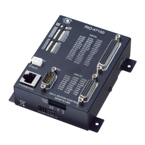
Chapter 2 Getting Started Layout RIO-4710x and RIO-4712x The mechanical layout and dimensions are the same for the RIO-4710x and RIO-4712x products (RIO- 47100, RIO-47122 etc). Figure 2.1: Outline of RIO-47100. Dimensions listed in the Appendix under: RIO Dimensions Chapter 2 Getting Started ▫ 11 RIO-47xxx Rev 1.0r... - Page 12 RIO-47142 The RIO-47142 has similar mechanical dimensions to the RIO-4710x and RIO-4712x products. The main difference is the dual Ethernet switch integrated into the RIO. Figure 2.2: Outline of the RIO-47142. Dimensions listed in the Appendix under: RIO Dimensions RIO-4720x Figure 2.3: Outline of RIO-4720x.
- Page 13 RIO-47300 Figure 2.4: Outline of the RIO-47300. Dimensions listed in the Appendix under: RIO Dimensions. Chapter 2 Getting Started ▫ 13 RIO-47xxx Rev 1.0r...
-
Page 14: Installing The Rio Board
Installing the RIO Board Installation of a complete, operational RIO system consists of 4 steps: Step 1. Configure jumpers Step 2. Connect power to the RIO Step 3. Install the communications software Step 4. Establish communications between the RIO and the host PC Step 1. - Page 15 Step 2. Connect Power to the RIO Most RIO models can be powered using either an auxiliary DC power supply or a PoE (Power over Ethernet) switch. These power options are selected by the user by placing four jumpers on either the “PoE”...
- Page 16 http://www.galil.com/download/manual/galilsuite/galilsuite.pdf Step 4. Establish Communications between RIO and the Host PC Ethernet For non-Auto MDIX RIO models , connect the RIO Ethernet port to your computer via an Ethernet crossover cable, or to a network hub by a straight through Ethernet cable. An IP address needs to be assigned via a DHCP server, through Galil's software, or via a serial cable using the command.
- Page 17 Analog Inputs(7-0) 0.0000,0.0000,0.0000,0.0000,0.0037,0.0012,0.0000,0.0000 Analog Outputs(7-0) 0.0000,0.0000,0.0000,0.0000,0.0000,0.0000,0.0000,0.0000 RIO Web Server The RIO has a built-in web server that can be accessed by typing the IP address of the controller into a standard web browser. The controller comes from the factory without any IP address assigned so a user must go through the steps outlined above to establish an IP address before the web-server is accessible.
-
Page 18: Chapter 3 Communication
Chapter 3 Communication Introduction The RIO has one RS-232 port and one Ethernet port. The RIO is capable of 100bT or a 10bT Ethernet connection. The RIO-47142 and RIO-47300 have dual port Ethernet switches. RS232 Port The RIO board has a single RS232 connection for sending and receiving commands from a PC or other terminal. - Page 19 The RIO supports two industry standard protocols, TCP/IP and UDP/IP. The board will automatically respond in the format in which it is contacted upon connection. TCP/IP is a "connection" protocol. The master must be connected to the slave in order to begin communicating.
- Page 20 2. The second method to assign an IP address is to use Galil Software. This procedure will vary depending on the software package. Refer to the user manual for the different software packages that support the RIO-47xxx. 3. The third method for setting an IP address is to send the command through the RS-232 port.
- Page 21 When the RIO acts as the master, the command is used to assign handles and connect to its slaves. The IP address may be entered as a 4 byte number separated with commas (industry standard uses periods) or as a signed 32 bit number. A port number may also be specified, but if it is not, it will default to 1000.
- Page 22 Unsolicited Message Handling Unsolicited messages are any messages that are sent from the controller that are not directly requested by the host PC. An example of this is a MG or TP command inside of a program running on the controller. Error messages are also “unsolicited” because they can come out at any time. There are two software commands that will configure how the controller handles these unsolicited messages: CW and CF.
-
Page 23: Modbus
Modbus An additional protocol layer is available for speaking to I/O devices. Modbus is an RS-485 protocol that packages information in binary packets that are sent as part of a TCP/IP packet. Modbus/TCP requires an Ethernet connection between master and slave. Modbus/TCP also requires that all slaves communicate with their masters over port 502. - Page 24 Example #1 – Using Methods 1 and 2 to set Outputs This example shows how a RIO master might connect to another slave RIO and toggle it's outputs on using Method 1 and Method 2 described above. Method 1 1. Begin by opening a connection to the slave assuming it has the IP address 192.168.1.120. This command would be issued to the RIO Master: IHB=192,168,1,120<502>2 This command opens a Modbus connection to the slave on handle “B”.
- Page 25 3. Send the appropriate MB command: Use function code 4 (this is specified by the PLC as well). Start at address 40006. Retrieve 4 Modbus registers. Note: There are two Modbus registers per a single analog input using 32-bit numbers. MBB=,4,40006,4,myanalog[] Array elements 0 and 1 will make up the 32-bit floating point value for analog input 3 and array elements 2 and 3 will combine for the value of analog input 4.
- Page 26 The RIO will respond to a request with function code $01 followed by a byte count (in hex), which describes the number of bytes of digital outputs being returned. The byte count can be calculated as follows: quanitity of outputs byte count= Equation 3.1: If the remainder of this equation is not 0, the byte count is instead calculated by:...
- Page 27 Function Code 3 ($03) - Read Holding Registers Modbus function code $03 is a request to read holding registers. The default configuration is to respond to this command with analog input register information. Function code 3 has very different behaviors depending on the configuration commands set. A synopsis and brief list of commands that effect how the RIO responds to function code 3 is in Table 3.5 below: Command...
- Page 28 Register Address 32-bit floating [volts] 16-bit integer [counts] Analog Input 0 Analog Input 0 Analog Input 1 Analog Input 2 Analog Input 1 Analog Input 3 Analog Input 4 Analog Input 2 Analog Input 5 Analog Input 6 Analog Input 3 Analog Input 7 Analog Input 4 Analog Input 5...
- Page 29 Register Address 32-bit floating [volts] 16-bit integer [counts] Analog Output 0 Analog Output 0 Analog Output 1 Analog Output 2 Analog Output 1 Analog Output 3 Analog Output 4 Analog Output 2 Analog Output 5 Analog Output 6 Analog Output 3 Analog Output 7 Analog Output 4 Analog Output 5...
- Page 30 Coil Addresses Digital Output 0 Digital Output 1 Digital Output 2 Digital Output 3 Digital Output 4 Digital Output 5 Digital Output 6 Digital Output 7 Table 3.9: Digital output coil for function code 7 Function Code 15 ($0F) – Write Multiple Coils Modbus function code ($0F) is a request to write multiple coils.
- Page 31 Modbus Exceptions As a Master An RIO-47xxx configured as a master can query the function code of the last response it received using the _MW0 operand. In addition, the _MW0 operand can be used to determine if an exception has occurred. The _MW1 operand can be used to determine why the exemption occurred.
- Page 32 Coil # Value Byte of Response Word Coil # Value Note: bits in the response marked 'X' are not valid coil response data, but are instead 0's that fill the remainder of the byte As a result, the Galil master's would have the following information stored in it's arrays: array[0]=205 array[1]=12 Function Code 2 ($02)
- Page 33 Function Code 3 ($03) Assume the status analog inputs on the Galil slave in descending order from 0-7 are as follows: .4822, .9753, 1.4673, 1.9629, 2.4622, 2.9675, 3.4583, 3.9600 And that the command issued from the Galil Master is MBm=,3,2,4,array[] The Modbus request and response packets would form as follows.
- Page 34 Slave Response Master Request 32-bit Floating Point (MI 0) 16-bit Decimal (MI 1) Field Name Field Name Volts Field Name Counts Function $04 Function Function Starting Address High $00 Byte Count Byte Count Starting Address Low $02 RegVal2 High 1.0000 RegVal2 High 19661 Quantity of Registers High RegVal2 Low...
- Page 35 Master Request Slave Response Field Name Field Name Function Function Starting Address High Starting Address High Starting Address Low Starting Address Low Register Value High Register Value High Register Value Low $AA Register Value Low Function Code 7 ($07) Assume the status digital outputs on the Galil slave in descending order from 15-0 are as follows: 0101010110101010 And that the command issued from the Galil Master is MBm= ,7,array[] The Modbus request and response packets would form as follows:...
- Page 36 Function Code 16 ($10) – Write Multiple Registers Example 1 Assume the desired setting for digital outputs on the Galil slave in descending order from 15-0 are as follows: 0101010110101010 And that the command issued from the Galil Master is MBm= ,16,2,4,array[], where array[] contains [$40A0,$0000,$4040,$0000].
- Page 37 As a result, the Galil slave will have analog output 2 set to 5V and analog output 3 set to 3V. Analog I/O Ranges The analog inputs and outputs range from different values depending on the configuration of the RIO. This information is specifically important when using the RIO to communicate as a modbus slave and MI is set to 1.
-
Page 38: Data Record
Data Record QR and DR Commands The RIO can provide a block of status information back to the host computer in a single Ethernet packet using either the QR or DR commands. The QR command returns the Data Record as a single response. - Page 39 ZD data – user configurable variable RIO-47300 Data Record DATA TYPE ITEM byte of header byte of header byte of header byte of header Sample number Error Code General Status Analog Out Channel 0 (counts) Analog Out Channel 1 (counts) Analog Out Channel 2 (counts) Analog Out Channel 3 (counts) Analog Out Channel 4 (counts)
- Page 40 These may be signed or unsigned words depending on the AQ setting on the RIO-4712x. For example, if the bytes received from the data record packet for analog input 0 were 00 80, it could have the following meaning, depending on Little Endian AQ 0,1 AQ 0,2...
-
Page 41: Chapter 4 I/O
Chapter 4 I/O Introduction Each RIO comes with a different set of default outputs types and quantity. Use Table 1.1 and Table 4.1 below to find out what default outputs come with your specific model. The interrogation command, TZ, allows the user to get a quick view of the I/O configuration and bit status. Specifications Access to I/O points is made through either the High Density D-Sub connectors on the top of the unit or through screw-terminal points, depending on your model. - Page 42 For wiring and electrical information, see the individual sections below which individually describes each type of output: 500mA Sourcing, 25mA Sinking, and 25mA Sourcing. Each of these are wired differently and have separate constraints, so read each section carefully before wiring. Note: For the following sections, “n”...
- Page 43 Figure 4.3: 500mA Sourcing wiring diagram for Bank 2, DO[23:16] 25mA Low Power Sinking Outputs (LSNK) The 25mA sinking option, referred to as lower power sinking (LSNK), are capable of sinking up to 25mA per output. The voltage range for the outputs is 5-24 VDC. These outputs should not be used to drive inductive loads directly.
- Page 44 Figure 4.6: 25mA Sinking wiring diagram for Bank 2, DO[23:16] 25mA Low Power Sourcing Outputs (LSRC) The 25mA sourcing option, referred to as lower power sourcing (LSRC), are capable of sourcing up to 25mA per output. The voltage range for the outputs is 5-24 VDC. These outputs should not be used to drive inductive loads directly.
- Page 45 Figure 4.9: 25mA Sourcing wiring diagram for Bank 2, DO[23:16] OUTC jumpers The OUTC jumpers can be used when an external power supply is not desired for digital outputs 8-15. These low power outputs can use the internal +5V from the RIO instead of an external supply. To do this, place a jumper on the pins labeled OUTC as shown in Figure 4.10.
- Page 46 Input Common RIO-471xx Bank 0, DI[7:0] INC0 Bank 1, DI[15:8] INC1 RIO-472xx Bank 0, DI[7:0] INC0A Bank 1, DI[15:8] INC1A RIO-47300 Bank 0, DI[7:0] INC0A Bank 1, DI[15:8] INC1A Bank 2, DI[23:16] INC2A Table 4.2: List of Input Commons for each Bank given the RIO model. Although rare, it is sometimes desired that optoisolation is bypassed.
- Page 47 Figure 4.11: Digital Input wiring for Bank 0, DI[7:0] Figure 4.12: Digital Input wiring for Bank 1, DI[15:8] Figure 4.13: Digital Input wiring for Bank 2, or DI[23-16] Input Current Limitations The current for an optoisolated input shall not exceed 11mA. Some applications may require the use of an external resistor (R) to limit the amount of current for an input.
- Page 48 1mA< <11mA R+2200Ω Equation 3.4: Current limitation requirements for each input. Figure 3.14: Wiring diagram showing how to put R in series between Vs and INCn/INCnA to limit current through the bank. Where n= 0, 1, and 2 representing input banks INC0/INC0A, INC1/INC1A, or INC2A m= [7:0], [15:8], and [23:16] depending on the bank of INCn/INCnA Chapter 4 I/O ▫...
- Page 49 INC jumpers The INC jumpers can be used when an external power supply is not desired to power the digital inputs. When INC jumpers are installed, example shown in Figure 4.15, the Input Common pins are internally connected to the RIO +5V reference signal. Each RIO model has a slightly different labeling scheme for these jumpers, so use Table 4.3 as a reference for the INC Jumper Labels for your model.
- Page 50 Figure 4.16: Wiring diagram with INC jumpers installed on the RIO-47100 Figure 4.17: Wiring diagram with INC jumpers installed on the RIO-47200 Figure 4.18: Wiring diagram with INCnA/INCnB jumpers installed on the RIO-47300 Chapter 4 I/O ▫ 50 RIO-47xxx Rev. 1.0r...
- Page 51 Pulse Counter Input Digital input 3 (DI3) is a special purpose input that (when enabled) is used to count pulses coming in. To enable the pulse counter, the PC command must be issued with the following syntax: where n=0 (default) input DI3 is a general purpose input n=1 sets input DI3 to be a rising edge pulse counter (also clears the pulse counter) n=-1 sets input DI3 to be a falling edge pulse counter (also clears the pulse counter) n=? returns the status of the pulse counter (0 if disabled, 1 if enabled)
- Page 52 Analog Outputs The RIO product line has two main types of analog outputs available for the different models. There are 0-5V and ±10V configurable analog output options. The ±10V configurable option can be ordered with 16-bit resolution and are 12-bit by default. Table 4.4 shows the models and available analog output configurations.
- Page 53 Analog Inputs The RIO product line has two main types of analog inputs available for the different models. There is a 0-5V analog input, and a ±10V configurable analog input. The ±10V configurable inputs can be ordered with 16 bit resolution. Table 4.5 shows the models and available analog input configurations. By default the RIO-472xx has 0-5V analog inputs.
- Page 54 Input Range AQ 0,1 Set input 0 to have ±5V input range AQ 1,2 Set input 1 to have ±10V input range AQ 2,3 Set input 2 to have 0-5V input range AQ 3,4 Set input 3 to have 0-10V input range Table 4.7: Setting Input Ranges on the RIOs with the ±10V configurable option Setting Differential Mode The AQ command also allows the RIO to change the configuration from the default 8 single ended analog...
-
Page 55: Chapter 5 Programming
Chapter 5 Programming Overview The RIO provides a versatile programming language that allows users to customize the RIO board for their particular application. Programs can be downloaded into the RIO memory, freeing up the host computer for other tasks. However, the host computer can send commands to the RIO at any time, even while a program is being executed. - Page 56 line in the case that 40characters is not enough for a single command (see example at the end of this section). Using Labels in Programs All RIO programs must begin with a label and end with an End (EN) statement. Labels start with the number (#) sign followed by a maximum of seven characters.
- Page 57 Note: The NO command also works to comment programs. The inclusion of the apostrophe or NO commands will require process time by the RIO board. Using REM Statements with the Galil Terminal Software When using Galil software to communicate with the RIO, REM, as in remark, statements may also be included.
-
Page 58: Executing Programs - Multitasking
Executing Programs - Multitasking The RIO can run up to 4 independent programs or threads simultaneously. They are numbered 0 thru 3, where 0 is the main thread. The main thread differs from the others in the following ways: 1. Only the main thread, thread 0, may use the input command, IN. 2. - Page 59 the RIO board and the contents of the program, array, and variable space. Operands also contain important status information, which can help to debug a program. Trace Commands The trace command causes the RIO to send each line in a program to the host computer immediately prior to execution.
-
Page 60: Program Flow Commands
Instruction Interpretation List Program 000 #A Program Label 001 SD14 Set bit 14 high 002 SB15 Set bit 15 high 003 MG”DONE” Print message 004 EN :XQ #A Execute #A ?001 SD14 Error on Line 1 :TC1 Tell Error Code 130 Unrecognized Command This command doesn’t :MG_ED... - Page 61 Examples: Interrupt Instruction Interpretation Program Label Execute #B in thread 1 XQ#B,1 II1,0,-1&3 #ININT1 in thread 0 when input 1 low and input 3 high II2,1,-5&10 #ININT2 in thread 1 when input 5 low and input 10 high AI 13&14 Trippoint on inputs 13 and 14 #LOOP;JP#LOOP Pseudo program –...
- Page 62 Conditional Jumps The RIO provides Conditional Jump (JP) and Conditional Jump to Subroutine (JS) instructions for branching to a new program location based on a specified condition. The conditional jump determines if a condition is satisfied and then branches to a new location or subroutine. Unlike event triggers such as the AI command, the conditional jump instruction does not halt the program sequence.
- Page 63 Note: Each condition must be placed in parentheses for proper evaluation by the RIO. In addition, the RIO executes operations from left to right. For example, using variables named V1, V2, V3 and V4: JP #TEST, (V1<V2) & (V3<V4) In this example, this statement will cause the program to jump to the label #TEST if V1 is less than V2 and V3 is less than V4.
- Page 64 Nesting IF Conditional Statements The RIO allows for IF conditional statements to be included within other IF conditional statements. This technique is known as 'nesting' and the RIO allows up to 255 IF conditional statements to be nested. This is a very powerful technique allowing the user to specify a variety of different cases for branching.
- Page 65 Auto-Start Routine The RIO has a special label for automatic program execution. A program that has been saved into the RIO non-volatile memory can be automatically executed upon power up or reset, simply by beginning the program with the label #AUTO. Note: The program must be saved into non-volatile memory using the command, BP.
- Page 66 Example - Command Error Instruction Interpretation #BEGIN Begin main program IN "ENTER THE OUTPUT (0-15)", OUT Prompt for output number SB OUT Set the specified bit JP #BEGIN Repeat End main program #CMDERR Command error utility Check if error on line 3 JP#DONE,_ED<>3 JP#DONE,_TC<>6 Check if out of range...
- Page 67 Example - Command Error w/Multitasking Instruction Interpretation Begin thread 0 (continuous loop) JP#A End of thread 0 Begin thread 1 Create new variable N=17 SB N Set the 17th bit, an invalid value Issue invalid command End of thread 1 #CMDERR Begin command error subroutine If error is out of range (SB 8)
-
Page 68: Mathematical And Functional Expressions
Mathematical and Functional Expressions Mathematical Operators For manipulation of data, the RIO provides the use of the following mathematical operators: Operator Function Addition Subtraction Multiplication Division & Logical And (Bit-wise) Logical Or (On some computers, a solid vertical line appears as a broken line) Parenthesis Modulus Mathematical operations are executed from left to right. - Page 69 :MG var;' Print result 1120000.0000 :var= var/10;' Divide by 10 to add in decimal :MG var;' Print correct result 112000.0000 Bit-Wise Operators The mathematical operators & and | are bit-wise operators. The operator, &, is a Logical And. The operator, |, is a Logical Or. These operators allow for bit-wise operations on any valid RIO numeric operand, including variables, array elements, numeric values, functions, keywords, and arithmetic expressions.
-
Page 70: Variables
Functions Function Description @SIN[n] Sine of n (n in degrees, with range of -32768 to 32767 and 16-bit fractional resolution) @COS[n] Cosine of n (n in degrees, with range of -32768 to 32767 and 16-bit fractional resolution) @TAN[n] Tangent of n (n in degrees, with range of -32768 to 32767 and 16-bit fractional resolution) ... -
Page 71: Operands
POINT Invalid Variable Names REALLONGNAME ; Cannot have more than 8 characters ; Cannot begin variable name with a number STAT Z ; Cannot have spaces in the name Assigning Values to Variables: Assigned values can be numbers, internal variables and keywords, functions, RIO board parameters and strings;... -
Page 72: Arrays
Operand Function *Returns serial # of the board. *Returns the number of arrays available *Returns the number of available labels for programming *Returns the available array memory *Returns the number of available variables TIME Free-Running Real Time Clock (Resets with power-on). Note: TIME does not use an underscore character (_) as other keywords. - Page 73 Using a Variable to Address Array Elements An array element number can also be a variable. This allows array entries to be assigned sequentially using a counter. For example: Instruction Interpretation Begin Program COUNT=0;DM POS[10] Initialize counter and define array #LOOP Begin loop WT 10...
-
Page 74: Output Of Data (Numeric And String)
Command Summary - Automatic Data Capture Command Description n[],m[],o[],p[] Selects up to four arrays for data capture. The arrays must be defined with the DM command. Selects the type of data to be recorded, where type1, type2, type3, and type1,type2,type3,type4 type 4 represent the various types of data (see table below). - Page 75 MG "The Final Value is", RESULT In addition to variables, functions and commands, responses can be used in the message command. For example: MG "The input is", @IN[1] Formatting Messages String variables can be formatted using the specifier, {Sn} where n is the number of characters, 1 thru 6.
- Page 76 Summary of Message Functions: Function Description " " Surrounds text string {Fn.m} Formats numeric values in decimal n digits to the right of the decimal point and m digits to the left Formats numeric values in hexadecimal {$n.m} {^n} Sends ASCII character specified by integer n Suppresses carriage return/line feed {Sn} Sends the first n characters of a string variable, where n is 1 thru 6.
-
Page 77: Programmable I/O
:V1=10 Assign V1 :V1= Return V1 0000000010.0000 Default format :VF2.2 Change format :V1= Return V1 10.00 New format :VF-2.2 Specify hex format :V1= Return V1 $0A.00 Hex value :VF1 Change format :V1= Return V1 Overflow Local Formatting of Variables VF command is a global format command that affects the format of all relevant returned values and variables. - Page 78 Instruction Interpretation OB1,POS Set Output 1 if the variable POS is non-zero. Clear Output 1 if POS equals 0. OB2,@IN [1] Set Output 2 if Input 1 is high. If Input 1 is low, clear Output 2. OB3,@IN[1]&@IN[2] Set Output 3 only if Input 1 and Input 2 are high. OB2,COUNT [1] Set Output 2 if element 1 in array COUNT is non-zero.
- Page 79 These integer values will also be returned when accessing the analog inputs by the API calls in C/C++ or Visual Basic. The AQ command also configures the analog inputs to be either 8 single ended (default) or 4 differential inputs. The AA command is a trippoint that halts program execution until the specified voltage on an analog input is reached.
- Page 80 Command Description Analog Input for feedback Analog Output for control Proportional Gain Derivative Gain Integral Gain Integrator Limit Deadband Control Loop Update Rate Commanded Setpoint Tell Error Analog Input Range Analog Output Range *Note – All PID parameters are burnable except PS, DB, AQ, and DQ. If you issue a BN with the PID’s enabled the default values for PS,DB,AQ, and DQ will be in effect upon power up.
-
Page 81: Real Time Clock
Note: When the Process Control Loop is enabled, the Analog output voltage is normalized to half of the total voltage input. For instance, with a 0-5V analog input range such as the RIO-47100 – the voltage is normalized to 2.5V. This allows the output to go below 2.5 to compensate for a negative error and above 2.5V to compensate for positive error. -
Page 82: Appendix
Appendix Electrical Specifications Input/Output Digital I/O See Chapter 4 I/O. DAC Output Current 4mA max output per channel +5V Reference 10mA max output 47120: ±12V out 10mA max output 47x42: ±12V out 10mA max output Power Requirements for EXT/AUX Power Option Model Input Voltage Range Minimum Power*... -
Page 83: Certifications
Certifications The RIO-471xx is certified for the following when the product or package is marked. http://www.galilmc.com/products/ce_documents/rio47000_ce_dc.pdf ROHS ROHS Compliant Ordering Options The RIO-47xxx can be ordered in many different configurations and with different options. This section provides information regarding the different options available on the RIO-47xxx. For more information on pricing and how to order an RIO with these options, see our RIO-47xxx part number generator on our website. - Page 84 -422 This option allows the RIO to communicate via RS-422 instead of RS-232. Description Description RTS- RTS+ TXD- TXD+ RXD- RXD+ CTS- CTS+ Part number ordering example: RIO-47100-422 -RTC RIO models with Expanded Memory (See if your model does in Table 1.1) come standard with some real time clock features.
- Page 85 Part number ordering example: RIO-47200-(1LSNK,2LSRC), where 1LSNK: Outputs 0-7 low power sinking 2LSRC: Outputs 8-15 low power sourcing -QUAD, -SSI, and -BiSS Most RIO models utilize Digital Inputs 12,13,14 and 15 and Digital Outputs 12,13,14 and 15 as encoder inputs. These digital inputs and outputs will not be available as standard digital I/O when the -QUAD, -SSI, or BiSS option is ordered.
- Page 86 Special Note for RIO-47300 The RIO-47300 allows for QUAD, SSI, or BiSS through an expanded board as shown in Figure A.2 below. Figure A.2: DMC-47300 Quad, SSI, and BiSS Option dimension changes -QUAD Pinout RIO-47122 & RIO-47142 RIO-47122 RIO-47142 Label Encoder Signal DO14 Channel 0 A+...
- Page 87 RIO-47300 Label Encoder Signal Channel 0 A+ Channel 0 A- Channel 0 B+ Channel 0 B- Channel 1 A+ Channel 1 A- Channel 1 B+ Channel 1 B- +5V reference Ground Table A.4: The screw-terminal labels for the encoder connections -SSI/BiSS Pinout RIO-47122 &...
- Page 88 -PWM The DY,PM and FQ commands are used on the RIO-47xxx to output 3.3 V PWM signals on Digital Outputs 14 and 15. These outputs are normally optoisolated, which limits the PWM frequency to a maximum of 50 Hz. The -PWM option bypasses optoisolation and provides buffered outputs for Digital Outputs 14 and 15, increasing the maximum frequency to 20 kHz.
- Page 89 Electrical Specifications for DO15:14 with –PWM option Output Voltage Range: 0V to 3.3V Current output - Sink/Source: 20 mA (Max) Part number ordering example: RIO-47102-PWM Figure A.5: -PWM option This option changes digital input 3 (DI3) to a high speed digital input. It is available on expanded memory RIO models (RIO-47002 and RIO-47300) as a standard option.
- Page 90 -(AI_10v12Bit) This option changes the analog inputs on the RIO-472xx to accept +-10V analog signals with 12 bit resolution. The range of the analog inputs can be changed with the AQ command, similar to the RIO-4712x. Part number ordering example: RIO-47200-(AI_10v12bit) -(AI_10v16Bit) This option changes the analog inputs on the RIO-472xx to accept +-10V analog signals with 16...
- Page 91 (8AO_5v12bit) This option adds 12 bit 0-5V analog outputs via the SCB-48608 on the RIO-472xx. See 0-5V Analog Outputs in Chapter 4 for more information. Part number ordering example: RIO-47200-(8AO_5v12bit) Qty 8, 0-5V analog outputs with 12 bit resolution. (8AO_10v12bit) This option adds 12 bit ±10V configurable analog outputs via the SCB-48608 on the RIO-472xx.
- Page 92 -24ExIn & -24ExOut The I/O capability of the RIO-47300 can be expanded with an additional 24 digital optoisolated inputs or outputs. NOTE: The extended I/O is configured as either inputs or outputs and should be wired based on the option ordered. For alternative configurations contact Galil. Dimensions Figure A.7: RIO-47300-27ExIn/Out Dimensions Pin-outs...
- Page 93 Electrical Specifications Inputs (-24ExIn Option) The -24ExIn option provides an additional 24 optoisolated inputs with the same electrical specifications as listed under Digital Inputs, Electrical Specifications, pg 46. Figure A.8 - Figure A.10 provide the wiring diagrams for these inputs. Figure A.8: Wiring diagram for DI[31:24], Bank 3 Figure A.9: Wiring diagram for DI[39:32], Bank 4 Figure A.10: Wiring diagram for DI[47:40], Bank 5...
- Page 94 Figure A.11: INC jumpers wiring diagram for input Banks 3-5 Outputs (-24ExOut Option) The -24ExOut option provides an additional 24, 500mA sourcing, optoisolated outputs with the same electrical specifications as listed under Digital Outputs, 500mA Sourcing Outputs (HSRC), pg 42. Figure A.12 - Figure A.14 provide the wiring diagrams for digital output Banks 3-5.
-
Page 95: Onnectors For Rio-47 Xxx
Connectors for RIO-47xxx RIO-471xx - 44 pin D-Sub Connector Pin Label Description Label Description Label Description DI15 Digital Input 15 No connect / INC1B DI14 Digital Input 14 DI12 Digital Input 12 DI13 Digital Input 13 DI11 Digital Input 11 Digital Input 9 DI10 Digital Input 10... - Page 96 RIO-472xx - Screw Terminals Label Description Label Description 18-36 18-36VDC logic power input DI10 Digital Input 10 Return side of logic power input DI11 Digital Input 11 AGND Analog Ground DI12 Digital Input 12 AGND Analog Ground DI13 Digital Input 13 Analog Input 0 DI14 Digital Input 14...
- Page 97 RIO-47300 – Screw Terminals Row 1 Row 2 Row 3 Label Description Label Description Label Description 9-48 9-48VDC logic power input Digital ground Digital ground -12V output +5V output analog +12V output reference reference reference AGND Analog ground Analog input 0 Analog input 1 Analog input 2 Analog input 3...
- Page 98 RS-232 Port: DB-9 Pin Male The location of the RS-232 on the board varies slightly with product. Use the table below as reference: Product Location RIO-471xx RIO-472xx RIO-47300 The RS232 uses a standard connector and cable, 9-Pin: Signal No Connect No Connect Ground No Connect...
- Page 99 On Board Connector Common Mating Connectors Crimp Part Number Type MOLEX# 39-31-0020 MOLEX# 39-01-2025 MOLEX# 44476-3112 2 Position The mating connectors listed are not the only mating connectors available from Molex. See http://www.molex.com/ the full list of available mating connectors. Appendix ▫...
-
Page 100: Jumper Descriptions
Jumper Descriptions RIO-4710x/4712x Jumper Label Function (If jumpered) MRST Master Reset enable. Returns RIO to factory default settings and erases non- volatile memory. Requires power-on or RESET to be activated. UPGD Used to upgrade the controller if the unit becomes unresponsive. 19.2 Set baud Rate to 19.2k (default without jumper is 115k) 10BaseT Ethernet Communication... - Page 101 JP13 INC0A Connects INC0A +5V and INC0B to GND INC0B JP14 INC1A Connects INC1A +5V and INC1B to GND INC1B JP15 INC2A Connects INC2A +5V and INC2B to GND INC2B Appendix ▫ 101 RIO-47xxx Rev 1.0r...
-
Page 102: Rio Dimensions
RIO Dimensions RIO-4710x & RIO-4712x Figure A.15: Dimensions for RIO-471xx (in inches) RIO-47142 Figure A.16: Dimensions of the RIO-47142 (in inches) Appendix ▫ 102 RIO-47xxx Rev. 1.0r... - Page 103 RIO-472xx Figure A.17: Dimensions for RIO-472xx (in mm) RIO-47300 Figure A.18: Dimensions of RIO-47300 (in inches) Appendix ▫ 103 RIO-47xxx Rev 1.0r...
-
Page 104: Accessories
Accessories Product Description Low power switching power supply that comes with a 2-pin Molex PS-2.50-24 connector to allow for mating directly to the RIO. See specifications here: A3 - Power Supplies, pg 116. 26-pin D high-density male to screw terminals. ICS-48026-M Use 1 for each RIO-471x0 to break out analog signals 44-pin D high-density male to screw terminals. -
Page 105: List Of Other Publications
"Step by Step Design of Motion Control Systems" by Dr. Jacob Tal "Motion Control Applications" by Dr. Jacob Tal "Motion Control by Microprocessors" by Dr. Jacob Tal Contacting Us Galil Motion Control 270 Technology Way Rocklin, CA 95765 Phone: 916-626-0101 Fax: 916-626-0102 E-Mail Address: support@galilmc.com URL: www.galil.com Appendix ▫... -
Page 106: Training Seminars
Training Seminars Galil, a leader in motion control with over 500,000 controllers working worldwide, has a proud reputation for anticipating and setting the trends in motion control. Galil understands your need to keep abreast with these trends in order to remain resourceful and competitive. -
Page 107: Warranty
1 year warranty. In the event of any defects in materials or workmanship, Galil Motion Control will, at its sole option, repair or replace the defective product covered by this warranty without charge. -
Page 108: A1 - Scb-48206
A1 – SCB-48206 Description The SCB-48206 Signal Conditioning Board interfaces to up to six 3-wire RTD’s (Resistive Temperature Device). The SCB-48206 is designed to work with the RIO-4712x or RIO-47142. The SCB-48206 plugs directly into the Analog 26-pin high-density D-sub connector and will use Analog Inputs 0-5 on the RIO for the 6 RTD inputs. -
Page 109: Specifications
Specifications Number of Inputs 6 RTD inputs RTD input – Analog Input Map RTD[0:5] = AI[0:5] Output Range 0-5V Excitation Current 1 mA Input Range 18 – 230 Ω Temperature Range (100Ω RTD) -200 to 350 deg C If greater than 230Ω (350 deg C) is required, contact Galil. Wiring The SBC-48206 has qty 6, 3-wire RTD inputs. -
Page 110: Dimensions
Dimensions Figure A1.3: Dimensions for SCB-48206 Operation The SBC-48206 will send a 0-5V analog voltage to the RIO that is related to the resistance of the RTD. When using the SBC-48026, the analog inputs should be set to 0-5V inputs for the 6 RTD inputs. This is done with the AQ command with a setting of 3 (AQ n,3 –... - Page 111 AQ 3,3 AQ 4,3 AQ 5,3 AT0;'set initial time reference #Calc REM calculate resistance of RTD r0 = (1000*@AN[0])/21 r1 = (1000*@AN[1])/21 r2 = (1000*@AN[2])/21 r3 = (1000*@AN[3])/21 r4 = (1000*@AN[4])/21 r5 = (1000*@AN[5])/21 REM calculate deg C Tc0 = (r0-100)/0.385 Tc1 = (r1-100)/0.385 Tc2 = (r2-100)/0.385 Tc3 = (r3-100)/0.385...
- Page 112 AQ 2,3 AQ 3,3 AQ 4,3 AQ 5,3 AT0;'set initial time reference #Calc REM calculate resistance of RTD r0 = (1000*@AN[0])/21 r1 = (1000*@AN[1])/21 r2 = (1000*@AN[2])/21 r3 = (1000*@AN[3])/21 r4 = (1000*@AN[4])/21 r5 = (1000*@AN[5])/21 REM calculate deg C r=r0;JS#Celcius;Tc0 = Tc r=r1;JS#Celcius;Tc1 = Tc r=r2;JS#Celcius;Tc2 = Tc...
-
Page 113: A2 - Scb-48306/48316
A2 – SCB-48306/48316 Description The SCB-48306 and the SCB-48316 Signal Conditioning Board interface to up to 6 thermocouples. The SCB-483x6 boards are designed to work with the RIO-4712x or RIO-47142. The SCB-48316 provides thermocouple terminal connectors for the 6 thermocouple inputs, the SCB-48306 provides screw terminals inputs for the 6 thermocouple inputs. -
Page 114: Specifications
Specifications Number of Inputs 6 Thermocouple Inputs Thermocouple input – Analog Input Map TC[0:5] = AI[0:5] Range Type K (default) 0 – 345 deg C Type E 0 – 230 deg C Type J 0 – 270 deg C Type T 0 –... -
Page 115: Operation
Operation The SCB-483x6 will send an analog voltage to the RIO-4712x or RIO-47142 that is proportional to the temperature of the junction by the Voltage constant defined in the Specifications section. When using the SCB-483x6, the analog inputs should be set to 0-5V inputs for the thermocouple inputs. This is done with the AQ command with a setting of 3 (AQ n,3 –... -
Page 116: A3 - Power Supplies
A3 - Power Supplies Galil offers a power supply that can be used to power the RIO product line, the PS-2.50-24. This low power switching mode supplies come with a 2-pin Molex Mini-Fit, Jr connector to allow for mating directly to the RIO. PS-2.50-24 Electrical Specifications Power: 60 W Max...
Need help?
Do you have a question about the RIO-47 series RIO-47100 and is the answer not in the manual?
Questions and answers