oventrop R-Tronic RT B Installation And Operating Instructions Manual
Climate display device/control
Hide thumbs
Also See for R-Tronic RT B:
- Installation and operating instructions manual (88 pages) ,
- Operating instructions manual (36 pages) ,
- Instruction manual (12 pages)

Related Manuals for oventrop R-Tronic RT B


Summary of Contents for oventrop R-Tronic RT B
- Page 1 Valves, controls + systems “R-Tronic RT B / RTF B / RTFC K” “Aktor MH CON B / Aktor MD CON B” Installation and operating instructions “R-Tronic” Climate display device/control...
- Page 2 - 2 von 64 -...
- Page 3 Extent of supply Thank you for purchasing this wireless thermostat. Please check the delivery for completeness. It consists of the following components (depending on the ordered model): “R-Tronic RT B “ “R-Tronic RTF B “ (Temperature) (Temperature / Air humidity)
- Page 4 Mains adaptor with table stand (Item no.: 1150692) (Item no.: 1150694) optional for the models optional for the models “R-Tronic RT B" / "R-Tronic RTF B” “R-Tronic RT B“ / „R-Tronic RTF B” Window contact (Item no.: 1153070) Cover frame 88x88 mm (item no.
-
Page 5: Table Of Contents
General conditions of sales and delivery Installation and initial operation General installation advice Wall attachment of fixing plate “R-Tronic RT B / RTF B” (battery operation) Wall attachment fixing plate with flush-mounted power pack (type “RTFC K”) Installation with table stand and mains adaptor Installation of the wireless actuator “Aktor MH/MD CON B”... -
Page 6: General Information
NOTE Read installation and operating instructions in their entirety before installing the wireless thermostats “R-Tronic RT B”, “R-Tronic RTF B” or “R-Tronic RTFC K” and their accessories. This will allow an (energy) efficient use of the product. Please also take note of the brief instruction supplied with the product. -
Page 7: Safety Notes
(as recommendation for window airing). Please observe that only Oventrop accessories (power packs etc.) must be installed. Any use of the wireless controllers “R-Tronic RT B”, “R-Tronic RTF B” and “R-Tronic RTFC K” and the actuator outside the above applications will be considered as non- compliant and misuse. -
Page 8: Warnings And Their Meaning
Safety notes Warnings and their meaning This manual shows warnings for a safe installation and operation of the product, especially at text passages with action-related information. These warnings must be observed to avoid accidents, damage to property and malfunctions. The below hazard classification is, amongst others, based on the ISO 3864 standard and the international ANSI standard Z535.6. -
Page 9: Product Description
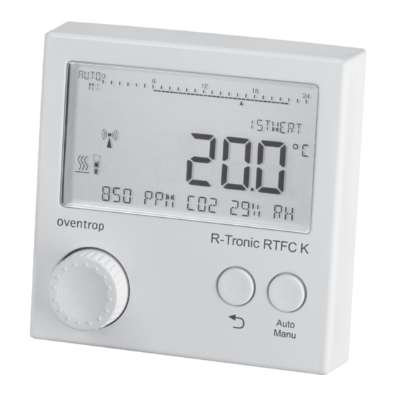
(100-240 V ~/50-60 Hz). “R-Tronic“ models: “R-Tronic RT B”: temperature control only, battery operated by default, power supply can also be carried out via a flush-mounted power pack or a mains adaptor which are available as optional accessory (item no.: 1150692 or 94). - Page 10 Product description Summary “R-Tronic” (Illustr. 2) Operating mode and time profile Display (illuminated): Text line: Symbols and supplies information on display units. - Measured values - Menu structure - Diagnosis (advice) Auto/Manu-button: Switching between the standard heating profiles Menu-button: Return-button: Navigation and nominal setting by turning (to the Previous menu level;...
- Page 11 Product description The radiator must be equipped with an electromotive actuator for the regulation of the heat output according to the required temperature (set value) set at the “R-Tronic”. The actuator receives and evaluates the corresponding control commands via a radio communication.
-
Page 12: Technical Data
+5°C up to +50°C For battery operation: Battery type AA 1.5 V Mignon LR6 Service life approx. 2 years “R-Tronic RT B / RTF B / RTFC K” Power supply: “RTFC K” with external power pack (100-240V / 50-60Hz) “RT B”, “RTF B” battery operation,... -
Page 13: Note Regarding Declaration Of Conformity
Subject to technical modifications! Note regarding declaration of conformity The company OVENTROP GmbH & Co. KG hereby declares that the “R-Tronic” and “Aktor MH CON B” respectively “Aktor MD CON B” comply with the basic requirements and other relevant provisions of the guidelines 2014/53/EU (RED). -
Page 14: Installation And Initial Operation
Installation and initial operation Installation and initial operation General installation advice The climate display device/control “R-Tronic” should be installed at a location where a good circulation of air is guaranteed. If possible, the controller should be mounted onto an inner wall or a pillar at a height of 140 cm to 170 cm. Please make sure that the room controller is not affected by other heat sources (such as sunlight or heating devices next to it). -
Page 15: Wall Attachment Of Fixing Plate "R-Tronic Rt B / Rtf B" (Battery Operation)
Wall attachment of fixing plate “R-Tronic RT B / RTF B” (battery operation) For the models “R-Tronic RT B” and “R-Tronic RTF B”, power is either supplied by batteries, a flush-mounted power pack or a mains adapter with table stand (available as accessories). -
Page 16: Wall Attachment Fixing Plate With Flush-Mounted Power Pack (Type "Rtfc K")
Installation and initial operation Wall attachment fixing plate with flush-mounted power pack (type “RTFC K”) DANGER Risk of electric shock! As the flush-mounted power pack has to be connected to the current supply of the house, there is a risk of an electric shock. •... -
Page 17: Installation With Table Stand And Mains Adaptor
Installation and initial operation Installation with table stand and mains adaptor CAUTION Risk of fire by short circuit! There is a risk of overcharging of the batteries (types “RT B” and “RTF B”) if the operating unit is equipped with batteries and is connected to the 230 V network via the table stand. -
Page 18: Installation Of The Wireless Actuator "Aktor Mh/Md Con B
M 30 x 1.5. An adapter set (item no. 1011445) for valves with connection threadM 30 x 1 is available from Oventrop. Keep a spanner (size 32) available forinstallation. The version “Aktor MD CON B” can be fitted without adapter to the integrated distributors and thermostatic radiator valves with squeeze connection of the company Danfoss, series RA and connection fittings VHS. - Page 19 is retracted to facilitate installation of the actuator. - 19 von 64 -...
- Page 20 Installation and initial operation (Illustr. 10) Radiator valve Collar nut of the actuator (M30 x 1.5) without image: squeeze connection ► The wireless actuator is now ready for the “teach in” process. (Illustr. 11) “Push rod” (retracted) NOTE The “push rod” (see illustr. above) may be extended before installation - for instance if the actuator has been mounted onto a radiator before.
-
Page 21: Creation Of The Radio Communication "R-Tronic" And Actuator
Installation and initial operation Creation of the radio communication “R-Tronic” and actuator After having connected the operating unit “R-Tronic” and the actuator to the power supply, a radio communication between both components has to be created (the so- called “teach in” process). 4.6.1 Setting language, date and time After having connected the operating unit to the power supply, the setting routine for the language (see paragraph 5.4.3), date (year, month, day) and the current time... -
Page 22: Adaptation Of The "Aktor Mh/Md Con B" To The "R-Tronic
Installation and initial operation 4.6.2 Adaptation of the “Aktor MH/MD CON B” to the “R-Tronic” 1. Go to the main menu by pressing the menu-button for at least 1 second, until TIME PROFILE will be displayed. 2. Turn the menu-button to the right until SETTINGS will be indicated on the display. - Page 23 Installation and initial operation NOTE of an unsuccessful “teach in” process If you do not succeed in pressing the “teach in”/adjustment button of the actuator within the 30 seconds countdown (countdown expired before, no radio signal), TEACH IN will be displayed again. The “teach in” process may be repeated now. The “teach in”...
- Page 24 Installation and initial operation The warning symbol signalizes that the calibration respectively “adjustment run” of the actuator still have to be carried out (see following paragraph 4.7). The red info LED of the actuator flashes red continuously. It will only turn off after adjustment of the valve.
-
Page 25: Calibration Of The Actuator ("Adjustment Run")
Installation and initial operation Calibration of the actuator (“adjustment run”) After having created the radio communication successfully, the actuator has to be adjusted to the valve of your radiator. As the “Valve OPEN”/”VALVE CLOSED” position of radiator valves may vary slightly, the individual position of your radiator has to be determined by the actuator. -
Page 26: Window Contacts (Accessory): "Teach In" Process And Installation
Installation and initial operation Window contacts (accessory): “Teach in” process and installation The wireless thermostat “R-Tronic” has to be mains operated for use of window contacts. Illustr. 19 Wireless window contacts (type “FK-C F” item no. 1153070) allow for an automatic control of the wireless actuators which have been adapted to the “R-Tronic”. - Page 27 Installation and initial operation Illustr. 21 Now the “teach in” button (1d) at the window contact has to be pressed within this countdown. As the button is recessed on the reverse side of the casing, use a pointed object, such as a screwdriver or a paper clip. The message SUCCESS which will shortly appear on the “R-Tronic”...
- Page 28 Installation and initial operation When the window is opened, the contact in the wireless sensor module (1) will be interrupted and a signal will be transmitted to the wireless thermostat “R-Tronic”. Illustr. 23 When using several window contacts, all radiator valves will be closed if only one window contact is interrupted.
-
Page 29: Standard Heating Profiles And Temperature Setting
Installation and initial operation Standard heating profiles and temperature setting When putting the “R-Tronic” into operation, the standard profile will always be active and adjust the room temperature to a constant value of 20°C (continuous heating operation = PROFILE ON). The activity of the standard profile is displayed by a continuous line below the timeline across the complete 24-hour scale (MANU will be displayed): This basic setting can be adjusted according to your requirements or be inactivated... - Page 30 Installation and initial operation If you do not wish a constant heating or setback operation according to only one temperature setting, the pre-defined heating profile PROFILE DAY / NIGHT can be activated. The room temperature will be reduced to 17°C between 22.00 h and 6.00 h and be adjusted to the “comfort temperature”...
-
Page 31: Setting Of The Required Temperature Via Nominal Setting
Installation and initial operation 4.9.2 Setting of the required temperature via NOMINAL SETTING The room temperature cannot only be set via PROFILE ON, PROFILE OFF and PROFILE DAY / NIGHT but also via a direct nominal setting. NOTE regarding the effectiveness of set values An active heating profile will be influenced by the nominal setting for a short time. -
Page 32: Operation And Menu Structure Of The "R-Tronic
Operation Operation and menu structure of the “R-Tronic” The following chapter will show you how to set your required room temperature comfortably via your central “R-Tronic” operating unit. You can find information on general and special settings, such as programming of your time controlled individual profiles, etc. -
Page 33: Menu "Time Profile
Operation Menu “Time profile” Menu structure: (Illustr. 29) MAIN MENU TIME PROFILE FUNCTIONS SETTINGS INFORMATION TEMPERATURES PROGRAMME SELECTION PROGRAMMING PROFILE ON / OFF INDIVIDUALPROFIL 1-5 PROFILE DAY/NIGHT INDIVIDUAL PROFILE 1-5 The standard heating profiles PROFILE ON, PROFILE OFF, PROFILE DAY / NIGHT (see paragraph 4.8) stored in the “R-Tronic”... - Page 34 Operation Confirm your entry by pressing the menu-button and select your COMFORT TEMPERATURE to which the room shall be adjusted by the “R-Tronic” within HEATING PERIOD 1. (Illustr. 31) 3. Confirm your entry by pressing the menu-button and determine the end of HEATING PERIOD 1.
- Page 35 Operation 6. Select your COMFORT TEMPERATURE again: (Illustr. 35) 7. Define the end of HEATING PERIOD 2: (Illustr. 36) 8. Enter a SETBACK TEMPERATURE again: (Illustr. 37) 9. If you want to set HEATING PERIOD 3, please proceed as described above. Having entered all required heating periods, the message SAVE will shortly appear on the “R-Tronic”...
- Page 36 Operation NOTE After each defined heating period you have the option to complete programming prematurely after entry of the respective SETBACK TEMPERATURE (and to set only one or two heating periods per day). To do so, turn the menu-button slightly to the right. The message READY which is confirmed by pressing the menu-button will appear on the “R-Tronic”...
- Page 37 Operation MO – FR / SA – SU (setting option 2) Up to three heating periods for one workday valid from Monday to Friday, as well as a weekend profile for Saturday and Sunday, can be programmed here. 1. Starting from the submenu TIME PROFILE ► PROGRAMMING, select one of the five individual profiles by pressing the menu-button.
-
Page 38: Menu "Temperatures
Operation Menu “Temperatures” Menu structure: (Illustr. 39) MAIN MENU TEMPERATURES FUNCTIONS SETTINGS TIME PROFILE INFORMATION COMFORT TEMPERATURE … SETBACK TEMPERATURE … LIMIT MIN/MAX … TEMPERATURE UNIT The COMFORT TEMPERATURE and SETBACK TEMPERATURE of the standard heating profiles can be set in the submenu TEMPERATURES according to your requirements. -
Page 39: Setting Of The General Temperature Range
Operation 5.2.1 Setting of the general temperature range The submenu TEMPERATURES offers the option to define a general temperature range for all heating and setback periods and their respective cycles. The “R-Tronic” is preset at works to a maximum range between 6 °C and 35 °C. You can change these values via the function TEMPERATURES ►... -
Page 40: Menu "Functions
Operation Menu “Functions” Menu-structure: (Illustr. 42) MAIN MENU TIME PROFILE TEMPERATURES FUNCTIONS SETTINGS INFORMATION BOOST … VACATION … PARTY MODE … CHILD-PROOF LOCK … VALVE PROTECTION … Special “R-Tronic” functions which are described below, can be configured in the submenu FUNCTIONS: 5.3.1 BOOST (rapid heating) A temporary maximum heating up of the radiator may be useful to generate a comfortable surrounding area. -
Page 41: Vacation Function (Setback Temperature During Absence)
Operation 5.3.2 Vacation function (setback temperature during absence) You may use the “vacation function” if you will be absent for several days or weeks and want to define a lower setback temperature for a room for the sake of energy saving. -
Page 42: Party Mode" (Required Temperature During A Defined Period)
Operation 5.3.3 “Party mode” (required temperature during a defined period) The “party mode” adjusts the room to your required temperature during a defined period. The heating profile will be inactivated temporarily. Contrary to the temperature modification via a set value (see paragraph 4.8.2), the “party mode” will be active during a certain period which is adjustable between one and 24 hours. -
Page 43: Child-Proof Lock (Operation Lock)
Operation 5.3.4 Child-proof lock (operation lock) The settings of the “R-Tronic” can be secured via this function. Please proceed as follows: 1. You are in the submenu FUNCTIONS. Confirm this selection by pressing the menu-button. BOOST will be displayed as before. Turn the menu-button to the right until CHILD-PROOF LOCK will be displayed. -
Page 44: Menu "Settings
Operation Menu “Settings” Menu structure: (Illustr. 46) MAIN MENU TIME PROFILE TEMPERATURES FUNCTIONS SETTINGS INFORMATION INSTALLATION … DATE / TIME … LANGUAGE … DISPLAY … CONTROL … SUMMER-/ WINTER TIME … LIGHTING … ROOM DESIGNATION … FACTORY SETTING … RESET …... -
Page 45: Date And Time
Operating 2. Turn the menu-button slightly to the right and confirm the selection TEACH OUT. As for the “teach in” process, a running countdown of 30 seconds will be displayed. 3. Now the “teach in”/adjustment button at the actuator has to be pressed shortly (!) within this countdown. -
Page 46: Language
Operation 5.4.3 Language You may select between the menu languages German, English, French, Spanish, Italian and Polish. This is done as follows: 1. You are in the submenu SETTINGS. Confirm the selection by pressing the menu- button. INSTALLATION will be displayed as before. 2. -
Page 47: Summer-/Winter Time
Operation 5.4.6 Summer-/winter time The automatic switching to European summer or winter time can be activated or deactivated here. To do so, select SETTINGS ► SUMMER-/ WINTER TIME ► AUTO ADJUSTMENT via the menu-button and decide whether the automatic switching shall be activated or deactivated (turn the menu-button and confirm). -
Page 48: Factory Settings "R-Tronic" And "Aktor Mh/Md Con B
Operation 5.4.9 Factory settings “R-Tronic” and “Aktor MH/MD CON B” It might be useful to restore the factory settings of the “R-Tronic” and the actuator if, for instance, wrong settings that do not guarantee an efficient heat control of your room were stored by mistake. -
Page 49: Menu "Room Climate" (Only "R-Tronic Rtfc K")
Operation Menu “Room climate” (only “R-Tronic RTFC K”) In comparison with the models “RT B” and “RTF B”, the “R-Tronic RTFC K” features an additional CO measured value detection. The integrated sensor continuously measures the carbon dioxide content (CO value) in the ambient air and it will be displayed when a defined value is exceeded. - Page 50 to a value lying 10% below the set threshold (Example: PPM = 1,000, symbol will disappear at a value < 900 PPM). - 50 von 64 -...
-
Page 51: Menu "Information
Operation Menu “Information” Menu structure: (Illustr. 48) MAIN MENU TIME PROFILE TEMPERATURES SETTINGS FUNCTIONS INFORMATION VERSION DIAGNOSIS AKTOR M CON B R-TRONIC The general identification data for the used “R-Tronic” and actuator can be called up in the menu INFORMATION. The version number refers to the installed type of “R-Tronic”... - Page 52 Operation ► The specific error or the incident impairing the function of the “R-Tronic” will be displayed. 3. If an error occurred in an actuator (warning symbol active), press the menu- button once starting from the submenu DIAGNOSIS ► AKTOR M CON B. All connected wireless actuators respectively their AKTOR IDs will be displayed.
-
Page 53: Battery Replacement "R-Tronic" / "Aktor Mh/Md Con B
The “R-Tronic” and the wireless actuator are not designed to use rechargeable batteries. 1. Remove the “R-Tronic” from the fixing plate attached to the wall by pulling it vertically upwards. (Illustr. 52) R-Tronic RT B / RTF B Fixing plate (attached to the wall) - 53 von 64 -... - Page 54 Operation 2. Remove the empty batteries on the reverse side of the “R-Tronic”. Press the return- or Auto/Manu-button after removal of the batteries. Insert the new batteries. The position of the new batteries is specified by the markings +/-. (Illustr. 53) R-Tronic (reverse side) 3.
- Page 55 Operation The batteries of the actuator are replaced as follows: 1. Remove the casing cover of the actuator. Push down both release tabs and remove the cover at the same time (Illustr. 54) Actuator Aktor MH CON B Release tabs Casing cover 2.
-
Page 56: Disposal
Disposal 5. Mount the casing cover onto the actuator until it engages audibly. 6. Align the actuator as required (it is unnecessary to loosen the coupling). (Illustr. 57) Note regarding cleaning The devices must only be cleaned with a soft dry cloth. Do not use any detergents containing solvents. -
Page 57: Display Notes And Error Messages
Display notes and error messages Display notes and error messages SAVED Value or setting is saved. CANCELLED Process is cancelled, modifications will not be imported. ACTIVATED Setting / selection is activated. DEACTIVATED Setting / selection is deactivated. SUCCESS “Teach in” process completed successfully. AKTOR SEARCH ACTIVE A radio communication between the wireless actuators and the room controllers is created after... - Page 58 Display notes and error messages NOTE When the warning symbol is displayed, select the menu INFORMATION ► DIAGNOSIS to get more detailed information on the problem. NO ERROR MESSAGE Room controller “R-Tronic“ works perfect. NO AKTOR CONNECTED No “teached in” wireless actuator. ►►...
- Page 59 If the problem could not be solved, restore the factory settings of the “R-Tronic” and of the actuator as described in chapter 5 (paragraph 4.9). If that still does not help, please contact your specialist heating company or the company Oventrop. - 59 von 64 -...
-
Page 60: Schematic Menu Overview
Schematic menu overview Schematic menu overview (Illustr. 58) MAIN MENU PROFILE ON / OFF TIME PROFILE PROGRAMME SELECTION PROFILE DAY/NIGHT INDIVIDUAL PROFILE 1-5 … PROGRAMMING INDIVIDUAL PROFILE 1-5 … TEMPERATURES COMFORT TEMPERATURE … SETBACK TEMPERATURE … LIMITATION MIN/MAX … … FUNCTIONS BOOST …... -
Page 61: Air Humidity And "Comfort Diagram
Air humidity and “comfort diagram” Air humidity and “comfort diagram” The air humidity of the room is permanently measured by the “R-Tronic” models “RTF B” and RTFC K” and is displayed in percent in the text line of the display. What is the purpose of this display? The ambient air humidity (measurement unit RH = “relative humidity”... -
Page 62: Illustration Index
Illustration index 10 Illustration index Illustration 1: Application showing the room temperature control with “R-Tronic” and actuator “Aktor MH CON B” / “Aktor MD CON B” Illustration 2: Summary “R-Tronic” Illustration 3: Exterior view of the actuator “Aktor MH CON B” / “Aktor MD CON B” Illustration 4: Internal view of the wireless actuator “Aktor MH CON B”... - Page 63 Illustration index Illustration 28: Menu-button “R-Tronic” Illustration 29: Schematic illustration menu TIME PROFILE Illustration 30: Display start HEATING PERIOD 1 Illustration 31: Display COMFORT TEMPERATURE setting Illustration 32: Display end HEATING PERIOD 1 Illustration 33: Display SETBACK TEMPERATURE HEATING PERIOD 1 Illustration 34: Display START HEATING PERIOD 2 Illustration 35: Display COMFORT TEMPERATURE setting Illustration 36: Display end HEATING PERIOD 2...
- Page 64 Illustration index Illustration 56: Battery replacement actuator Illustration 57: Alignment of actuator with radiator valve Illustration 58: Schematic menu overview Illustration 59: “Comfort diagram” - 64 von 64 -...
- Page 65 - 65 von 64 -...
- Page 66 - 66 von 64 -...
- Page 67 - 67 von 64 -...
- Page 68 OVENTROP GmbH & Co. KG Paul-Oventrop-Straße 1 D-59939 Olsberg For an overview of our global presence Phone +49 (0) 29 62 82-0 visit www.oventrop.com. +49 (0) 29 62 82-400 E-Mail mail@oventrop.de Subject to technical modifications. Internet www.oventrop.com 115068280#EN 04/2019 (Version 3.1)
Need help?
Do you have a question about the R-Tronic RT B and is the answer not in the manual?
Questions and answers