Table of Contents
Advertisement
Quick Links
Champion
The Dishwashing Machine Specialists
June, 1998
P.O. Box 4149
Winston-Salem, North Carolina 27115-4149
336/661-1556
Fax: 336/661-1660
Email: champion@championindustries.com
Technical Manual
For machines beginning with serial no. 90343 and above
Champion Industries, Inc.
®
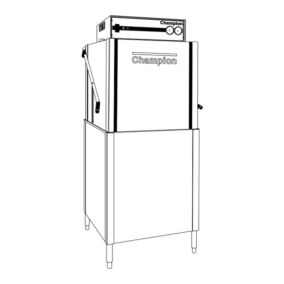
Door-Type
Dishwasher
Model
D-HBM3
High Temperature
with Built-in Booster
D-H1M3
High Temperature
D-LFM3
Low Temperature
Machine Serial No.
112428
P/N
Manual
2674 N. Service Road
Jordan Station, Ontario, Canada L0R 1S0
905/562-4195
Rev. A
Fax: 905/562-4618
Advertisement
Table of Contents
Troubleshooting

Related Manuals for Champion D-HBM3


Summary of Contents for Champion D-HBM3
- Page 1 D-LFM3 Low Temperature Machine Serial No. 112428 June, 1998 Manual Rev. A P.O. Box 4149 2674 N. Service Road Winston-Salem, North Carolina 27115-4149 Jordan Station, Ontario, Canada L0R 1S0 336/661-1556 Fax: 336/661-1660 905/562-4195 Fax: 905/562-4618 Email: champion@championindustries.com Champion Industries, Inc.
- Page 2 Champion Parts Distributor ___________________________________ Phone ______________ ______________________________________________________________________________ Champion Service Agency ____________________________________ Phone ______________ ______________________________________________________________________________ Champion Industries Service: 1 (800) 858-4477 Champion Service Fax: 1 (336) 661-1660 In Canada: Champion Service: 1 (800) 263-5798 Canada Service Fax: 1 (905) 562-4618 We strongly recommend that you fax your orders.
- Page 3 REVISIONS Revision History Revision Revised Serial Number Comments Date Pages Effectivity 10/6/97 90343 Issue manual with replacement parts lists 4/23/98 91586 Redesigned overflow lift arm P/N 112469 order P/N’s 112469-S and 322218 for machines built prior to S/N 91586...
-
Page 4: Table Of Contents
CONTENTS CONTENTS Page WARRANTY..........................5 INTRODUCTION ......................... 6 GENERAL ............................ 7 Model Numbers ........................7 Standard Equipment........................ 7 Options ............................ 7 Accessories ..........................7 Electrical Power Requirements....................8 INSTALLATION........................... 9 Unpacking ..........................9 Changing from Straight-through to Corner Operation ............9 Electrical Connections ...................... - Page 5 CONTENTS CONTENTS Page TROUBLESHOOTING......................... 20 BASIC SERVICE .......................... 22 Electrical Service ........................22 Fuses ..........................23 Motor Overloads....................... 23 Timers..........................24 Timed Fill/Low Water Tank Heat Protection ..............25 Heater Element Wiring..................... 26 Motor Connections ......................27 Mechanical Service......................... 28 Pump Seal Replacement....................
- Page 6 CONTENTS LIST OF FIGURES (cont’d) Figure 25— Track Assembly ....................... 36 Figure 26 — Wash/Rinse Spray Piping ..................38 Figure 27 — Wash/Rinse Spray Arms ..................40 Figure 28 — Drain Assembly and Scrap Screens ................ 42 Figure 29 — Wash Tank Heat, Thermostats, and Float Switch............ 44 Figure 30 —...
-
Page 7: Warranty
If a defect in workmanship or material is found to exist within the warranty period, Champion, at its election, will either repair or replace the defective machine or accept return of the machine for full credit; provided, however, as to glasswashers, Champion’s obligation with respect to labor associated with any repairs shall end... -
Page 8: Introduction
Replacement parts may be ordered from your Champion authorized parts distributor or from your Champion authorized service agency. When ordering parts, please supply the model number, serial number, voltage and phase of your machine, the part number, part description and... -
Page 9: General
GENERAL GENERAL This manual covers the Champion door type dishwashing machine. These machines are fully automatic and come equipped with a 1-HP pump motor. The D-series dishwasher is available in the following models: Model Numbers D-H1, D-HB, D-LF The D-H1 model is a high temperature (180°F/82°C rinse) sanitizing model without booster. -
Page 10: Electrical Power Requirements
GENERAL Electrical Power Requirements for Electric Heat / Electric Booster Model Voltage Booster Rise Machine Power Requirement (D-HB Only) Full Load Amps (125% Service Factor) D-H1/LF 115/60/1 — 48 Amps 60 Amps D-H1/LF 208/60/1 — 23 Amps 29 Amps D-H1/LF 220/60/1 —... -
Page 11: Installation
INSTALLATION INSTALLATION Unpacking CAUTION: Care should be taken when lifting the machine to prevent damage. Immediately after unpacking the machine, inspect for any shipping damage. If damage is found, save the packing material and contact the carrier immediately. Remove the dishwasher from the skid. Adjust the feet if required, then move the machine to its permanent location. -
Page 12: Electrical Connections
INSTALLATION Changing from Straight-through to Corner Operation (cont’d) Refer to Fig. 2 and perform the steps below. Remove the front rack guide (A). Discard the square spacers. Move front rack guide (A) to the left side of the rack tracks. (See Fig. 2b) Use existing hardware. -
Page 13: Plumbing Connections
INSTALLATION Electrical Connections (cont’d) A knock-out is provided at the rear of the top mounted control cabinet for the electrical service connection. A single source electrical connection has been provided. A fused disconnect switch or circuit breaker (supplied by others) is required to protect each power supply circuit. -
Page 14: Drain Connections
A PRV is standard equipment on Model D-HB. A PRV is not standard equipment on Models D-H1 and D-LF. The PRV may be obtained locally or direct from Champion. Drain Connections Refer to Fig. 5 for the location of the machine drain. -
Page 15: Chemical Connections
INSTALLATION Chemical Connections NOTE: Consult a qualified chemical supplier for your chemical needs. Models D-HB, D-H1 and D-LF Refer to Fig. 6 Labeled chemical signal connection points are provided inside the control cabinet for chemical dispensing equipment (supplied by others). Signal connection points include: •... -
Page 16: Rinse Aid/Sanitizer
INSTALLATION Chemical Connections (cont’d) Detergent (cont’d) Detergent may be added manually if dishwasher is not equipped with dispensing equipment. Consult your chemical supplier for recommended amounts. Rinse Aid/Sanitizer Model D-HB and D-H1 Refer to Fig. 8 A rinse aid injection point is provided via a 1/4" NPT plug located in the final rinse piping. The plug is located in a cross fitting on the outlet side of the vacuum breaker. -
Page 17: Figure 9 - Rinse Aid/Sanitizer Injection Points (D-Lf)
INSTALLATION Chemical Connections (cont’d) Rinse Aid/Sanitizer (cont’d) Model D-LF Refer to Fig. 9 A rinse aid injection point is provided via a 1/4" NPT plug located in the final rinse piping. The plug is located in a cross fitting on the outlet side of the vacuum breaker. The vacuum breaker is located behind the control cabinet at the top of the machine. -
Page 18: Initial Start-Up
8. Check pump motor rotation. Rotation is CW when viewed from rear of motor. 9. If machine checks okay, lift the drain lever assembly to drain machine. 10. Flip the power switch to OFF. Main power switch Pressure gauge circuit breaker Champion Green pushbutton start switch POWER WASH RINSE... -
Page 19: Model D-Hb, D-H1 And D-Lf
OPERATION OPERATION Model D-HB, D-H1 and D-LF Close the door and flip power switch ON Power light illuminates. Tank fills automatically and tank heat comes on. Monitor wash tank temperature gauge Wait for temperature reading to reach Min. 150°F/66°C (D-HB, D-H1 Only) Temperature reading must be Min. -
Page 20: Model D-Hb, D-H1 And D-Lf
MAINTENANCE MAINTENANCE Cleaning your machine is the best maintenance that you can provide. Components that are not regularly flushed and cleaned do not perform well. The Maintenance intervals shown in the following schedules are the minimum requirements necessary for the proper performance of your machine. Maintenance intervals should be shortened whenever your machine is faced with abnormal working conditions, hard water, or multiple shift operations. -
Page 21: Deliming
MAINTENANCE DELIMING Your dishwasher should be delimed regularly depending on the mineral content of your water. Inspect the machine interior for mineral deposits and use a deliming solution for the best cleaning results. NOTE: Consult your chemical supplier for an appropriate deliming solution. WARNING: Deliming solutions or other acids must not come in contact with household bleach (sodium hypochlorite) or any chemicals containing chlorine, iodine, bromine, or fluorine. -
Page 22: Operation Checks
MAINTENANCE OPERATION CHECKS • Daily Check temperature gauges for proper readings. Check pressure gauge for proper reading (D-H1, D-HB ONLY). Check for leaks. Check chemical supplies and refill as necessary. • Weekly Inspect all water lines for leaks. Clean all detergent residue from the exterior of the machine. Check the drains for leaks. - Page 23 TROUBLESHOOTING CONDITION CAUSE SOLUTION Any motor not running Overload protector tripped ....Reset overload in Control Box Defective motor........Contact your service agency Wash tank water temperature Incoming water temperature is low when in use at machine too low ......Raise temperature to: 140°F/60°C for D-HB and D-LF, 180°F/82°C for D-H1 Defective thermometer......Check or replace...
-
Page 24: Basic Service
Troubleshooting Schematics Champion places an electrical schematic in the control cabinet of every machine before it is shipped. Schematics are included at the back of this manual as well. Be aware that these schematics include options that may not apply to your machine. Options are enclosed in dashed lines with the words (IF USED) next to them on the schematic. -
Page 25: Fuses
BASIC SERVICE ELECTRICAL SERVICE (cont’d) Fuses — Refer to Fig. 12. There are two fuse blocks, located in the center of the main control cabinet. The (A) fuses protect the main control transformer. The (B) fuses protect the wash tank heater circuit. Fuses are marked FU on the electrical schematic. -
Page 26: Timers
BASIC SERVICE D-HB, D-H1, and D-LF models have two timers located in the top mounted main control cabinet. These timers are not adjustable. The timer chart is shown in Fig. 15. Cycle Timer — Refer to Fig. 14. The cycle timer controls the dishwasher’s 60-second operation. -
Page 27: Timed Fill/Low Water Tank Heat Protection
BASIC SERVICE Models D-HB, D-H1, and D-LF use a float switch and fill timer to control tank fill and tank heat. For Model D-HB only, the built-in booster heat circuit is also controlled by the float switch. Operation: When dishwasher main power switch is turned on (wash tank empty), the fill timer runs for a minimum of 90 seconds to fill the tank. -
Page 28: Heater Element Wiring
BASIC SERVICE ELECTRICAL SERVICE (cont’d) Heater Element Wiring – Booster Tank and Wash Tank Heater Elements Refer to the illustrations and follow the steps below to properly install terminal jumpers and to make line power connections to a replacement element. Step 1. -
Page 29: Motor Connections
BASIC SERVICE ELECTRICAL SERVICE (cont’d) Motor Connections — 1. Models D-HB, D-H1, and D-LF are available in either single phase or 3 phase voltages. 2. Motor rotation was set at the factory. For three phase machines, reversing the motor direction is done in the control cabinet by reversing the wires L1 and L2 on the disconnect side of the main electrical connection block. -
Page 30: Mechanical Service
BASIC SERVICE MECHANICAL SERVICE Pump Seal Replacement 1. Disconnect the power to the machine at the main breaker panel or fuse box. 2. Drain the machine. 3. Remove the front and side panels. 4. Remove drain plug on the pump volute and drain the pump. 5. -
Page 31: Replacement Parts List
REPLACEMENT PARTS REPLACEMENT PARTS... -
Page 32: Figure 22 - Doors, Panels And Gauges
REPLACEMENT PARTS Figure 22 – D-HB/D-H1/D-LF Doors, Panels and Gauges... - Page 33 REPLACEMENT PARTS D-HB/D-H1/D-LF DOORS, PANELS AND GAUGES Fig. 22 Part Item No. Part Description Qty. 0709405 DOOR, SIDE RIGHT ....... . . 0709402 FRONT DOOR, DOOR MACH.
-
Page 34: Figure 23 - Door Guides, Stops, And Lift Bracket
REPLACEMENT PARTS Figure 23 – D-HB/D-H1/D-LF Door Guides, Stops, and Lift Bracket... - Page 35 REPLACEMENT PARTS D-HB/D-H1/D-LF DOOR GUIDES, STOPS, AND LIFT BRACKET Fig. 23 Part Item No. Part Description Qty. 108053 PLUG, CORNERPOST ....... . 107966 NUT, GRIP 10-32 W/INSERT .
-
Page 36: Figure 24 - Door Handle And Spring Assembly
REPLACEMENT PARTS Figure 24 – D-HB/D-H1/D-LF Door Handle and Spring Assembly... - Page 37 REPLACEMENT PARTS D-HB/D-H1/D-LF DOOR HANDLE AND SPRING ASSEMBLY Fig. 24 Part Item No. Part Description Qty. 0509168 BOLT 5/16-18 X 11 HEX HEAD......108066 SPRING, EXTENSION .
-
Page 38: Figure 25- Track Assembly
REPLACEMENT PARTS Figure 25 – D-HB/D-H1/D-LF Track Assembly... - Page 39 REPLACEMENT PARTS D-HB/D-H1/D-LF TRACK ASSEMBLY Fig. 25 Part Item No. Part Description Qty. 0309469 Guide, right hand ........0309472 Track, rear .
-
Page 40: Figure 26 - Wash/Rinse Spray Piping
REPLACEMENT PARTS Figure 26 – D-HB/D-H1/D-LF Wash/Rinse Spray Piping... - Page 41 REPLACEMENT PARTS D-HB/D-H1/D-LF WASH/RINSE SPRAY PIPING Fig. 26 Part Item No. Part Description Qty. 0309444 RINSE TUBE ........0509181 FITTING, STRAIGHT COMPRESSION.
-
Page 42: Figure 27 - Wash/Rinse Spray Arms
REPLACEMENT PARTS Figure 27– D-HB/D-H1/D-LF Wash/Rinse Spray Arms... - Page 43 REPLACEMENT PARTS D-HB/D-H1/D-LF WASH/RINSE SPRAY ARMS Fig. 27 Part Item No. Part Description Qty. 0507443 SPINDLE, RINSE ARM ....... . 0508376 NOZZLE, RINSE ARM (DHB, D-H1 only).
-
Page 44: Figure 28 - Drain Assembly And Scrap Screens
REPLACEMENT PARTS Figure 28 – D-HB/D-H1/D-LF Drain Assembly and Scrap Screens... - Page 45 REPLACEMENT PARTS D-HB/D-H1/D-LF DRAIN ASSEMBLY AND SCRAP SCREENS Fig. 28 Part Item No. Part Description Qty. 110427 SEAL OVERFLOW TUBE ......112468 OVERFLOW WELDMENT.
-
Page 46: Figure 29 - Wash Tank Heat, Thermostats, And Float Switch
REPLACEMENT PARTS Figure 29 – D-HB/D-H1/D-LF Wash Tank Heat, Thermostats, and Float Switch... -
Page 47: Figure 18 - Float Switch
REPLACEMENT PARTS D-HB/D-H1/D-LF WASH TANK HEAT, THERMOSTATS AND FLOAT SWITCH Fig. 29 Part Item No. Part Description Qty. 107440 THERMOMETER 8 FT....... . . 109069 THERMOSTAT W/CAP 110-220%F . -
Page 48: Figure 30 - Electric Booster And Thermostat (D-Hb Only)
REPLACEMENT PARTS Figure 30 – D-HB Only Electric Booster and Thermostat... - Page 49 REPLACEMENT PARTS D-HB ONLY ELECTRIC BOOSTER AND THERMOSTAT Fig. 30 Part Item No. Part Description Qty. 100740 BOLT 5/16-18 X 1 HEX HEAD ......102376 WASHER, FLAT 5/16 X 3/4 X 1/16 .
-
Page 50: Figure 31 - D-Hb Lower Fill Piping Assembly
REPLACEMENT PARTS TO UPPER PIPING CUSTOMER WATER INLET Figure 31 – D-HB ONLY Lower Fill Piping Assembly... - Page 51 REPLACEMENT PARTS D-HB ONLY LOWER FILL PIPING ASSEMBLY Fig. 31 Part Item No. Part Description Qty. 112387 LINE STRAINER/PRV COMBO......102444 STREET ELL 3/4"...
-
Page 52: Figure 32 - D-Hb, D-H1 Upper Fill Piping Assembly
REPLACEMENT PARTS FINAL RINSE THERMOMETER BULB WATER IN FROM LOWER PIPING Figure 32 – D-HB/D-H1 Upper Fill Piping Assembly... - Page 53 REPLACEMENT PARTS D-HB/D-H1 UPPER FILL PIPING ASSEMBLY Fig. 32 Part Item No. Part Description Qty. 102438 ELBOW, STREET 1/2" NPT X 90 BRASS ....102549 UNION 1/2"...
-
Page 54: Figure 33 - D-H1/D-Lf Lower Fill Piping Assembly
REPLACEMENT PARTS TO UPPER PIPING CUSTOMER WATER IN Figure 33 – D-H1/D-LF Lower Fill Piping Assembly... - Page 55 REPLACEMENT PARTS D-H1/D-LF LOWER FILL PIPING ASSEMBLY Fig. 33 Part Item No. Part Description Qty. 102444 STREET ELL 3/4" NPT BRASS ......0309340 PLUMBING SUPPORT BRACKET .
-
Page 56: Figure 34 - D-Lf Upper Fill Piping Assembly
REPLACEMENT PARTS FINAL RINSE THERMOMETER BULB WATER IN FROM LOWER PIPING Figure 34 – D-LF Upper Fill Piping Assembly... - Page 57 REPLACEMENT PARTS D-LF UPPER FILL PIPING ASSEMBLY Fig. 34 Part Item No. Part Description Qty. 102438 ELBOW, STREET 1/2" NPT X 90 BRASS ....102549 UNION 1/2"...
-
Page 58: Figure 35 - Pump Assembly
REPLACEMENT PARTS Figure 35 – D-HB/D-H1/D-LF Pump Assembly... - Page 59 REPLACEMENT PARTS D-HB/D-H1/D-LF PUMP ASSEMBLY Fig. 35 Part Item No. Part Description Qty. 308005 STRAINER ......... . 107966 NUT, GRIP 10-32 W/NYLON INSERT .
-
Page 60: Figure 36 - Control Cabinet
CONTACTOR WASH MOTOR OVERLOAD TRANSFORMER LINE V: 120V TRANSFORMER 120V:24V Champion POWER WASH RINSE START CYCLE W A R N I N G ! T U R N O F F P O W E R B E F O R E S E R V I C I N G M A C H I N E Figure 36 –... - Page 61 REPLACEMENT PARTS D-HB/D-H1/D-LF CONTROL CABINET Fig. 36 Part Item No. Part Description Qty. 100292 Terminal block, 1 Phase ....... . . 106010 Terminal block, 3 Phase .
-
Page 62: Figure 37 - Dishracks And Prv
REPLACEMENT PARTS Figure 37 – D-HB/D-H1/D-LF Dishracks and PRV... - Page 63 REPLACEMENT PARTS D-HB/D-H1/D-LF DISHRACKS AND PRV Fig. 37 Part Item No. Part Description Qty. 101273 RACK (FLAT BOTTOM) ....... 101285 RACK (PEG) .
- Page 64 REPLACEMENT PARTS THIS PAGE INTENTIONALLY LEFT BLANK...
- Page 65 ELECTRICAL SCHEMATICS ELECTRICAL SCHEMATICS...
-
Page 66: Electrical Schematics
ELECTRICAL SCHEMATICS TO CUSTOMERS DISCONNECT SWITCH PER LOCAL ELECTRICAL CODE 1MOL 1MTR 208V 115V 480V 230V 380V 415V 575V WHITE 1HTR TANK HEAT DELTA CONNECTION TANK HEAT WYE 208/230/480/575 VAC CONNECTION 380/415 VAC 24V. HWCO 2HTR BOOSTER HEAT DELTA CONNECTION BOOSTER HEAT 208/230 VAC 1MOL... -
Page 67: Figure 39 - Electrical Schematic D-Hb/D-H1/D-Lf, 1 Phase
ELECTRICAL SCHEMATICS TO CUSTOMERS DISCONNECT SWITCH PER LOCAL ELECTRICAL CODE NOT REQUIRED ON 115V MODELS 1MOL 1MTR 208V 115V 230V WHITE 1HTR TANK HEAT CONNECTION 115/208/230/VAC 24V. HWCO BOOSTER HEATER CONNECTION 1MOL 208/230/VAC BOOSTER STEAM VALVE CIRCUIT BREAKER DET. SIG. HOLD IN RELAY LOW WATER SHUT OFF RELAY RINSE AID/...
Need help?
Do you have a question about the D-HBM3 and is the answer not in the manual?
Questions and answers