Champion Genesis DH5000T Series Installation And Operation Manual
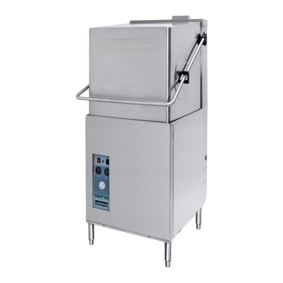
Tall hood-type high temperature dishwasher
Hide thumbs
Also See for Genesis DH5000T Series:
Table of Contents
Advertisement
Installation/Operation Manual with Service Re
LISTED
3765 Champion Boulevard
Winston-Salem, NC 27105
336/661-1556 Fax: 336/661-1660
Toll-free: 800/ 858-4477
2674 N. Service Road, Jordan Station
Ontario, Canada L0R 1S0
905/562-4195 Fax: 905/562-4618
Toll-free: 800/ 263-5798
placement Parts
Tall Hood-type
High Temperature
Dishwasher
Model: DH5000T Series
Standard Model:
Hot water sanitizing machine w/fresh
water rinse and built-in stainless steel
electric booster
Also available with:
Direct Vent Option or
Condensate Removal Option
Issue Date: 1.31.13
Manual P/N
115105 rev. A
For machines beginning with S/N D120810203 and above
Machine Serial No.
Printed in the USA
Advertisement
Chapters
Table of Contents

Related Manuals for Champion Genesis DH5000T Series


Summary of Contents for Champion Genesis DH5000T Series
- Page 1 Parts Installation/Operation Manual with Service Re Tall Hood-type High Temperature Dishwasher Model: DH5000T Series Standard Model: Hot water sanitizing machine w/fresh water rinse and built-in stainless steel electric booster Also available with: Direct Vent Option or Condensate Removal Option Machine Serial No.
- Page 2 The USGBC and the CaGBC Member Logos are trademarks owned by the U.S. Green Building Council and The Canadian Green Building Council, respectively, and are used by permission. The logos signify only that Champion Industries is a USGBC and a CaGBC member; USGBC and CaGBC do not review, certify nor endorse the products or services offered by its members.
- Page 3 REGISTER YOUR PRODUCT ONLINE Make sure you are connected to the internet then enter the address below. In the U.S.A http://www.championindustries.com/register In Canada http://www.championindustries.com/canada/register...
-
Page 4: Product Registration
PRODUCT REGISTRATION BY FAX COMPLETE THIS FORM AND FAX TO: (336) 661-1660 in the USA 1-(800) 204-0109 in Canada PRODUCT REGISTRATION CARD Model Serial # Date of Installation: Company Name: Address: (Street) Province Postal Code Telephone #: ( Contact: Installation Company: Address: Telephone #: Contact:... -
Page 5: Revision History
Revision History Revision History A revision might be a part number change, a new instruction, or other information that was not available at print time. We reserve the right to make changes to these instructions without notice and without incurring any liability by making the changes. Equipment owners may request a revised manual, at no charge, by calling 1 (800) 858-4477 in the USA or by calling 1 (800) 263-5798 in Canada. -
Page 6: Limited Warranty
If a defect in workmanship or material is found to exist within the warranty period, Champion, at its election, will either repair or replace the defective machine or accept return of the machine for full credit; provided;... -
Page 7: Table Of Contents
Table of Contents Table of Contents DH5000T Series Tall Hood-type Dishwasher Revision History ......................i Limited Warranty ......................ii Model Descriptions ......................iv ..................Installation Receiving .................... 1 Placement .................... 1 Installing Condensate Removal or Direct Vent Options ......2 Converting Straight-through Operation to Corner Operation ....3 Electrical Connections ................ -
Page 8: Model Descriptions
Model Description Model Description DH5000T Series High temperature hot water sanitizing dishwasher with built-in 40-70°F/22-82°C rise booster heater. 208-240V/60/1 & 3, 460-480V/60/3 Field convertible for straight-through or corner operation Self-draining pump Automatic start Fresh water rinse Standard Cycle: 60 second or 90 second total cycle time... -
Page 9: Installation
Installation Receiving Inspect the outside of the dishwasher carton for signs of damage. Remove the carton and inspect the dishwasher for damage. Check for any options or accessories that may have shipped with your dishwasher. Turn to the front of this manual and follow the instructions to register your product online or by fax. - Page 10 Installation Placement (continued) Dishwashers are shipped from the factory for straight-through operation. Refer to page 4 to convert the dishwasher from straight-through to corner operation. Control Panel Straight-through Operation Shown The dishwasher has 4 adjustable feet for leveling. Level the dishwasher front-to-back and side-to-side. Adjustable Feet Dish Table Connections NOTE:...
-
Page 11: Installing Condensate Removal Or Direct Vent Options
Installation Installing Condensate Removal or Direct Vent Options NOTE Complete installation instructions are located at the end of this service manual. The dishwasher may be equipped with either a Condensate Removal Option or a Direct Vent Option. These options ship separately from the dishwasher in their own containers. Separate instructions are also included attached to the front of the dishwasher. -
Page 12: Converting Straight-Through Operation To Corner Operation
Installation Converting Straight-through Operation to Corner Operation ! ATTENTION ! A straight-through machine can be converted to a corner configuration in the field. Refer to the illustration below and on the next two pages to convert a straight-through operation machine to a corner operation machine. To convert the dishwasher: Place the dishwasher as shown below so the control panel faces into the room and is accessible to the operator. - Page 13 Installation Converting Straight-through Operation to Corner Operation (continued) ! ATTENTION ! A straight-through machine can be converted to a corner configuration in the field. 1-7/8" 5⅛" [48] [130] MIN. MIN. Controls must be accessible. CORNER CONFIGURATION...
- Page 14 Installation Converting Straight-through Operation to Corner Operation (continued) ! ATTENTION ! The dish rack guides must be repositioned for corner operation. Follow the steps below to change the dish rack guides for corner operation. Step 1: Remove the rack guide (A); save the fasteners. Step 2: Move (A) and re-attach as shown in the illustration below.
-
Page 15: Electrical Connections
Installation Electrical Connections WARNING: Electrocution or serious injury may result when working on an energized circuit. Disconnect power at the main breaker or service disconnect switch before working on the circuit. Lock-out and tag the breaker to indicate that work is being performed on the circuit. - Page 16 Installation Electrical Connections Connecting Incoming Power Supply (continued) Connect the incoming power flexible conduit to the incoming conduit mounting bracket located on the rear of the dishwasher base making sure to leave 6 feet [2 m] of excess conduit and conductors to allow for servicing of the dishwasher. Route the power conductors through the 1-1/2"...
- Page 17 Blank Page This Page Intentionally Left Blank...
-
Page 18: Water Connections
Installation Water Connections for Standard Model and Direct Vent Option Model ! ATTENTION ! A qualified plumber must connect the water supply to the dishwasher in accordance with all local plumbing and sanitation codes and regulations. Improper installation will not be covered by the Limited Warranty. 1. - Page 19 Installation Water Connections for Condensate Removal Option Model The DH5000T dishwasher equipped with a Condensate Removal Option requires an incoming cold water supply only. COLD WATER — 3/4" NPT, 55-75°F/13-24°C maximum temperature, with a minimum incoming flowing pressure of 45 PSI measured at the dishwasher supply connection before adjusting operating pressure to 20/25 PSI flowing pressure.
-
Page 20: Drain Connection
Installation Drain Connection - All Models The drain water connection is a 2" slip-fit hose connection and is located at the center-rear of the machine base. It is a gravity drain. The dishwasher drain is 2" O.D. hose connection. An optional drain water tempering kit is available (consult the factory). -
Page 21: Standard Dh5000T Vent Fan Control
Installation Standard Model and Direct Vent Option Model Chemical Dispensing Provisions ! ATTENTION ! Consult a qualified chemical supplier for chemical supplies and chemical dispensing equipment. Provisions for chemical suppliers to connect their chemical dispensing systems are provided on the dishwasher and include: A 1/8"... -
Page 22: Chemical Dispensing Provisions
Installation Chemical Dispensing Provisions - Condensate Removal Option Model Only ! ATTENTION ! Consult a qualified chemical supplier for chemical supplies and chemical dispensing equipment. Provisions for chemical suppliers to connect their chemical dispensing systems are provided on the dishwasher and include: A 1/8"... -
Page 23: Initial Start-Up
Initial Start-up Initial Start-up Check List Remove any protective film from dishwasher. Check the interior for foreign material. Make sure the dishwasher is permanently located. Make sure all utility connections are complete. Make sure the chemical supply containers are full. Make sure the pump suction screen is in place. -
Page 24: Operation
Operation Control Panel Description The control panel is located on the front left side of the lower panel. The controls include: A - ON/OFF DRAIN power switch. Turns power on and off and initiates a drain cycle when the switch is placed in the Off/Drain position. B - CYCLE green indicator light. -
Page 25: Digital Temperature Display Description
Operation Digital Temperature Display Description The wash tank and the final rinse temperatures are numerically displayed and a colored bar around the numbers creates a visual indication of the temperature. When the color of the bar is yellow then the water temperature is below the minimum temperature required to operate the machine. -
Page 26: Standard Wash Cycle Operation
Operation Standard Wash Cycle Operation Follow the instructions below to operate the dishwasher in a Standard Wash Cycle. A Rinse Sentry feature holds the dishwasher in a wash cycle if the booster heater temperature is below 180ºF/82ºC. Turn the main power on at the main circuit breaker. Make sure the spray arms and the scrap screens are in place. - Page 27 Operation Standard Wash Cycle Operation (continued) Wait up to 10 minutes for the WASH temperature display to indicate a minimum of 150ºF/66ºC. NOTE: The final rinse display may indicate a temperature that is less than a minimum of 180ºF/82ºC during the wash cycle.
- Page 28 Operation Standard Wash Cycle Operation (continued) 12. The wash cycle time runs for the selected time. 13. Opening the hood when the dishwasher is in-cycle will pause the cycle. The cycle will resume automatically when the dishwasher hood is closed. 14.
-
Page 29: Automatic Drain Cycle
Operation Automatic Drain Cycle The dishwasher can be drained automatically when the dishwasher has completed a normal wash cycle or whenever the dishwasher is idle. To drain the dishwasher: Push the dishwasher power Switch down to the OFF/DRAIN position. The illuminated power switch will go out. -
Page 30: Heavy Duty Wash Cycle Operation
Operation Heavy Duty Wash Cycle Operation ! VERY IMPORTANT ! THE HEAVY DUTY CYCLE MAY BE SELECTED BEFORE OR AFTER THE POWER SWITCH IS PRESSED; BUT, THE CYCLE SELECTOR SWITCH WILL NOT CHANGE THE CYCLE FROM 4 MINUTES TO 6 MINUTES OR VICE VERSA WHILE THE DISHWASHER IS ALREADY IN CYCLE. Follow the instructions below to operate the dishwasher in the Heavy Duty Wash Cycle. - Page 31 Operation Heavy Duty Wash Cycle Operation (continued) Check the pressure gauge as the machine fills and make sure the incoming water flowing pressure is between 20-22 psi. Wait up to 10 minutes for the WASH temperature display to indicate a minimum of 150ºF/66ºC.
- Page 32 Operation Heavy Duty Wash Cycle Operation (continued) 11. Close the hood, the green CYCLE light will illuminate and the heavy duty wash cycle will begin automatically. The wash cycle time runs for the selected time. 1 5 0 1 7 0 WASH RINSE 150°F...
-
Page 33: Rinse Sentry Operation Mode
Operation Rinse Sentry Operation Mode The final rinse water temperature must be a minimum of 180ºF/82ºC during the final rinse cycle to ensure all wares are sanitized. If for any reason, the hot water temperature in the booster tank cannot provide this temperature, the dishwasher will enter a Rinse Sentry Mode of operation and extend the cycle time. -
Page 34: Cleaning And Maintenance
Cleaning and Maintenance Cleaning After Each Meal Period or every 8 Hours of Operation. Push the lighted power switch DOWN to the OFF/DRAIN position. The power switch light will go out and the automatic drain cycle will operate for 10 minutes. The cycle light is not illuminated during the drain cycle. - Page 35 Cleaning and Maintenance Cleaning At the End of the Day Perform Steps 1-10 on the previous page. Remove the upper and lower rinse and wash spray arms. The spray arms are interchangeable. Unscrew the upper and lower rinse arm spindles (A). Remove the rinse arm assemblies Clean the final rinse arm nozzles using a small paper clip (B).
-
Page 36: De-Liming
Cleaning and Maintenance De-liming Minerals accumulate on the interior surfaces of the dishwasher. The deposits have a white haze and, in cases of heavy accumulation, may appear as a granular solid. The generic name for mineral deposits is lime. The removal of lime deposits is called de-liming. Your dishwasher should be de-limed regularly;... -
Page 37: Maintenance
Cleaning and Maintenance Maintenance Daily Maintenance Check all of the wash arm and rinse arm spray jets and clean as necessary. Make sure the water supply is on and the drain is not clogged. Check the temperature displays to ensure they are operating. Make sure the dish racks are in good condition. -
Page 38: Troubleshooting
Troubleshooting Follow the troubleshooting guide below in the event your dishwasher does not operate as expected. Condition Cause Solution Dishwasher will not run. Hood not closed. Close Hood completely. Main power OFF. Check breaker on panel. Dishwasher OFF. Turn dishwasher ON. Low or no water. -
Page 39: Service Replacement Parts
Service Replacement Parts Service Replacement Parts Illustrations Page Wash Pump/Motor Assembly ........................ Fill Piping Assembly without Booster - Standard Model and Direct Vent Option Model Only ....Fill Piping Assembly with Booster - Standard Model and Direct Vent Option Model ......Fill Piping Assembly with Booster - Condensate Removal Option Model Only ........ -
Page 40: Wash Pump/Motor Assembly
Wash Pump/Motor Assembly... - Page 41 Wash Pump/Motor Assembly Item Part Description Qty. 114134 SLINGER, WATER 114135 114136 SCREW 114137 PLATE, BACKING, C/W CAPACITOR BRKT. 110285 GASKET, PUMP 114139 SEAL, PUMP 114140 WASHER 114141 IMPELLER 114142 WASHER 114143 WASHER, LOCK 114144 NUT, IMPELLER (LH THREADS) 114145 HOUSING, PUMP 114322 CAPACITOR 15μF 240VAC...
-
Page 42: Fill Piping Assembly Without Booster - Standard Model And Direct Vent Option Model Only
Fill Piping Assembly without Booster - Standard Model and Direct Vent Option Model Only... - Page 43 Fill Piping Assembly without Booster - Standard Model and Direct Vent Option Model Only Item Part Description Qty. 102392 BUSHING, REDUCING, 3/4" NPT X 1/2" NPT BRASS 102438 ELBOW, STREET 1/2" NPT X 90° BRASS 111437 VALVE, SOLENOID 3/4" NPT HW 114839 KIT, REPAIR VALVE 3/4"...
-
Page 44: Fill Piping Assembly With Booster - Standard Model And Direct Vent Option Model
Fill Piping Assembly with Booster - Standard Model and Direct Vent Option Model Only... - Page 45 Fill Piping Assembly with Booster - Standard Model and Direct Vent Option Model Only Item Part Description Qty. 102392 BUSHING, REDUCING, 3/4" NPT X 1/2" NPT BRASS 102438 ELBOW, STREET 1/2" NPT X 90° BRASS 111437 VALVE, SOLENOID 3/4" NPT HW 114839 KIT, REPAIR VALVE 3/4"...
-
Page 46: Fill Piping Assembly With Booster - Condensate Removal Option Model Only
Fill Piping Assembly with Booster - Condensate Removal Option Model Only... - Page 47 Fill Piping Assembly with Booster - Condensate Removal Option Model Only Item Part Description Qty. 102392 BUSHING, REDUCING, 3/4" NPT X 1/2" NPT BRASS 102651 NIPPLE, 3/4" NPT X 2" LG. BRASS 107550 VALVE, PRESSURE REGULATING 3/4" NPT BRONZE 110768 STRAINER, LINE 3/4"...
-
Page 48: Booster Assembly - All Models And Options
Booster Assembly - All Models and Options... - Page 49 Booster Assembly - All Models and Options Item Part Description Qty. 419002 HOSE ASSY. 1/2" ID, X 16" LG. FLARE JIC 115101 COUPLING, MALE 1/2" NPT X 1/2" 37° FLARE BRASS 100171 BUSHING, REDUCING FACE 3/4" NPT X 1/2" NPT BRASS 102438 ELBOW, STREET 1/2"...
-
Page 50: Control Panel Assembly
Control Panel Assembly... - Page 51 ELBOW, 1/4" OD X 1/8" NPT FEMALE, PLASTIC 109812 GAUGE, PRESSURE, 0-60 PSI 107928 TUBING, 1/4" NATURAL P44 6 FT 115090 DECAL, FRONT PANEL, DH5000T (Champion Only) 115090-R DECAL, FRONT PANEL, DH5000T (Russell Only) 114489 GAUGE, DIGITAL TEMPERATURE DISPLAY 114559 SUPPORT, PRINTED CIRCUIT BOARD...
-
Page 52: Control Cabinet And Input Terminal Block Assembly
Control Cabinet and Input Terminal Block Assembly... - Page 53 Control Cabinet and Input Terminal Block Assembly Item Part Description Qty. 334232 INNER PANEL, CONTROL CABINET 107964 BUSHING, SNAP 7/8" D-FLAT B500355 CONNECTOR, STRAIN RELIEF, CORD 1/2" 103310 GROUND LUG 100095 SCREW, ROUND HEAD, 10-32 X 3/8" SST 100100 SCREW, ROUND HEAD, 8-32 X 1/4" SST 114898 TRANSFORMER, 120:24V, 50/60HZ, 20VA 113314...
-
Page 54: Wash/Rinse Spray Piping - Standard Model And Direct Vent Option Model
Wash/Rinse Spray Piping - Standard Model and Direct Vent Option Model See page 50 for spray arms... - Page 55 Wash/Rinse Spray Piping - Standard Model and Direct Vent Option Model Item Part Description Qty. 100500 BREAKER, VACUUM 1/2" NPT BRONZE 900836 KIT, REPAIR VACUUM BREAKER 1/2" 100209 NIPPLE, 1/2" NPT X CLOSE BRASS 102514 TEE, 1/2" NPT BRASS 114435 THERMISTER, 10KΩ, 36" LEAD 102388 BUSHING, REDUCING 1/2"...
-
Page 56: Wash/Rinse Spray Piping - Condensate Removal Option Model
Wash/Rinse Spray Piping - Condensate Removal Option Model See page 50 for spray arms Refer to Pages 64-65 for the Condensate Removal Option - Shroud, Fan, and Coil Assembly Parts List... - Page 57 Wash/Rinse Spray Piping - Condensate Removal Option Model Item Part Description Qty. 101261 ELBOW, STREET 1/4" NPT X 90° BRASS 102388 BUSHING, REDUCING 1/2" NPT X 1/4" NPT BRASS 107065 ADAPTER, 1/4" OD X 1/4"MPT PLASTIC 107928 TUBING, 1/4" NATURAL P44 10 FT 102514 TEE, 1/2"...
-
Page 58: Wash And Rinse Spray Arm Assemblies
Wash and Rinse Spray Arm Assemblies... - Page 59 Wash and Rinse Spray Arm Assemblies Item Part Description Qty. 207096 WASHARM, BEARING 114858 WASHARM, WELDMENT 0507443 SPINDLE, RINSE ARM 114556 NUT, SPINDLE 114943 RINSE ARM, TRI-ARM WELDMENT 114861 ENDCAP, HEADLESS, 7/16-20 SST 113514 BEARING, RINSE ARM 109835 SCREW, #8 X 1/2" SELF-TAPPING PAN HEAD, PHILLIPS 900953 RINSE ARM ASSEMBLY, COMPLETE (includes items 5 and 7)
-
Page 60: Wash Tank Heat, Drain, Screens, And Hoses
Wash Tank Heat, Drain, Screens, and Hoses See heater detail below Heater Detail Thermostat Detail... - Page 61 Wash Tank Heat, Drain, Screens, and Hoses Item Part Description Qty. 109034 GASKET, 1/2" PLUG 108417 NUT, 1/2" NPT PLASTIC 108418 PLUG, 1/2" NPT PLASTIC 114386 WASHER, RUBBER 13/16" X 1-1/4" X 1/8" 333021 SCREEN, PUMP SUCTION 332544 SUPPORT, FILLER SCREEN 305164 SCREEN, SCRAP 111092...
-
Page 62: Track And Panel Assemblies
Track and Panel Assemblies... - Page 63 Track and Panel Assemblies Item Part Description Qty. 100754 SCREW, FLAT HD., 10-32 X 1/2" SST 332025 TUBE, CROSS TRACK 332021 TRACK, REAR 106486 WASHER, LOCK #10 SPLIT, SST 104985 NUT, PLAIN, 10-32 SST 332023 TRACK, RAIL ADJUST 333086 TRACK, FRONT 100214 SCREW, TRUSS HD., 1/4-20 X 3/4"...
-
Page 64: Hood And Hood Handle Assemblies
Hood and Hood Handle Assemblies... - Page 65 Hood and Hood Handle Assemblies Item Part Description Qty. 115089 HANDLE, HOOD 107397 BLOCK, SPRING HOOK 114865 SCREW, 1/4-20 X 1" FLAT WIDE HEAD 107399 SUPPORT, PIVOT BLOCK 106026 WASHER, FLAT 1/4" SST 100003 NUT, PLAIN 1/4-20 SST 107437 BOLT, M6 X 45MM HEX HEAD H191014 BLOCK, UPPER PIVOT DOOR HANDLE H191013...
-
Page 66: Back Support And Hood Guide Assembly
Back Support and Hood Guide Assembly... - Page 67 Back Support and Hood Guide Assembly Item Part Description Qty. 334271 DUCT, EXHAUST WELDMENT 114904 GASKET, EXHAUST DUCT 100073 SCREW, TRUSS HEAD, 1/4-20 X 1/2" SST 334657 BRACKET STOP, HANDLE 334612 SUPPORT WELDMENT, BACK 100003 NUT, PLAIN 1/4-20 SST 114154 BOLT, CARRIAGE 1/4-20 X 1/2"...
-
Page 68: Condensate Removal Option And Direct Vent Option - Electrical Control Box
Condensate Removal Option and Direct Vent Option - Electrical Control Box Machine Mount Wall Mount 10 11 12 13... - Page 69 Condensate Removal Option and Direct Vent Option - Electrical Control Box Item Part Description Qty. 334463 BRACKET, ENCLOSURE MOUNT (MACHINE MOUNT) 100779 SCREW, 1/4-20 X 5/8" TRUSS HEAD SST 106026 WASHER, FLAT 1/4" SST 106482 WASHER, SPLIT LOCK 1/4" SST 100003 NUT, PLAIN 1/4-20 SST 114973...
-
Page 70: Direct Vent Option - Shroud And Exhaust Fan
Direct Vent Option - Shroud and Exhaust Fan The Optional Champion Supplied Vent Fan AIRFLOW is Sold Separately... - Page 71 Direct Vent Option - Shroud and Exhaust Fan Item Part Description Qty. 106481 NUT, ACORN PLAIN NUT, 1/4-20 SST 207116 RING, ANGLE 4" DUCT DIAMETER W/HOLES 334448 DIRECT VENT SHROUD WELDMENT 334451 DIRECT VENT SHROUD ENCLOSURE 100073 SCREW, 1/4-20 X 1/2" TRUSS HEAD, SST 114949 FAN, INLINE EXHAUST DUCT 6"...
-
Page 72: Condensate Removal Option - Shroud, Fan, And Coil
Condensate Removal Option - Shroud, Fan, and Coil Refer to Pages 48-49 for the Condensate Removal Option vacuum breaker piping Cold Water Supply In From Booster To Line Strainer To Rinse Arms Rinse Aid... - Page 73 Condensate Removal Option - Shroud, Fan, and Coil Item Part Description Qty. 334680 BOX WELDMENT, CONDENSATE REMOVAL 114988 SCREW, FILLISTER HEAD, 8-32 X 2" SST 114976 FAN, 85 CFM AXIAL, 85-265VAC 334552 PLENUM TOP, COIL 334475 SHROUD, COIL 114931 COIL ASSEMBLY 334374 PANEL, REAR CONDENSATE REMOVAL 102438...
-
Page 74: Drain Water Tempering Assembly
Drain Water Tempering Assembly... - Page 75 Drain Water Tempering Assembly Item Part Description Qty. 107564 SCREW, 6-32" X 1" TRUSS HD. SST 114662 TIMER, INFITEC 30 SECONDS 107340 CLAMP, HOSE M28 SST, GEAR-TYPE 332280 TEE, WELDMENT 1-3/8" X 1/2" BARB X 1-3/8" 105994 CLAMP, HOSE M10 SST GEAR-TYPE 107417 1/2"...
-
Page 76: Dish Racks, Line Strainer And Pressure Regulating Valve (Prv)
Dish Racks, Line Strainer, PRV... - Page 77 Dish Racks, Line Strainer, PRV Item Part Description Qty. 101273 DISH RACK, FLAT-BOTTOM 101285 DISH RACK, PEG 110768 STRAINER, LINE 3/4" NPT BRONZE 107550 VALVE, PRESSURE. REGULATING 3/4" NPT BRONZE...
-
Page 78: Temperature Display Adjustment (For Service Technicians Only)
Temperature Display Adjustment - (For Service Technicians Only) ! WARNING ! THE INSTRUCTIONS BELOW ARE FOR AUTHORIZED SERVICE TECHNICIANS TRAINED IN THE REPAIR AND MAINTENANCE OF CHAMPION DISHWASHERS. PERSONS OTHER THAN THOSE AUTHORIZED BY CHAMPION WHO ATTEMPT THE PROCEDURES BELOW WILL VOID ALL MACHINE AND PARTS WARRANTIES. - Page 79 Temperature Display Adjustment - (For Service Technicians Only) Display Operation Check Check the operation of the display before adjusting the temperature displays. To check the display operation: 1. Push the dishwasher power switch UP to the ON position. If the dishwasher is already ON, then push the power switch DOWN to the OFF/DRAIN position, wait 10 minutes for the machine to drain and then push the power switch up to the ON position.
- Page 80 Temperature Display Adjustment - (For Service Technicians Only) Temperature Display Adjustment - For Service Technicians Only (continued) Adjusting the Temperature Displays (continued) 5. There are two displays on the front of the display board. The left displays the wash tank temperature the right displays the final rinse water temperature.
- Page 81 Temperature Display Adjustment - (For Service Technicians Only) Temperature Display Adjustment - For Service Technicians Only (continued) Adjusting the Temperature Displays (continued) Checking Display Set-points 1. The set-point determines the way the semi-circular bar displays temperature. For example, if the set-point is 70ºF/21ºC, then the bar will indicate yellow beginning at zero up to 70 and change to green from 70 and beyond.
- Page 82 Temperature Display Adjustment - (For Service Technicians Only) Temperature Display Adjustment - For Service Technicians Only (continued) Adjusting the Temperature Displays (continued) Changing Display Set-points (continued) 6. In order to change the set-point of the rinse display, push and hold the CHECK button until the wash display flashes.
- Page 83 Temperature Display Adjustment - (For Service Technicians Only) Temperature Display Adjustment - For Service Technicians Only (continued) Verifying the Alphanumeric Display (continued) 7. If the temperature displays display "EEE" this indicates that the thermistor plug was not disconnected. STOP and review steps 1-5 above. 8.
- Page 84 Temperature Display Adjustment - (For Service Technicians Only) Display Codes and Definitions The illustrations below show the codes that may appear on the temperature displays. START-UP ERROR E displayed and bar is blank: Number and bar LEDs cycle: 1. Thermister is open or shorted. 1.
-
Page 85: Direct Vent Option Installation Instructions
P/N 115109 - Direct Vent Option Installation Instructions Model DH5000T Direct Vent Option Description ! VERY IMPORTANT ! The direct vent shroud must be installed before the dishwasher is permanently placed and before the utilities are connected. A DIRECT VENT FAN MUST BE INSTALLED TO EXHAUST AIR TO THE OUTSIDE. The direct vent option is a stainless steel vent shroud (approximate weight 26 lbs/22 kg) and a 120VAC/60/1 vent fan supplied by the factory or an alternate fan supplied by others. - Page 86 P/N 115109 - Direct Vent Option Installation Instructions Installing the Direct Vent Shroud 1. Remove the direct vent shroud from its shipping container. 2. Refer to Figure C and note that the vent shroud has a front flange (Ca) and a rear extension (Cb) that interlock with the dishwasher vent opening.
- Page 87 P/N 115109 - Direct Vent Option Installation Instructions ! ATTENTION ! Refer to Page 84-88 for the instructions to install a direct vent fan NOT supplied by Champion. Installing the Optional Champion Supplied Vent Fan 1. By request, Champion can supply...
- Page 88 46" [1.2 m] above the finished floor. 3. Note the 12 ft. [3.7 m] vent fan power cable for the Champion supplied vent fan has been prewired to the control box. This cable is provided to connect 120VAC power to the vent fan.
- Page 89 12 ft. [3.7 m] vent fan cable has been prewired to the control box for the 120VAC Champion supplied vent fan. Route this cable from the control box to the vent fan in accordance with all local codes and regulations to complete the installation.
- Page 90 National Electrical Code. DO NOT CONNECT POWER UNTIL THE FAN IS COMPLETELY INSTALLED. 1. The Champion supplied vent fan is 120VAC/50-60/1. 2. Incoming power is connected to the Champion Vent Fan Terminal Block vent fan terminal block located in the...
- Page 91 P/N 115109 - Direct Vent Option Installation Instructions Electrical Connections for the Optional Direct Vent Fan (Supplied By Champion) The wiring diagram in Figure N below illustrates the cable wire connections for the vent fan electrical control box wired for the optional direct vent fan supplied by Champion.
- Page 92 P/N 115109 - Direct Vent Option Installation Instructions Installing a Direct Vent Fan (Supplied By Others) The direct vent option requires an exhaust vent fan capable of supplying 250CFM at 1/4" S.P. at the dishwasher. Refer to Figure A below for the recommended configuration of the vent duct at the dishwasher. ! VERY IMPORTANT ! The direct vent fan must not exhaust into a wall, ceiling, crawl space, or any other concealed space of a building nor a gas vent or any other common vent.
-
Page 93: Control Box
P/N 115109 - Direct Vent Option Installation Instructions Electrical Connections for a Direct Vent Fan (Supplied By Others) ! IMPORTANT ! Electrical installation must be performed by qualified personnel in accordance with all local codes and regulations or in the absence of local codes then in accordance with the National Electrical Code or the Canadian Electrical Code. - Page 94 P/N 115109 - Direct Vent Option Installation Instructions Electrical Connections for a Direct Vent Fan (Supplied By Others) (continued) WARNING: Electrocution or serious injury may result when working on an energized circuit. Disconnect power at the main breaker or service disconnect switch before working on the circuit.
- Page 95 P/N 115109 - Direct Vent Option Installation Instructions Direct Vent Control Cable Connection Diagram 1 or 3 phase power Out to direct vent fan in from separate (supplied by others) power source WHITE #2 BLK #53 BLK/WHT #55 RED #19 ORANGE #5 BLUE #10 BLACK #4...
- Page 96 P/N 115109 - Direct Vent Option Installation Instructions Direct Vent Control Box Wiring Diagram 19-R 19-R 55-W/B 10-BL 10-BL LATCH RELAY BASE CONTROL BOX WIRE RELAY HARNESS WIRE NO 8 COIL DH5000 DIRECT VENT COMMON RESET RESET FAN BY OTHERS WIRING DIAGRAM 702316-7...
-
Page 97: Condensate Removal Option Installation Instructions
P/N 115107 - Condensate Removal Option Installation Instructions Model DH5000T Condensate Removal Option Description ! ATTENTION ! The condensate removal shroud must be installed before the dishwasher is permanently placed and before the utilities are connected. The condensate removal option is a stainless steel vent shroud (approx. weight 60 lbs./27 kg) and a control box mounted on the left side of the dishwasher. - Page 98 P/N 115107 - Condensate Removal Option Installation Instructions Installing the Condensate Removal Shroud 1. Remove the condensate removal shroud from its shipping container. 2. Refer to Figure C and note that the shroud has a front flange (Ca) and a rear extension (Cb) which interlock with the dishwasher vent opening.
- Page 99 P/N 115107 - Condensate Removal Option Installation Instructions ! ATTENTION ! The Condensate Removal Control box can be wall-mounted using a Wall Mount Kit, P/N 900958. See the last page of this manual for further instructions. Installing the Condensate Removal Electrical Control Box on the Left-hand side of the DH5000T The Condensate Removal Electrical Control Box is shipped prewired to the dishwasher and stowed...
- Page 100 P/N 115107 - Condensate Removal Option Installation Instructions Installing the Condensate Removal Electrical Control Box (continued from previous page) 5. Locate the (4) 1/4-20 x 1/2" Hex Head bolts on the upper left rear side of the dishwasher directly below the handle bracket (Refer to Figure G).
- Page 101 P/N 115107 - Condensate Removal Option Installation Instructions Condensate Removal Shroud Electrical and Plumbing Connections The following pages describe the electrical fan connection and the plumbing connections for the Condensate Removal Option. The chemical injection points for the DH5000 are also included. (A) Preconnected hose to the inlet of the vacuum breaker.
- Page 102 P/N 115107 - Condensate Removal Option Installation Instructions Condensate Removal Shroud Electrical and Plumbing Connections (continued from previous page) WARNING: Electrocution or serious injury may result when working on an energized circuit. Disconnect power at the main breaker or service disconnect switch before working on the circuit.
- Page 103 P/N 115107 - Condensate Removal Option Installation Instructions Condensate Removal Shroud Electrical and Plumbing Connections 5. Refer to Figure C at left and note the connection point for the shortest length of preconnected condensate removal hose. The connection point is located directly behind the right-hand From outlet of vacuum...
-
Page 104: Plumbing Connections
P/N 115107 - Condensate Removal Option Installation Instructions Utility Connections for the DH5000T with Condensate Removal Option Plumbing Connections ! VERY IMPORTANT ! The incoming cold water supply pressure must be a minimum of 45 PSI flowing pressure measured at the cold water supply connection. 1. - Page 105 P/N 115107 - Condensate Removal Option Installation Instructions Utility Connections for the DH5000T with Condensate Removal Option Electrical Connections WARNING: Electrocution or serious injury may result when working on an energized circuit. Disconnect power at the main breaker or service disconnect switch before working on the circuit.
- Page 106 P/N 115107 - Condensate Removal Option Installation Instructions Utility Connections for the DH5000T with Condensate Removal Option Chemical Connection Provisions ! ATTENTION ! Consult a qualified chemical supplier for chemical supplies and chemical dispensing equipment. 1. Provisions for chemical suppliers to connect their chemical dispensing systems are provided on the dishwasher and include: 2.
- Page 107 P/N 115107 - Condensate Removal Option Installation Instructions Condensate Removal Control Box Connection Diagram MOTOR-WHT #58 MOTOR-BLK #59 WHITE #2 WHT/BLK #55 RED #19 BLACK #4 RED/BLK #56 ORANGE #5 BLUE #10 Form No. 115035 rev. 112311 Harness Cable Cord to Motor This is the end of the Condensate Removal Option Installation Instructions.
- Page 108 Blank Page This Page Intentionally Left Blank...
-
Page 109: Time Cycle Charts
Time Cycle Chart, Electrical Schematic Time Cycle Charts Electrical Schematics Illustrations Page Time Cycle Charts ......................103 Standard Model DH5000T Electrical Schematic .............. 105 Direct Vent Option and Condensate Removal Option DH5000T Electrical Schematic ..106... - Page 110 Blank Page This Page Intentionally Left Blank...
- Page 111 Time Cycle Chart TIME CYCLE - DH5000 - MODE "B" DRAWING REPRESENTS ONLY THE STRUCTURE OF TIME CYCLES. FOR MODES OF OPERATION SEE DWG# 114470 SHEETS 10-16 NORMAL CYCLE EXTENDED CYCLE 60 SECONDS TOTAL CYCLE 90 SECONDS TOTAL CYCLE WASH 35 SECONDS WASH 64 SECONDS...
- Page 112 Time Cycle Chart NOTES: JUMPER SETTINGS: TRIGGERING EVENT: JB1 = OPEN JB2 = CLOSED CYCLE SWITCH IN POSITION 1, 2, 3 OR DH5000T - MODE C - TIME CYCLES 3 AND 4 JB3 = OPEN "CYCLE SWITCH" STATE IS IGNORED DRAWING REPRESENTS ONLY THE STRUCTURE OF TIME CYCLES 3 AND 4.
- Page 113 Standard Model DH5000T Electrical Schematic...
- Page 114 Direct Vent Option Model and Condensate Removal Option Model DH5000T Electrical Schematic...
Need help?
Do you have a question about the Genesis DH5000T Series and is the answer not in the manual?
Questions and answers