Table of Contents
Advertisement
Quick Links
Download this manual
See also:
Technical Manual
Installation/Operation Manual with Service Replacement
For machines beginning with S/N D3694 and above
www.championindustries.com
Champion Industries, INC.
3765 Champion Boulevard, Winston-Sale, NC 27105
P.O. Box 4149 Winston-Salem, NC 27115-4149
1-800 232-8591 Fax: 1-800-661-1556
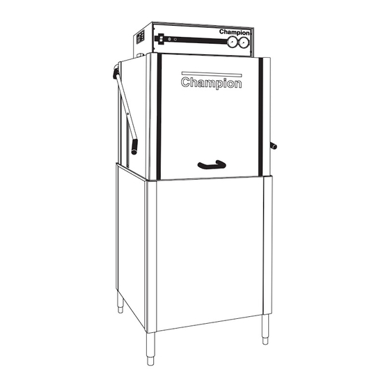
Door-type
Dishwasher
Models:
D-HBM5
High Temperature with
Built-in Booster Heater
D-H1M5
High Temperature
D-LFM5
Low Temperature
Manual P/N 113491 rev. J
2674 N. Service Road, Jordan Station
Ontario, Canada L0R 1S0
1-800 263-5798 Fax: 1-905 562-4618
Issued 5.26.10
Printed in U.S.A.
Parts
Advertisement
Chapters
Table of Contents

Related Manuals for Champion D-HBM5


Summary of Contents for Champion D-HBM5
- Page 1 Manual P/N 113491 rev. J www.championindustries.com Champion Industries, INC. 2674 N. Service Road, Jordan Station Printed in U.S.A. 3765 Champion Boulevard, Winston-Sale, NC 27105 Ontario, Canada L0R 1S0 P.O. Box 4149 Winston-Salem, NC 27115-4149 1-800 263-5798 Fax: 1-905 562-4618 1-800 232-8591 Fax: 1-800-661-1556...
- Page 2 The USGBC and the CaGBC Member Logos are trademarks owned by the U.S. Green Building Council and The Canadian Green Building Council, respectively, and are used by permission. The logos signify only that Champion Industries and Moyer Diebel are a USGBC member and a CaGBC member respectively. USGBC and CaGBC do not review, certify nor endorse the products or services offered by its members.
- Page 3 USE CANADIAN WARRANTY CARD IN CANADA AND USA WARRANTY CARD IN THE UNITED STATES. NO POSTAGE NECESSARY IF MAILED IN THE UNITED STATES BUSINESS REPLY MAIL FIRST-CLASS MAIL PERMIT NO. 2101 WINSTON-SALEM, NC POSTAGE WILL BE PAID BY ADDRESSEE CHAMPION INDUSTRIES INC PO BOX 4149 WINSTON-SALEM, NC 27119-0981...
- Page 4 WARRANTY REGISTRATION CARD Model Serial # Date of Installation: Company Name: Address: (Street) State or Province Zip Code Telephone #: ( Contact: Installation Company: Address: Telephone #: Contact: This Card Must Be Returned to Validate Machine Warranty: IMPORTANT IMPORTANT WARRANTY REGISTRATION CARD Model Serial # Date of Installation:...
-
Page 5: Revision History
Revision History Revision History A revision might be a part number change, new instructions, or information that was not available at the time of printing. We reserve the right to make changes to this manual without notice and without incurring any liability by making changes. Dishwasher owners may request a revised manual at no charge by calling (800) 858-4477 in the USA or (800) 263-5798 in Canada. Revision Date Pages Serial No. Effectivity Description 6.1.02 All D3694 Release of First Edition 10.18.02 11 D3858 Revised cycle times 10.18.02 36,37 D3858 Revised rinse arm bearing P/N's Bearing 112164 replaced by 113514, 0707453 replaced by 414111. 10.18.02 37 D3858 Added new rinse arm P/N 414110 for DHB/DH1 and 414111 for DLF. 10.18.02 39 D3851 Added water deflector P/N 327283. 10.24.02 47 D3700 Added bushing P/N 100171. - Page 6 Revision History (continued) Revision History (continued) Revision Date Pages Serial No. Effectivity Description 2.2.10 All D09117934 Release of Second Edition 4.30.10 2-3 D09117934 Revised pallet instructions 4.30.10 D09117934 Revised vent fan signal instructions 5.26.10 D09117934 Changed Item 10, P/N 113315 to P/N 114471 5.26.10 42-43 D09117934 Revised illustration to show Item 20, P/N 110561...
-
Page 7: Model Descriptions
Model Descriptions Model Descriptions Model Numbers D-HB - High Temperature sanitizing with built-in booster D-H1 - High Temperature sanitizing without built-in booster D-LF - Low Temperature Chemical sanitizing for use with a sodium hypochlorite (Chlorine) based sanitizer at a minimum concentration of 50 ppm in the final rinse. Standard Equipment Automatic Tank Fill and start Built-in electric booster heater (DHB only) in 40˚F/22˚C rise for 140˚F/60˚C supply water Balanced door lift system Electric tank heat Low-water tank heat protection Door safety switch Automatic electric drain Common utility connection Chemical connection provisions Stainless steel front and side panels Mounted water pressure regulating valve (DHB only) Interchangeable upper and lower spray arms Stainless steel rinse arms Straight-through operation Two dish racks (1 peg, 1 flat-bottom) Options and Accessories Built-in electric booster heater (DHB only) in 70˚F/39˚C rise for 110˚F/43˚C supply water Externally mounted steam booster (steam booster 40˚F/22˚C - 70˚F/39˚C rise) Steam injector or steam coil tank heat (steam booster 40˚F/22˚C - 70˚F/39˚C rise) Single Source gas booster heater Corner operation Additional dish racks: Peg rack P/N 101285 Flat-bottom P/N 101273 Sheet Pan P/N 113281 3/4" NPT Pressure Regulating Valve (PRV) P/N 107550... -
Page 8: Limited Warranty
DISCLAIMER OF WARRANTIES AND LIMITATIONS OF LIABILITY. CHAMPION'S WARRANTY IS ONLY TO THE EX- TENT REFLECTED ABOVE. CHAMPION MAKES NO OTHER WARRANTIES, EXPRESS OR IMPLIED, INCLUDING, BUT NOT LIMITED, TO ANY WARRANTY OF MERCHANTABILITY, OR FITNESS OF PURPOSE. CHAMPION SHALL NOT BE LIABLE FOR INCIDENTAL OR CONSEQUENTIAL DAMAGES. -
Page 9: Table Of Contents
Table of Contents Table of Contents Model D-HB, D-H1, D-LF Door-type Dishwashers Revision History ........................Model Descriptions ......................Limited Warranty ......................... Installation ......................Operation ....................... Cleaning ......................... Maintenance ......................Troubleshooting ....................Service Replacement Parts .................. Electrical Schematics ................... - Page 10 Blank Page This Page Intentionally Left Blank...
-
Page 11: Installation
Installation Receiving !!ATTENTION!! Use caution when moving or lifting the dishwasher to prevent damaging the dishwasher or the installation site. Check doorway and passageway clearance before moving the dishwasher. Remove dishwasher front panel and check under the machine base for obstructions before moving. 1. - Page 12 Installation Removing the Dishwasher from its Shipping Pallet The dishwasher is bolted to the shipping pallet on two corners using 1/2-13 shipping bolts. These shipping bolts must be removed and discarded. The machine legs are stowed inside the machine for installation when the dishwasher is removed from the shipping pallet. Follow the instructions below to remove the dishwasher from its pallet.
- Page 13 Installation Removing the Dishwasher from its Shipping Pallet Carefully remove the dishwasher from the shipping pallet taking care to prevent damage to the lower panels. Tilt the machine forward and install the rear legs on the machine. Be sure to maintain support on the machine at all times.
- Page 14 Installation Door Conversion from Straight-through to Corner Configuration Dishwasher door configurations are determined at the time the machine is ordered; however, the doors can be changed in the field with the addition of a door conversion kit P/N 900839 for Straight-through to Corner or P/N 900865 for Corner to Straight-through.
- Page 15 Installation Replacing the tracks: Refer to Fig. 2 Remove the existing front track, save mounting hardware. Install Item 1, from kit using existing mounting hardware. Seal bolts with putty supplied in kit. Install items 2-6 from kit. Existing Existing track hardware (Remove and discard) Figure 2- Change the Tracks...
-
Page 16: Electrical Connections
Installation Electrical Connections WARNING: Electrocution or serious injury may result when working on an energized circuit. Disconnect power at the main breaker or service disconnect switch before working on the circuit. Lock-out and tag the breaker to indicate that work is being performed on the circuit. -
Page 17: Water Connections
Installation Water Connections NOTE: Plumbing connections must comply with local sanitary and plumbing codes. 1. Connect a 3/4" NPT hot water supply line to the dishwasher. The connection point is located behind the lower front panel of the machine. The line enters the machine from underneath the base. -
Page 18: Drain Connections
Installation Drain Connections 1. All models are GRAVITY DRAIN machines equipped with a 2" O.D. hose connection. 2. The maximum flow rate is 15 U.S. gpm/56.8 Lpm. 3. Drain height for all models must not exceed 8-7/8" [225mm] above the finished floor. 4. - Page 19 Blank Page This Page Intentionally Left Blank...
- Page 20 Installation Steam Coil Tank Heat and Steam Booster Heater The illustration below details a steam heated machine consisting of a tank heat steam coil and a mounted steam booster for the final rinse. Contact the factory for steam injector tank heat details. NOTE: Only qualified personnel should make dishwasher steam connections.
- Page 21 Installation Single Source Gas Booster Heater The illustration below details a single source gas heated machine consisting of a tank heat hot water coil and a gas-powered booster heater for the final rinse. The gas-powered booster provides hot water for the hot water coil and the final rinse. The booster will run on natural gas or propane which is specified at the time of order.
- Page 22 Installation Purging Air from the Dishwasher/Booster Heater System CAUTION: PERMANENT DAMAGE to the hot water recirculating pump can occur if the air is not purged from the dishwasher/booster heater system prior to placing the dishwasher into service. Follow the instructions carefully to prevent damage to the dishwasher hot water recirculating pump.
-
Page 23: Chemical Connections
Installation Chemical Connections 1. Use a qualified detergent/chemical supplier for detergent/chemical and dispensing equipment needs. 2. Labeled detergent control circuit connection terminals are provided in the control cabinet for detergent and rinse agent dispensing equipment (supplied by others). 3. The illustration below shows the terminal board for the machine. 4. - Page 24 Installation Door Safety Switch Dishwasher access doors are equipped with a door safety switch that automatically stops the dishwasher pump if a door is raised while the dishwasher is running. In addition, the dishwasher will not start if a door is left open. If the dishwasher is running and a door is raised, then lighted in-cycle light goes out and the pump stops.
- Page 25 Installation Scrap Screens and Screen Support 4. Make sure the scrap screen support is positioned across the wash tank and installed in the brackets at the front and rear of the tank. 5. Install the scrap screens.
-
Page 26: Check List
14. Push the Power Switch OFF. The dishwasher should drain for 10 minutes. 15. Check that floor drain handles the water volume leaving the dishwasher. 150°F/66°C 180-195°F 20-22 PSI 82-91°C CHAMPION INDUSTRIES, INC. WINSTON-SALEM,NC Wash Final Rinse Final Rinse Temperature... -
Page 27: Control Panel
A: ON/OFF power switch B: Start Push button C: In-cycle Light D: Wash Water Temperature Gauge E: Final Rinse Water Temperature Gauge F: Final rinse Water Pressure Gauge Champion POWER WASH RINSE START CYCLE W A R N I N G ! -
Page 28: Operation
1. Make sure the main power and water supplies are turned on and the dishwasher doors are closed. 2. Push the power switch to the ON position. The power switch will illuminate and the machine will fill with water. Champion POWER WASH RINSE... - Page 29 6. Open the dishwasher doors and insert a rack of soiled wares into the machine. Close the doors and press the Green Start push button. 7. The in-cycle light will illuminate and the cycle will begin. Champion POWER WASH RINSE...
-
Page 30: Operation Summary
Operation Operation Summary ACTION RESULT Push ON/OFF switch UP to the ON position. The power switch illuminates, machine fills automatically and wash water begins to heat. DHB booster begins to heat. Wait 10 minutes for water to reach proper temperature. Wash water temperature gauge should indicate minimum of 150˚F/60˚C. -
Page 31: Cleaning
Cleaning Cleaning Cleaning your dishwasher is the best maintenance you can perform. The cleaning intervals below are the minimum requirements for most dishwashers. You may need to clean your dishwasher more often when washing heavily soiled wares or during long hours of continuous operation. POWER To Drain The automatic drain valve will open for 10 minutes... - Page 32 Cleaning De-liming Lime (scale) deposits are the result of minerals contained in the water feeding the dishwasher and appear as a white haze on the surface of the dishwasher. Severe scaling can appear as a granular deposit. These deposits are a result of the mineral content in the geographic area of the machine's location.
-
Page 33: Maintenance
Maintenance Maintenance Weekly 1. Inspect all water lines for leaks and tighten at joints if required. 2. Clean any detergent residue from the exterior of the machine. 3. Check that the drain/overflow pipes seat tightly in their drains. 4. Clean any accumulated scale from the heating element. 5. -
Page 34: Troubleshooting
Troubleshooting Troubleshooting Before calling for service check the following conditions. 1. Dishwasher main power and water supply is on. 2. Machine has been assembled correctly. 3. Drain is closed. 4. Screens and pump intake screen are clear. 5. Doors are closed and secure. Condition Cause Solution... - Page 35 Troubleshooting Troubleshooting (continued) Condition Cause Solution Insufficient pumped Clogged pump intake Clean. spray pressure screen. Clogged spray arm. Clean. Scrap screen full. Clean. Pump motor rotation wrong Reverse L1 and L2. Defective pump seal. Replace pump seal. Insufficient or no final Main water supply off.
- Page 36 Blank Page This Page Intentionally Left Blank...
-
Page 37: Service Replacement Parts
Service Replacement Parts Service Replacement Parts Illustration Page Panels, Doors and Gauges ........................28 Doors, Guides, Stops and Lift Bracket .......................30 Door Handle and Spring Assembly......................32 Track Assembly ............................34 Wash/Rinse Spray Piping ...........................36 Wash and Rinse Spray Arms ........................38 Drain Assembly and Scrap Screens ......................40 Wash Tank Heat, Thermostats and Float Switch ..................42 Electric Booster Assembly ..........................44 K2 Steam Booster Assembly ........................46... -
Page 38: Panels, Doors And Gauges
Panels, Doors and Gauges... - Page 39 Panels, Doors and Gauges Item Part Description 325405 SIDE DOOR, RIGHT 325407 SIDE DOOR, RIGHT (CORNER MACHINE) 327127 DOOR, FRONT 100779 SCREW, 1/4-20 X 5/8" TRUSS HD., SST 321932 PANEL, FRONT 321941 PANEL, LH WITH CUT-OUT 108418 PLUG, PLASTIC 109034 WASHER, 3/16"...
-
Page 40: Doors, Guides, Stops And Lift Bracket
Door Guides, Stops and Lift Bracket... - Page 41 Door Guides, Stops and Lift Bracket Item Part Description 108053 PLUG, CORNERPOST 107966 GRIP NUT, 10-32 W/NYLON INSERT 327104 BRACKET, DOOR LIFT 100007 SCREW, 10-32 X 3/8" TRUSS HD., SST 327103 BRACKET, LIFT DOOR 100097 SCREW, 10-32 X 1/2" TRUSS HD., SST 108347 GUIDE, DOOR 108410...
-
Page 42: Door Handle And Spring Assembly
Door Handle and Spring Assembly... - Page 43 Door Handle and Spring Assembly Item Part Description 112723 BOLT, 5/16-18 X 13" HEX HD., SST 108066 SPRING, EXTENSION 107397 BLOCK, SPRING HOOK 0509166 HANDLE, DOOR (STRAIGHT-THROUGH) 112859 HANDLE, DOOR (CORNER MACHINE) 107437 BOLT, M6 X 45 MM HEX HD., SST 107396 BLOCK, UPPER PIVOT 107393...
-
Page 44: Track Assembly
Track Assembly... - Page 45 Track Assembly STRAIGHT-THROUGH TRACK CONFIGURATION Item Part Description 0309472 TRACK, REAR 100073 BOLT, 1/4-20 X 1/2" TRUSS HD., SST 106482 WASHER, LOCK 1/4" SPLIT SST 100003 NUT, PLAIN 1/4" HEX HD., SST CORNER TRACK CONFIGURATION Item Part Description 0309469 GUIDE, RIGHT HAND 0309472 TRACK, REAR 0309468...
-
Page 46: Wash/Rinse Spray Piping
Wash/Rinse Spray Piping... - Page 47 Wash/Rinse Spray Piping Item Part Description 324526 MANIFOLD, RINSE WELDMENT 113027 CONNECTOR, RINSE ARM 113028 CONNECTOR, TOP RINSE 0507445 SPINDLE, WASH ARM 109864 SUPPORT, WASH ARM 109781 STANDPIPE, WASH 100736 BOLT, 1/4-20 X 3/4" HES HD., SST 107967 GRIP NUT, 1/4-20 109854 GASKET, WASH STANDPIPE 100740...
-
Page 48: Wash And Rinse Spray Arms
Wash and Rinse Spray Arms After S/N D3858 Prior to S/N D3858... - Page 49 Wash and Rinse Spray Arms Item Part Description 0507443 SPINDLE, RINSE ARM 0508376 NOZZLE, RINSE ARM (DHB, DH1 Only) Prior to D3858 113514 BEARING, RINSE ARM 414111 RINSE ARM ASSY COMPLETE (DHB, DH1 Only) (Prior to D3858) RINSE ARM ASSY COMPLETE 414110 (DHB, DH1 Only) (Beginning with D3858) 0507444...
-
Page 50: Drain Assembly And Scrap Screens
Drain Assembly and Scrap Screens... - Page 51 Drain Assembly and Scrap Screens Item Part Description 305164 SCREEN 10" 324582 PLATE, FILLER 100736 BOLT, 1/4-20 X 3/4" HEX HD., SST 106026 WASHER, FLAT 1/4" SST 107967 GRIP NUT, 1/4-20 HEX HD., SST 304816 STRAINER 205988 CONNECTOR, ELECTRIC DRAIN VALVE 104165 CLAMP, HOSE 205990...
-
Page 52: Wash Tank Heat,Thermostats And Float Switch
Wash Tank Heat,Thermostats and Float Switch... - Page 53 Wash Tank Heat, Thermostats and Float Switch Item Part Description 113622 THERMOMETER, 4FT. CAPILLARY 109069 THERMOSTAT W/CAPILLARY 201041 WASHER 201029 NUT, LOCK 1/2" 322076 BRACKET, DUAL THERMOSTAT 107089 NUT, JAM 1/2-13 104882 WASHER 111092 SWITCH, FLOAT 111151 C-CLIP, FLOAT SWITCH 100740 BOLT, 5/16-18 X 1"...
-
Page 54: Electric Booster Assembly
Electric Booster Assembly... - Page 55 Electric Booster Assembly Item Part Description 100740 BOLT, 5/16-18 X 1" HEX HD., SST 102376 WASHER, FLAT 5/16" SST 108954 GRIP NUT, 6-32 W/NYLON INSERT, SST 110562 THERMOSTAT, HIGH LIMIT SNAP 110563 COMPOUND, HEAT SINK 109069 THERMOSTAT, CONTROL W/CAPILLARY 100003 NUT, PLAIN 1/4-20 SST 106482 WASHER, LOCK 1/4"...
-
Page 56: K2 Steam Booster Assembly
k2 Steam Booster Assembly 5 10... - Page 57 K2 Steam Booster Assembly Item Part Description 110189 BOOSTER, K2 SPIREX 315596 BRACKET, BOOSTER SUPPORT 105725 COUPLING REDUCING, 1" X 3/4" NPT BI 102442 ELBOW, 3/4" NPT X 90° BRASS 105803 NIPPLE, CLOSE 3/4" NPT BI 106485 UNION ELL, 3/4" NPT X 90° FEMALE BI 107502 UNION ELL, 3/4"...
-
Page 58: Hot Water Coil Tank Heat Assembly
Hot Water Coil Tank Heat Assembly NOT SHOWN 17 12 GRUNDFOS... - Page 59 Hot Water Coil Tank Heat Assembly Item Part Description 322280 COIL WELDMENT, STEAM/HOT WATER 100585 LOCKNUT, 1/" NPT BRASS 100184 NIPPLE, CLOSE 3/4" NPT BRASS 107418 TEE, 3/4" X 3/4" X 1/4" BRASS 102442 ELBOW, 3/4" NPT BRASS 100571 UNION, 3/4" NPT BRASS 112437 NEEDLE VALVE, 1/4"...
-
Page 60: Single Source Gas Booster Piping
Single Source Gas Booster Piping STANDARD REAR FLUE EXHAUST OPT. RIGHT HAND END FLUE EXHAUST APOLLO s"CLOSE s"CLOSE 110° HOT WATER IN TO BOOSTER WATER RETURN FROM COIL AND RETURN FROM TANK HEAT COIL HOT WATER RETURN FROM COIL TO BOOSTER s"CLOSE HOT WATER IN FROM BOOSTER TO COIL... - Page 61 Single Source Gas Booster Piping Item Part Description 102521 TEE, 3/4" NPT BRASS 100184 NIPPLE, CLOSE 3/4" NPT BRASS 107550 PRESSURE REGULATING VALVE 3/4" NPT BRONZE 102651 NIPPLE, 3/4" NPT X 2" LG. BRASS 102669 NIPPLE, 3/4" NPT X 8-1/2" LG. BRASS 102660 NIPPLE, 3/4"...
-
Page 62: Dhb Lower Fill Piping Assembly
DHB Lower Fill Piping Assembly TO UPPER PIPING CUSTOMER WATER INLET... - Page 63 DHB Lower Fill Piping Assembly Item Part Description 107550 VALVE, PRESSURE REGULATING 3/4" 102444 STREET ELL, 3/4" X NPT BRASS 102651 NIPPLE, 3/4" X 2" BRASS 111437 VALVE, 3/4" NPT HOT WATER 120VAC 100184 NIPPLE, CLOSE 3/4" NPT BRASS 102442 ELBOW, 3/4"...
-
Page 64: Dhb, Dh1 Upper Fill Piping Assembly
DHB, DH1 Upper Fill Piping Assembly WATER IN FROM LOWER PIPING FINAL RINSE THERMOMETER BULB... - Page 65 DHB, DH1 Upper Fill Piping Assembly Item Part Description 100156 LOCKNUT, 3/4" NPT BRASS 100571 UNION 3/4" NPT BRASS 100184 NIPPLE, CLOSE 3/4" NPT BRASS 107463 PLUG, 1/4" NPT PLASTIC 108181 BUSHING, RED. 3/4" X 1/4" NPT PLASTIC 100599 CROSS, 3/4" NPT BRASS 102444 ELBOW, STREET 3/4"...
-
Page 66: Dlf Upper Fill Piping Assembly
DLF Upper Fill Piping Assembly WATER IN FROM LOWER PIPING FINAL RINSE THERMOMETER BULB... - Page 67 DLF Upper Fill Piping Assembly Item Part Description 100548 LOCKNUT, 3/4" NPT SST 102554 UNION, 3/4" NPT SST 100051 NIPPLE, CLOSE 3/4" NPT SST 107463 PLUG, PLASTIC 1/4" 108181 BUSHING RED. 3/4" X 1/2" NPT PLASTIC 205993 CROSS, 3/4" NPT SST 100184 NIPPLE, CLOSE 3/4"...
-
Page 68: Dh1, Dlf Lower Fill Piping Assembly
DH1, DLF Lower Fill Piping Assembly TO UPPER PIPING CUSTOMER WATER IN... - Page 69 DH1, DLF Lower Fill Piping Assembly Item Part Description 102444 STREET ELL, 3/4" NPT BRASS 0309340 BRACKET, PLUMBING SUPPORT 110768 STRAINER, LINE 3/4" BRASS 111437 VALVE, 3/4" NPT HOT WATER, 12OVAC 100184 NIPPLE, CLOSE 3/4"NPT BRASS 109879 COMPRESSION FITTING, 3/4" NPT X 7/8" OD BRASS 102442 ELBOW, 3/4"...
-
Page 70: Pump Assembly
Pump Assembly... - Page 71 Pump Assembly Item Part Description 324580 STRAINER 107966 GRIP NUT, 10-32 W/NYLON INSERT 104203 CLAMP, HOSE 104165 CLAMP, HOSE 107340 CLAMP, HOSE 112383 HOSE, PUMP DISCHARGE 0508515 HOSE, SUCTION 100734 BOLT, 1/4-20 X 1/2" HEX HD., SST 106482 WASHER, LOCK 1/4" SPLIT SST 110247 NUT, HEX JAM 7/16-20 110248...
-
Page 72: Control Cabinet Assembly
FLOAT SW. LAMP OUTPUT EXT. WASH FILL RINSE WASH Champion POWER WASH RINSE START CYCLE W A R N I N G ! T U R N O F F P O W E R B E F O R E... - Page 73 Control Cabinet Assembly Item Part Description 111833 TERMINAL BLOCK, 1 &3 PH 103310 WIRE LUG, GROUND 111702 CONTACTOR, BOOSTER (MV 3PH) 40/70°F RISE 111702 CONTACTOR, TANK HEAT (MV 1 & 3 PH) 109582 CONTACTOR, WASH MOTOR 1PH 108122 CONTACTOR, WASH MOTOR 3 PH 111632 STARTER, MOTOR WASH 115V/1PH 111630...
-
Page 74: Dish Racks, Prv
Dish racks, PRV... - Page 75 Dish racks, PRV Item Part Description 101273 RACK FLAT BOTTOM 101285 RACK, PEG 107550 VALVE, PRESSURE REGULATING (PRV)
- Page 76 Blank Page This Page Intentionally Left Blank...
Need help?
Do you have a question about the D-HBM5 and is the answer not in the manual?
Questions and answers