
Related Manuals for Mircom TX3 Series


Summary of Contents for Mircom TX3 Series
- Page 1 TX3 Series TX3 EMERGENCY PHONE Installation and Operation Manual Version 2 Mircom LT-6113 Copyright June 2017...
- Page 2 The content of this manual is furnished for informational use only. It is subject to change without notice, and should not be construed as a commitment by Mircom. Mircom assumes no responsibility or liability for any errors or inaccuracies that appear in this book.
-
Page 3: Table Of Contents
Contents Introduction TX3 Emergency Phone Features Accessories Warranty and Special Notices About This Manual 1.5.1 Version Control 1.5.2 Additional Documentation Contact Us 1.6.1 General Inquiries 1.6.2 Customer Service 1.6.3 Website 1.6.4 Email 1.6.5 Technical Support Installation Dimensions Mounting Mounting the Emergency Phone with the optional trim ring Wiring the Controller Board 2.4.1 Connectors... - Page 4 Contents Install the Configurator Connect to the Emergency Phone 3.3.1 Connect to an existing TX3 network 3.3.2 Connect to one or more Emergency Phones Programming Inputs and Outputs Correlations Program the Buttons Program the Emergency Phone from the Keypad Dial from the Keypad TX3 System TX3 System Single Emergency Phone...
- Page 5 List of Figures Figure 1 Front of the Emergency Phone Figure 2 Dimensions of the Emergency Phone Figure 3 Mounting the Emergency Phone with the trim ring Figure 4 Emergency Phone Main Controller Board Figure 5 Microphones and JW11 Figure 6 Controller Board Connectors for -C Models - Bottom Figure 7 3 Terminal Controller Board Connectors - Bottom...
-
Page 6: Introduction
Installation must be performed by a qualified technician and must adhere to the standards and special notices set by the local regulatory bodies. Note: Mircom periodically updates panel firmware and Configurator Software to add features and correct any minor inconsistencies. For information about the latest firmware or software visit the Mircom website at www.mircom.com. -
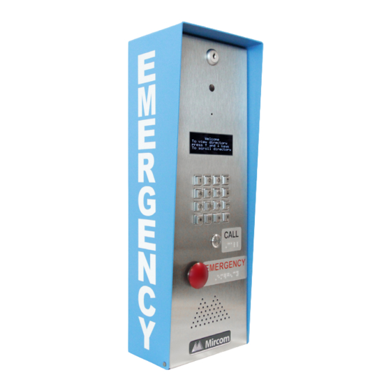
Page 7: Tx3 Emergency Phone
Introduction TX3 Emergency Phone Mircom’s TX3 Emergency Phone provides high quality two-way communication between residents or visitors and the concierge or guard in a multi-unit dwelling establishment. The are two configurable buttons on the front of the Emergency Phone. The Emergency Call Button can be programmed to call an emergency hotline. -
Page 8: Features
Introduction Features Features of the Emergency Phone include: • Vandal-resistant, high quality intercom and paging device • Stainless steel front panel with vandal-resistant microphone and speaker openings • 4 line OLED display • Provision for a camera • Storage of up to 200 names (TX3-EMER-200KS version only) •... -
Page 9: Warranty And Special Notices
Introduction Warranty and Special Notices Mircom values your business and always attempts to provide you with the very best service. Please see the Warranty and Special Notices chapter on page 56 for information about the warranty and special notices about equipment use. -
Page 10: Contact Us
Toll-Free Fax: 1-888-660-4113 1.6.3 Website Visit the Mircom website, at www.mircom.com, to find the product information you are looking for and to learn about troubleshooting, training and technical support options. The website provides avenues for customers to ask questions about new and existing technologies, and receive expert technical support about software and products. -
Page 11: Email
As a customer you quickly become informed on how we can help with new products and technologies. Contact Mircom at mail@mircom.com. 1.6.5 Technical Support For technical support contact Mircom’s Technical Support Department between 8 A.M. and 5 P.M. (EST) Monday through Friday, excluding holidays. Toll Free: 1-888-MIRCOM5 Local: 905-695-3535... -
Page 12: Installation
Installation This chapter provides information on how to install and wire the Emergency Phone. This chapter explains • Dimensions • Mounting • Mounting the Emergency Phone with the optional trim ring • Wiring the Controller Board • Controller Board Connectors - Bottom •... -
Page 13: Dimensions
Installation Dimensions 5 27/32” 4 1/2” (114 mm) (149 mm) 3 13/32” (86 mm) 15 13/64” 16 5/8” 5 17/32” (386 mm) 394 mm) (422 mm) 3 3/8” 1 27/64” (86 mm) (36 mm) Figure 2. Dimensions of the Emergency Phone TX3 Emergency Phone Installation and Operation Manual Version 2 LT-6113... -
Page 14: Mounting
• Knockout diameter: 7/8” (22 mm) and 1 1/8” (29 mm) The emergency phone mounts on the wall. Mount the enclosure right-side up (the Mircom logo on the door is on the bottom). You need: • 4 fasteners appropriate for the wall that you are mounting the enclosure on. -
Page 15: Mounting The Emergency Phone With The Optional Trim Ring
Installation Mounting the Emergency Phone with the optional trim ring Mount the semi-flush trim into the wall cut out, attach to the wall stud, left or right using the two slot holes on the side of the semi-flush trim ring. Place the Emergency Phone inside the trim ring. -
Page 16: Wiring The Controller Board
Installation Wiring the Controller Board All wiring is a maximum length of 1000 ft (304.8 m). The RS-485 wiring maximum length is 4000 ft (1219.2 m). Figure 4 shows the general layout of the Emergency Phone main controller board. Door Supply, Door Telephone Relay, and 2 General lines 1 to 5... -
Page 17: Connectors
Installation Figure 4. Emergency Phone Main Controller Board 2.4.1 Connectors USB. Computer connection for firmware download and configuration. P4. TX3-MDM Modem Board connector. P5. MD-921 IP Module Board connector. P6. Key pad and front door LCD display. P7. Guard Phone Board connector. 2.4.2 Potentiometer PT1 (if present). -
Page 18: Controller Board Connectors - Bottom
Installation JW11: • If the panel has the MC-001 microphone, close JW11. • If the panel has the MC-012 or MD-1243 microphone, open JW11. MD-1243 microphone MC-012 microphone MC-001 microphone JW11 off or open JW11 off or open JW11 on or closed Figure 5 Microphones and JW11 Controller Board Connectors - Bottom... -
Page 19: Figure 7 3 Terminal Controller Board Connectors - Bottom
Installation Figure 7 shows the connectors for older models. Note: Both models of microphone are shown in Figure 7. Connect only one microphone at a time, and set JW11 correctly depending on the microphone. See section 2.4.4 on page 17. - s + LED/LAMP Supply... -
Page 20: Controller Board Connectors - Top
Installation Controller Board Connectors - Top Figure 8 shows the connectors at the top of the controller board. Line 1 Line 5 General Relay Door Strike Output 4 DC Output 1 Door Strike AC or DC Input Door Line 2 Line 3 Line 4 Strike Supply... -
Page 21: Telephone Lines 1 To
General Relay Outputs 3 and 4 Outputs 3 and 4 are relay contact programmable outputs. See LT-995 on the USB disk or Mircom website for details on programming these relays. Output 4 controls the optional strobe. See section 2.9 on page 26. -
Page 22: Camera Supply
Installation 2.6.6 Camera Supply The camera supply connection provides + 12 VDC, 600 mA. The camera is controlled by one of the general outputs. The camera’s positive terminal connects to the normally open (NO) general output relay contact. The common (C) contact of the general output relay connects to the + 12 VDC supply terminal. -
Page 23: Setting The Rs-485 Address
Installation Setting the RS-485 Address Use DIP switches 1-6 to set the RS-485 network address. The individual switches are numbered 1 to 8 from left to right, and are marked as either ON or OFF. The first six switches (1, 2, 3, 4, 5 and 6) set the address. Every TX3 Emergency Phone requires a unique address. - Page 24 Installation Table 1: Emergency Phone SW1 DIP Switch Settings Emergency Phone Unit Switch 1 Switch 2 Switch 3 Switch 4 Switch 5 Switch 6 ID # TX3 Emergency Phone Installation and Operation Manual Version 2 LT-6113 Copyright 2017...
- Page 25 Installation Table 1: Emergency Phone SW1 DIP Switch Settings Emergency Phone Unit Switch 1 Switch 2 Switch 3 Switch 4 Switch 5 Switch 6 ID # TX3 Emergency Phone Installation and Operation Manual Version 2 LT-6113 Copyright 2017...
-
Page 26: Connect The Optional Strobe
Installation Connect the Optional Strobe See Chapter 4 on page 40 for information on how the strobe is programmed. Connect the strobe’s + wire to the + terminal of the Camera Supply. Connect the strobe’s - wire to the NO terminal of Output 4 at the top of the board. -
Page 27: Grounding
Installation 2.10 Grounding Grounding reduces the risk of electrical shock by providing an alternate escape route for the electrical current. A missing ground can also affect audio quality. The Emergency Phone is equipped with a 16 gauge electrical wire attached to the panel chassis ground post as shown in Figure 12. -
Page 28: Connect The Power
Installation 2.11 Connect the Power Note: Install all transformers outside the Emergency Phone enclosure. The power supply connection is situated at the bottom right of the main controller board and receives 16 VAC, 40 VA. An external PS-4 or PS-4P plug-in transformer connects to the power terminals. -
Page 29: Installing The Heater
Installation 2.12 Installing the Heater For temperatures where the Emergency Phone operates below 0°C (32°F) at any time, a heater must be installed inside the enclosure as shown in Figure 14. For additional information refer to LT-653 TH-102 Heater Installation Instructions. -
Page 30: Installing The Optional Md-921 Ip Module
Installation 2.13 Installing the Optional MD-921 IP Module The MD-921 IP Module connects the Emergency Phone to an Ethernet TCP/IP network. The MD-921 IP Module ribbon cable connects to the P5 connector on the controller board (see Figure 4 on page 17). This allows you to configure and monitor the TX3 devices on your system using a computer and an Ethernet connection. -
Page 31: Installing The Optional Guard Phone Module
Installation 2.14 Installing the Optional Guard Phone Module The TX3-GPM Guard Phone Module mounts above the Emergency Phone main board on the top left hand side. See Figure 4 on page 17. The module has two connectors, an RJ-11 connector and a ribbon cable as shown in Figure 16. -
Page 32: Updating Firmware
Refer to LT-995, TX3 Configuration and Administrator Manual, for instructions on how to perform both of these firmware upgrade methods. LT-995 can be found on the TX3 Configurator Software installation CD, USB flash drive, or on the Mircom website. TX3 Emergency Phone Installation and Operation Manual Version 2... -
Page 33: Connecting
Connecting This chapter provides instructions on connecting a computer to the Emergency Phone in order to program it. For detailed instructions on using the Configurator, see LT-995. This chapter explains • PC System Requirements • Install the Configurator • Connect to the Emergency Phone TX3 Emergency Phone Installation and Operation Manual Version 2 LT-6113... -
Page 34: Pc System Requirements
Connecting PC System Requirements For the PC based Configurator the minimum system requirements are: • Windows 8 • Windows 7 (32 bit) • Windows XP SP2 • 512 MB RAM • 1 GHZ CPU • 600M disk space • 1 USB port Note: Firmware upgrade is not supported on 64-bit systems. -
Page 35: Connect To An Existing Tx3 Network
Connecting 3.3.1 Connect to an existing TX3 network Open the TX3 Configurator. Open the job for your network. Click Edit > Add Panel. The Add Panel window appears. Figure 17. Add Panel In the Label field, type a name for the Emergency Phone. In the Address menu, select the RS-485 address of the Emergency Phone. -
Page 36: Connect To One Or More Emergency Phones
Connecting 3.3.2 Connect to one or more Emergency Phones If you do not have an existing TX3 network and you are connecting to one or more networked Emergency Phone, follow these instructions. You must: Create a new job Delete the panel Add the Emergency Phone Connect to the Emergency Phone Follow the instructions below to complete these steps. -
Page 37: Figure 19 New Job
Connecting Click OK. The Job tree on the left shows the job that you just created. Figure 19. New Job Delete the panel Right-click the panel in the Job tree, and then click Delete. Click Yes to confirm. Note: When you create a job, a panel is automatically added. The panels in your job must match the panels that you are connecting to. -
Page 38: Figure 20 Add Panel
Connecting Add the Emergency Phone Click Edit, and then click Add Panel. The Add Panel window appears. Figure 20. Add Panel In the Label field, type the name of the panel, for instance Emergency Phone 1. In the Address menu, select the RS-485 address of the Emergency Phone that you are connecting to. -
Page 39: Figure 21 New Job With Emergency Phone
Connecting The Job tree on the left shows the Emergency Phone that you just added. Figure 21. New Job with Emergency Phone Repeat steps 1-5 for each Emergency Phone on the network. Connect to the Emergency Phone Select Network in the job tree. In the Network Configuration window, select the method that you are using to connect the computer to the Emergency Phone. -
Page 40: Programming
Programming The Emergency Phone functions like a lobby control unit in the Configurator. See LT-995 on the USB disk or Mircom website for instructions on configuring a lobby control unit. This chapter discusses the inputs, outputs, and correlations that are specific to the Emergency Phone. -
Page 41: Inputs And Outputs
Programming Inputs and Outputs The Emergency Phone has 5 inputs and 4 outputs. Inputs 4 and 5, and Output 1, are wired to the following components: • Input 4: Emergency Call Button • Input 5: Operator Call Button • Output 4: Strobe (optional) Correlations The Configurator has four default correlations. -
Page 42: Figure 23 Emergency Call Button
Programming The details for the Emergency Call Button appear. Figure 23. Emergency Call Button In the Phone number field, type the phone number that the Emergency Call Button should dial (or SIP ID if you are using a VoIP modem). Click OK. -
Page 43: Program The Emergency Phone From The Keypad
Program the Emergency Phone from the Keypad You can program the Emergency Phone model TX3-EMER-200KS from the keypad. See LT-979 on the USB disk or Mircom website for details. Dial from the Keypad You can dial the numbers from the keypad instead of pressing the Emergency Call Button or the Operator Call Button. - Page 44 Programming To dial the Operator Call Button from the keypad Dial 9 9 9 2 on the keypad, and then press the telephone key. Press the star key to hang up. TX3 Emergency Phone Installation and Operation Manual Version 2 LT-6113 Copyright 2017...
-
Page 45: Tx3 System
TX3 System This chapter provides information about the TX3 System and its use. This chapter explains • TX3 System • Single Emergency Phone • Dual Emergency Phones • Multiple Emergency Phones • Networking TX3 Panels TX3 Emergency Phone Installation and Operation Manual Version 2 LT-6113 Copyright 2017... -
Page 46: Tx3 System
TX3 System TX3 System The TX3 Emergency Phone can be networked with a combination of card access units and lobby control units through a peer-to-peer RS-485 connection. The TX3 system is capable of providing ADC telephone access from a single panel or from a networked system. -
Page 47: Single Emergency Phone
TX3 System Single Emergency Phone Figure 25 shows the simplest configuration. Telephone outlet Central office line Line1 Figure 25. Single Emergency Phone TX3 Emergency Phone Installation and Operation Manual Version 2 LT-6113 Copyright 2017... -
Page 48: Figure 26 Single Entrance System Wiring
TX3 System Figure 26 shows the various inputs to and outputs from the panel. Telephone outlet Central office line Electrical room INPUTS OUTPUTS Line1 General 1 pair purpose output Aux Door Telephone form C relay Fire panel Main Door Form C relay AC or DC wire contacts 1... -
Page 49: Dual Emergency Phones
TX3 System Dual Emergency Phones Figure 27 shows a dual entry application. The phone line is shared by both Emergency Phones. The Emergency Phone senses whether the line in use. If one of the Emergency Phones is in use and the user tries to make a call, the other Emergency Phone indicates that the line is in use. -
Page 50: Multiple Emergency Phones
TX3 System Multiple Emergency Phones Figure 28 shows a configuration of many Emergency Phones to one phone line. Telephone outlet Central office line Line Line Line Line Line Emergency Emergency Emergency Emergency Emergency Phone Phone Phone Phone Phone unit 3 unit 5 unit 2 unit 4... -
Page 51: Networking Tx3 Panels
TX3 System Networking TX3 Panels Mircom devices such as the Emergency Phone, lobby control unit, the card access unit, and the Touch Screen can be networked with the TX3 system through a peer-to-peer RS-485 network, an Ethernet TCP/IP network, or a combination of Ethernet and RS-485 networks. -
Page 52: Figure 30 Tx3 Devices On An Ethernet Tcp/Ip Network
TX3 System the Ethernet TCP/IP network. If you connect directly to one of the Master Nodes using USB, a modem, or a COM port, you will be able to configure that device but not any other device. Lobby Control Unit Lobby Control Unit Card Access Controller (Master Node) -
Page 53: Figure 31 Lobby Control Units Using Both Ethernet And Rs-485
TX3 System Figure 31 shows a configuration with TX3 devices connected on both an Ethernet TCP/IP network and on RS-485 subnetworks. Devices connected to a Master Node’s RS-485 subnetwork are Slave Nodes to the Master Node. Each RS-485 subnetwork can have up to 63 devices connected to it; you can still have more than 63 Master Nodes connected to the Ethernet network. -
Page 54: Specifications
AC Power Supply 105 VAC to 128 VAC. Power Transformer Mircom Model PS-4. 16 VAC/ 40 VA, CSA approved Class 2 Power Transformer. Mircom Model PS-4P. 16 VAC/ 40 VA, CSA approved Class 2 Power Transformer, plug-in. Door Strikes Select the appropriate door strike as required by your system applications. -
Page 55: Outputs
Specifications The maximum supply for the AC or DC Input Door Strike must not exceed: • 28 VAC / 1 A max • 30 VDC / 1 A max Outputs 2-4 Form C relays with these contact ratings: • 125 VAC / 2 A •... -
Page 56: Warranty & Warning Information
During the warranty period, Mircom shall, at its option, repair or replace any defective product upon return of the product to its factory, at no charge for labour and materials. - Page 57 Mircom neither assumes nor authorizes any other person purporting to act on its behalf to modify or to change this warranty, nor to assume for it any other warranty or liability concerning this product.
- Page 58 Products which Mircom determines to be repairable will be repaired and returned. A set fee which Mircom has predetermined and which may be revised from time to time, will be charged for each unit repaired. Products which Mircom determines not to be repairable will be replaced by the nearest equivalent product available at that time.
-
Page 59: Special Notices
Special Notices Product Model Number: TX3 AC REN (U.S.): 0.0B AC REN (CANADA): 0.0 Complies With Federal Communications Commission (FCC): • TIA-968-A Technical requirement for connection of equipment tot he telephone network. • CFR 47, Part 15, Subpart B, Class B •... - Page 60 Repairs to certified equipment should be made by an authorized Canadian maintenance facility designated by the supplier. Any repairs or alteration made by the user to this equipment, or equipment malfunctions, may give the telecommunications company cause to request the user to disconnect the equipment.
- Page 61 Contact your telephone company if you have any questions about your telephone line. In the event repairs are ever needed on the Communicator, they should be performed by Mircom or an authorized representative of Mircom. For information contact Mircom at the address and telephone numbers in paragraph 1.6.
- Page 62 Equipment Failure If trouble is experienced with the TX3 Telephone/Card Access System, for repair or warranty information, please contact Mircom using the numbers paragraph 1.6. If the equipment is causing harm to the telephone network, the telephone company may request that you disconnect the equipment until the problem is resolved.
Need help?
Do you have a question about the TX3 Series and is the answer not in the manual?
Questions and answers