
Related Manuals for Mircom TX3 Series


Summary of Contents for Mircom TX3 Series
- Page 1 TX3 Series TX3-CX-1 Installation Manual TX3-CX-1 Installation Manual Version 1.1 LT-6618 Copyright September 2019...
- Page 2 Copyright September 2019 Mircom Inc. All rights reserved. Mircom TX3-CX-1 Installation Manual v.1.1 Microsoft, MS-DOS, Windows, and Windows 2000/NT/XP/Vista/7/8/10 are either registered trademarks or trademarks of Microsoft Corporation in the United States and/or other countries. Mircom 25 Interchange Way Vaughan, Ontario L4K 5W3 905.660.4655...
-
Page 3: Table Of Contents
Contents Welcome The TX3-CX-1 Single Door Controller Features Configuration Card Formats Installer Responsibilities Typical Wiring Diagram About This Manual Additional Documentation Installation of TX3-CX-1 Dimensions and Parts Wiring DIP Switches RS-485 External Card Reader USB Port Inputs Outputs Power 2.10 Mounting and Unmounting 2.11 Status LEDs... - Page 4 List of Figures Figure 1 Typical wiring diagram for TX3-CX-1 Figure 2 Dimensions of TX3-CX-1 Figure 3 Parts of TX3-CX-1 Figure 4 Terminal connections on TX3-CX-1 Figure 5 Setting the RS-485 address Figure 6 RS-485 Wiring Figure 7 Card reader connections Figure 8 Input Terminal Sample Connections Figure 9...
-
Page 5: Welcome
Note: Mircom periodically updates panel firmware and Configurator Software to add features and correct any minor inconsistencies. For information about the latest firmware or software visit the Mircom website at www.mircom.com. This chapter explains • The TX3-CX-1 Single Door Controller •... -
Page 6: The Tx3-Cx-1 Single Door Controller
Welcome The TX3-CX-1 Single Door Controller The TX3-CX Card Access System is part of the Mircom suite of products that provide building ready monitoring, control and integrated security solutions for use in the high end multi-tenant residential market. The TX3-CX-1 Single Door Controller has all the features for an entry level access control application with the flexibility for scalability. -
Page 7: Card Formats
• 36-bit Keyscan C15001 • 37-bit Cansec • 37-bit HID 10304 • 37-bit Mircom • 39-bit Kantech XSF • 50-bit RBH Installer Responsibilities The installation and setup must be done by a qualified technician. The technician is responsible for installing all of the system components, connecting all of the... -
Page 8: About This Manual
Welcome Figure 1. Typical wiring diagram for TX3-CX-1 About This Manual This manual applies to the following models: • TX3-CX-1 Single Door Controller Additional Documentation • LT-980 TX3 Card Access System Installation and Operation Manual • LT-995 TX3 Configuration and Administration Manual •... -
Page 9: Installation Of Tx3
Installation of TX3-CX-1 This manual describes the installation of the Single Door Controller. This chapter explains • Dimensions and Parts • Wiring • DIP Switches • RS-485 • External Card Reader • USB Port • Inputs • Outputs • Power •... -
Page 10: Dimensions And Parts
Installation of TX3-CX-1 Dimensions and Parts 4 25/32” (122 mm) 3 3/32” (79 mm) 1 39/64” (41 mm) Figure 2. Dimensions of TX3-CX-1 TX3-CX-1 Installation Manual Version 1.1 LT-6618 Copyright 2019... -
Page 11: Figure 3 Parts Of Tx3
Installation of TX3-CX-1 Mounting Body plate #6-32 x 1screws #6-32 x .25 screw Figure 3. Parts of TX3-CX-1 TX3-CX-1 Installation Manual Version 1.1 LT-6618 Copyright 2019... -
Page 12: Wiring
Installation of TX3-CX-1 Wiring RJ45 connector for Internet communication. Power can be provided Set ON if unit is used as first or last controller on through Power over Ethernet if not RS-485 network. Otherwise set OFF. The default setting is OFF. provided by the DC power terminals. -
Page 13: Figure 5 Setting The Rs-485 Address
Installation of TX3-CX-1 See chapter 3 on page 28 for the list of RS-485 addresses. Note: You must set the RS-485 address even if you are not using RS-485. Figure 5. Setting the RS-485 address RS-485 Note: To comply with UL 294, do not connect devices to the RS-485 port. -
Page 14: External Card Reader
Installation of TX3-CX-1 First controller on network Turn switch labeled “120 Ω” ON Turn switch labeled “120 Ω” OFF Last controller on network Turn switch labeled “120 Ω” ON Figure 6. RS-485 Wiring External Card Reader DATA 0 DATA 1 BEEP LED (RED) LED (GREEN) - Page 15 Orange LED (G) Card readers supplied by Mircom require a foil shielded multiple conductor stranded cable, 22-16 AWG. For example, use Belden 9535 or a similar cable. For other brands of card readers, follow the instructions in the manual for the card reader.
-
Page 16: Usb Port
Installation of TX3-CX-1 USB Port The USB port provides a connection to a PC for configuring the Card Access System and upgrading the firmware. Inputs Inputs 1 to 4 are programmable inputs. In the TX3 Configurator software, the inputs are configured as follows by default: •... - Page 17 Installation of TX3-CX-1 2.7.3 General purpose input The general purpose input is mainly used for establishing a correlation with a specific output. When a general purpose input becomes active it is considered as an event that correlates to either turn on or off a general purpose output, or to turn on or off the high security mode.
-
Page 18: Figure 9 Input - Supervised For Open
Installation of TX3-CX-1 2.7.5.2 Supervised for open When configured as supervised for open, the active state is ‘closed’ (short). Open supervision uses a single 47K ohm resistor. Active when short 47 K ohms Figure 9. Input - Supervised for Open Note: The active state cannot be an open state. -
Page 19: Outputs
Installation of TX3-CX-1 Two 22K ohm resistors are required for supervision. Active when short 22 K ohms 22 K ohms Figure 11. Input - Supervised for Open and Short Note: The active state cannot be an open state. 2.7.6 Alarm Delay Alarm delay is a Configurator defined parameter that specifies the amount of time before an input raises an alarm condition. -
Page 20: Figure 12 Outputs 1 And 2: Sample Connections
Installation of TX3-CX-1 • Output 2: General purpose. Door Strike Maglock External power supply External power supply Normally Closed Common Common Normally Open Figure 12. Outputs 1 and 2: Sample Connections 2.8.2 Output 3 Output 3 is a solid state output providing 12 V / 500 mA max. It can power a DC lock. -
Page 21: Power
If you use a dual gang box, use a single gang box cover to cover the hole. Mount TX3-CX-1 the right way up (the Mircom logo is on the bottom). TX3-CX-1 Installation Manual Version 1.1... -
Page 22: Figure 14 Attaching The Mounting Plate To The Single Gang Box
Installation of TX3-CX-1 Attach the mounting plate to the single gang box with the two provided #6-32 x 1” screws. Figure 14. Attaching the mounting plate to the single gang box Feed the wires through the hole in the mounting plate and connect them to TX3-CX-1. -
Page 23: Figure 15 Fitting The Body To The Mounting Plate
Installation of TX3-CX-1 Fit the top of the body onto the mounting plate. There are two hooks in the body that fit into grooves in the mounting plate. Figure 15. Fitting the body to the mounting plate TX3-CX-1 Installation Manual Version 1.1 LT-6618 Copyright 2019... -
Page 24: Figure 16 Fitting The Body To The Mounting Plate
Installation of TX3-CX-1 Press the body on to the mounting plate until you hear a click. Figure 16. Fitting the body to the mounting plate Secure the body to the mounting plate with the provided #6-32 x 0.25” screw. Figure 17. Securing the body to the mounting plate TX3-CX-1 Installation Manual Version 1.1 LT-6618... -
Page 25: Figure 18 Removing The Screw From The Body
Installation of TX3-CX-1 To unmount TX3-CX-1 Remove the screw from the bottom of the unit. Figure 18. Removing the screw from the body TX3-CX-1 Installation Manual Version 1.1 LT-6618 Copyright 2019... -
Page 26: Figure 19 Notches On The Bottom
Installation of TX3-CX-1 Insert a screwdriver into one of the two notches on the boot and use it as a lever to separate the body from the mounting plate. Figure 19. Notches on the bottom Note: TX3-CX-1 has a tamper feature. When the body is separated from the mounting plate, a tone sounds. -
Page 27: Status Leds
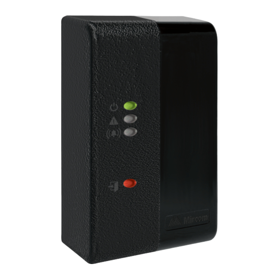
Installation of TX3-CX-1 2.11 Status LEDs Power On: Steady green when controller is on Trouble: Flashes amber to indicate trouble Alarm: Flashes red to indicate alarm Card reader status Green: Door is unlocked Red: Door is locked Figure 20. Status LEDs on TX3-CX-1 Power On. -
Page 28: Rs-485 Addresses
RS-485 Addresses Table 2: DIP Switch Settings for RS-485 Network Addressing ADDRESS SWITCH 1 SWITCH 2 SWITCH 3 SWITCH 4 SWITCH 5 SWITCH 6 TX3-CX-1 Installation Manual Version 1.1 LT-6618 Copyright 2019... - Page 29 RS-485 Addresses Table 2: DIP Switch Settings for RS-485 Network Addressing (Continued) ADDRESS SWITCH 1 SWITCH 2 SWITCH 3 SWITCH 4 SWITCH 5 SWITCH 6 TX3-CX-1 Installation Manual Version 1.1 LT-6618 Copyright 2019...
- Page 30 RS-485 Addresses Table 2: DIP Switch Settings for RS-485 Network Addressing (Continued) ADDRESS SWITCH 1 SWITCH 2 SWITCH 3 SWITCH 4 SWITCH 5 SWITCH 6 TX3-CX-1 Installation Manual Version 1.1 LT-6618 Copyright 2019...
-
Page 31: Specifications
Specifications Standards UL 294 Sixth Edition Performance Levels Feature Access Control Performance Level Destructive Level 1 - No attack test Attack Line Security Level 1 - No line security Endurance Level IV - 100,000 cycles of operation Standby Power Level 1 - No secondary power source Power 3 input power options: •... - Page 32 Specifications Connections • 1 Ethernet 10/100 port with PoE • 1 micro USB port for configuration • 1 RS-485 port Note: To comply with UL 294, do not connect devices to the RS-485 port) • 1 Wiegand connection for optional reader •...
-
Page 33: Warranty And Warning Information
Mircom System and shall be read in conjunction with: the product manual for the specific Mircom System that applies in given circumstances; legal documents that apply to the purchase and sale of a Mircom System, which may include the company’s standard terms and conditions and warranty statements;... - Page 34 Best practices and local authority having jurisdiction determine the frequency and type of testing that is required at a minimum. Mircom System may not function properly, and the occurrence of other system failures identified below may not be minimized, if the periodic testing and maintenance of Mircom Systems is not completed with diligence and as required.
- Page 35 Battery Failure. If the Mircom System or any device connected to the system operates from batteries it is possible for the batteries to fail. Even if the batteries have not failed, they must be fully charged, in good condition, and installed correctly.
- Page 36 Integrated Products. Mircom System might not function as intended if it is connected to a non-Mircom product or to a Mircom product that is deemed non-compatible with a particular Mircom System. A list of compatible products can be requested and obtained.
- Page 37 Warranty and Warning Information Warranty Purchase of all Mircom products is governed by: https://www.mircom.com/product-warranty https://www.mircom.com/purchase-terms-and-conditions https://www.mircom.com/software-license-terms-and-conditions TX3-CX-1 Installation Manual Version 1.1 LT-6618 Copyright 2019...
Need help?
Do you have a question about the TX3 Series and is the answer not in the manual?
Questions and answers