Table of Contents
Advertisement
Available languages
Available languages
Quick Links
ANLEITUNG FÜR EINBAU, BETRIEB UND WARTUNG
KESSEL-Schaltgerät Pumpfix / Ecolift
Installation
der Anlage wurde durchgeführt von Ihrem Fachbetrieb:
Name/Unterschrift
Stand 2019/04
Inbetriebnahme
Datum
Einweisung
Ort
Produktvorteile
Steckerfertige Anschlüsse
Mehrzeilige
Displayanzeige, intuitive
Menüführung
Selbstdiagnosesystem
Wartungsintervall mit
Erinnerung
USB-Schnittstelle
Optional: GSM-
Schnittstelle
Stempel Fachbetrieb
D
Seite 1
GB
Page 29
F
Page 57
I
Pagina 84
NL Pagina 112
PL Strona 140
Sach-Nr. 016-004
Advertisement
Chapters
Table of Contents

Subscribe to Our Youtube Channel
Related Manuals for Kessel Comfort


Summary of Contents for Kessel Comfort
- Page 1 ANLEITUNG FÜR EINBAU, BETRIEB UND WARTUNG Seite 1 KESSEL-Schaltgerät Pumpfix / Ecolift Page 29 Page 57 Pagina 84 NL Pagina 112 PL Strona 140 Produktvorteile Steckerfertige Anschlüsse Mehrzeilige Displayanzeige, intuitive Menüführung Selbstdiagnosesystem Wartungsintervall mit Erinnerung USB-Schnittstelle Optional: GSM- Schnittstelle Installation...
-
Page 3: Table Of Contents
Inhaltsverzeichnis Allgemeines Einleitung und Begrüßung ............................4 Produktbeschreibung, allgemein ........................4 1.2.1 Typenschild ..................................5 1.2.2 Lieferumfang ................................5 Allgemeine Hinweise zu dieser Betriebs- und Wartungsanleitung ............6 Baugruppen, Funktionselemente und Anschlüsse ..................6 1.4.1 Display und Bedienfeld, Anzeigen ........................7 Sicherheit Bestimmungsgemäße Verwendung ........................8 Personalauswahl und -qualifikation ........................8 Organisatorische Sicherheits-Maßnahmen .....................8 Gefahren, die vom Produkt ausgehen .......................8 Montage... - Page 4 5.5.2 Handbetrieb Rückstauklappe ..........................18 Bedienmenü ................................19 Kabellängen anpassen, Software Update Anschlusskabel Pumpe / Sensor kürzen oder verlängern ................22 Update und Daten auslesen ..........................22 6.2.1 Daten auslesen ................................23 6.2.2 Software Update durchführen ..........................23 6.2.3 Parameter einlesen ..............................23 USB Anschluss herausführen ..........................23 Fehlersuche Technische Daten Zusatzfunktionen ..............................25...
-
Page 5: Allgemeines
Haben Sie Fragen? Wir freuen uns auf Ihre Kontaktaufnahme. Produktbeschreibung, allgemein Das Schaltgerät Pumpfix / Ecolift (nachfolgend Schaltgerät genannt) stellt die Steuerung einer KESSEL- Rückstaupumpanlage mit integrierter Pumpe und einer Rückstauklappe mit motorischer Verriegelung dar. Die Schaltsignale der Niveausensoren für den Abwasserpegel werden elektronisch verarbeitet. Als Niveausensoren werden optische Sonden verwendet. -
Page 6: Typenschild
Abb. [1] 1.2.2 Lieferumfang Schaltgerät Betriebs- und Wartungsanleitung Anschlussplan, im Gehäusedeckel des Schaltgerätes Befestigungsmaterial Bohrschablone Optional Externer Signalgeber (Art.Nr. 20162) USB-Gehäusebuchse (Art.Nr. 28785) Kessel TeleControl Modem (Art.Nr. 28792) Abb. [2] Freischaltcode für potentialfreien Kontakt (Art.Nr. 80077) 6 / 168 2019/04... -
Page 7: Allgemeine Hinweise Zu Dieser Betriebs- Und Wartungsanleitung
Allgemeines Allgemeine Hinweise zu dieser Betriebs- und Wartungsanleitung Verwendete Symbole und Legenden <1> Hinweis im Text auf eine Legendennummer in einer Abbildung Bezug auf eine Abbildung • Arbeitsschritt Aufzählung Kursiv Kursive Schriftdarstellung: Bezug zu einem Abschnitt / Punkt im Steuerungs-Menü VORSICHT: Warnt vor einer Gefährdung von Personen und Material. -
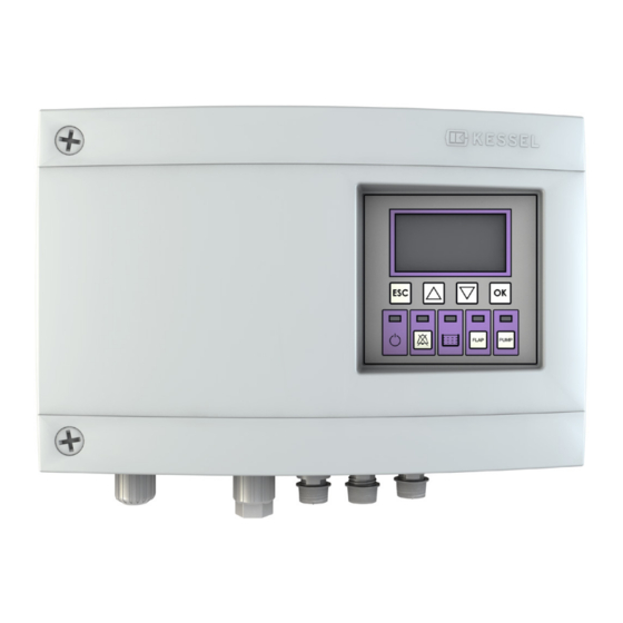
Page 8: Display Und Bedienfeld, Anzeigen
– Im Menü eine Ebene höher – Bestätigen/Auswahl einer Eingabe/Menüpunkt – Cursor eine Position nach rechts * Drucktaster ** Nach 1 Minute wird automatisch wieder der Automatikbetrieb 123-45 aktiviert Pumfpix/Ecolift Pumpifx/Ecolift Comfort Systeminfos: OK Taste FLAP PUMP Abb. [4] 8 / 168 2019/04... -
Page 9: Sicherheit
Sicherheit Sicherheit Bestimmungsgemäße Verwendung Das Schaltgerät ist ausschließlich für die Steuerung von Rückstaupumpanlagen für fäkalienfreies und fäkalienhaltiges* Abwasser zu verwenden. Ein Einsatz des Schaltgeräts in explosionsgefährdeter Umgebung ist unzulässig. Alle nicht durch eine ausdrückliche und schriftliche Freigabe des Herstellers erfolgten –... -
Page 10: Montage
Montage Montage Schaltgerät befestigen Sicherstellen, dass das Schaltgerät während den Montagearbeiten von der Spannungsversorgung getrennt ist. • Montageposition wählen, dabei folgendes sicherstellen: – Eine Schutzkontaktsteckdose befindet sich in unmittelbarer Nähe zum Schaltgeräte. – Die Anschlusskabel von Abwasserpumpe, Rückstauklappe und Niveausensoren können fachgerecht installiert und bis zum Schaltgerät geführt werden. -
Page 11: Usb-Anschluss Herausführen
Montage USB-Anschluss herausführen (Option) • Wenn vorgesehen, den USB-Anschluss herausführen. Dabei verfahren, wie in der dieser Erweiterung beiliegenden Anleitung beschrieben. Abb. [7] 2019/04 11 / 168... -
Page 12: Steckverbindungen Anschlusskabel Herstellen
Montage Steckverbindungen Anschlusskabel herstellen Gefahr durch falsch dimensionierte Anschlussleitungen. Der Pumpfix/Ecolift ist auschließlich für den Betrieb mit den mitgelieferten Anschlussleitungen (oder gleichwertig) vorgesehen. Im Zweifelsfall mit Hersteller / Lieferant Rücksprache nehmen. Achtung, Gefahr durch elektrischen Strom bei unbefugtem Öffnen eines Steckers während dem Betrieb durch z.B. Kinder! Die Befestigungsmutter des Steckers muss so fest angezogen werden, dass Kinder sie nicht öffnen können. - Page 13 Montage Die Kabel der Abwasserpumpen oder der Niveausensoren können verlängert oder gekürzt werden. Siehe hierzu Kapitel 6. • Stecker der Kabelverbindung der Abwasserpumpe am Anschluss <4> anschließen • Stecker Niveausensor (optische Sonde, für das Einschalten der Abwasserpumpe, hausseitig) am Anschluss <1> anschließen •...
- Page 14 Montage Variante Pumpfix Abb. [10] Variante Ecolift Abb. [11] 14 / 168 2019/04...
-
Page 15: Potentialfreien Kontakt Anschließen
Montage 3.3.1 Potentialfreien Kontakt anschließen (Option) • Adernendhülsen (Länge 8 mm) an den Kabelenden anbringen • Anschlusskabel gemäß Anschlussplan an der Klemmleiste befestigen. Dazu mit einem geeigneten Schraubendreher die jeweilige Kabelklemme <3> gegen den Federdruck hinuntergedrückt halten, bis das Kabelende hineingesteckt ist •... -
Page 16: Erstinbetriebnahme
Erstinbetriebnahme Erstinbetriebnahme Ein Trockenlauf der Pumpe ist unbedingt zu vermeiden. Tipp: Beim Herstellen der Netzspannung den Netzstecker sofort wieder ausstecken, wenn die Abwasserpumpe unbeabsichtigt eingeschaltet wird (z. B. bei einem defekten Niveausensor). Beschreibung des Bedienschemas siehe 5.6 Bei der Erstinbetriebnahme werden folgende Eingaben erwartet: 1. -
Page 17: Selbstdiagnoseintervall Ändern
Einen Alarmzustand (Alarm-LED blinkt) herstellen und damit sicherstellen, dass das Signal am potentialfreien Kontakt erkennbar ist. Hierzu Netzspannung abschalten, Alarmzustand ist hergestellt, Funktion kann überprüft werden SMS-Alarmierung aktivieren • Verfahren, wie in der diesem Zubehör (Kessel TeleControl Modem) beiliegenden Anleitung beschrieben Funktionsprüfung durchführen • Sicherstellen, dass im Display keine Fehlermeldung anliegt •... -
Page 18: Betrieb
Betrieb Betrieb Einschalten • Spannungsversorgung herstellen – Das Schaltgerät führt einen Selbsttest durch. – Im Display wird der in der Anlagenkonfiguration eingestellte Gerätetyp angezeigt. – Sofern kein Systemfehler, Alarm oder erhöhtes Abwasserniveau erkannt wurde - leuchtet die grüne Betriebsbereit-LED <19> (siehe Abb. [4]). –... -
Page 19: Alarmmeldung Bei Netzausfall
Betrieb Alarmmeldung bei Netzausfall Ein Netzausfall wird durch die Batterieversorgung des Schaltgerätes erkannt und wie folgt dargestellt: – Akustischer Alarm (kurzes Signal, ca. alle 20 Sekunden) – Displayanzeige: Netzausfall – Entsprechend dem Fehlerbild blinken (im gleichen Intervall wie der akustische Alarm) eine oder mehrere LED‘s: PUMP PUMP... -
Page 20: Handbetrieb Allgemein
Betrieb Handbetrieb allgemein Im Handbetrieb kann folgendes durchgeführt werden: – Abwasserpumpe EIN- / AUS – Rückstauklappe in Position AUF / ZU bewegen 5.5.1 Handbetrieb Abwasserpumpe 1. Handbetrieb aktivieren • Taste Pumpe <26> betätigen, die LED Pumpe <23> blinkt, Nun findet kein automatisches Einschalten der Abwasserpumpe mehr statt. Wird der Handbetrieb während dem Abpumpen eingeschaltet, schaltet das die Abwasserpumpe aus. -
Page 21: Bedienmenü
Betrieb Rückstauklappe im Handbetrieb öffnen Nur möglich, wenn die Rückstauklappe im Handbetrieb geschlossen wurde und kein Rückstau anliegt (LED Rückstauklappe <22> leuchtet). • Taste Rückstauklappe <25> betätigen, die Rückstauklappe wird von der Position ZU in die Position AUF bewegt. Während der Positionsänderung blinkt die LED Rückstauklappe <22>. Die Rückstauklappe ist geöffnet, wenn die LED Rückstauklappe <22>... - Page 22 Betrieb Menüstruktur Systeminfo Informationen Betriebsstunden 1.1.1 Gesamtlaufzeit 1.1.2 Netzausfall 1.1.3 Energieverbrauch 1.1.4 Rückstauzeit 1.1.5 Rückstauanzahl 1.1.6 Schaltspiele Klappe 1.1.7 Laufzeit Pumpe 1.1.8 Schaltsp.Pumpe 1.1.9 Überspannung 1.1.10 Unterspannung Logbuch Steuerungstyp Wartungstermin 1.4.1 Letzte Wartung 1.4.2 Nächste Wartung akt. Messwerte 1.5.1 Batterie-Spannung 1.5.2 Netz-Spannung 1.5.3...
- Page 23 Betrieb 2.6.3 6 Monate 2.6.4 12 Monate 2.6.5 Manuelle Wartung Einstellungen Parameter 3.1.1 SDS-Selbstdiagnosesystem 3.1.2 Einschaltverzögerung Klappe 3.1.3 Nachlaufzeit Klappe 3.1.4 Max. Strom Klappe 3.1.5 Einschaltverzögerung Pumpe 3.1.6 Nachlaufzeit Pumpe 3.1.7 Max. Strom Pumpe 3.1.8 Min. Strom Pumpe 3.1.9 Grenzlaufzahl Pumpe 3.1.10 Grenzlaufzeit Pumpe 3.1.16...
-
Page 24: Kabellängen Anpassen, Software Update
Kabellängen anpassen, Software Update Kabellängen anpassen, Software Update Achtung, Gefahr durch elektrischen Strom! Nachstehend beschriebe Umrüstungen dürfen ausschließlich durch autorisiertes Elektrofachpersonal durchgeführt werden (siehe 2.2, Personalauswahl und -qualifikation). Anschlusskabel Pumpe / Sensor kürzen oder verlängern Bestellbare Verlängerungen (Länge 10m) – Art.-Nr. -
Page 25: Daten Auslesen
USB Anschluss herausführen Damit der auf der Platine befindliche USB-Anschluss ohne ein Öffnen des Gehäuses zugängig wird, kann eine USB-Gehäusebuchse mit Kabel und Stecker zum Einbau in das Gehäuse des Schaltgerätes bei KESSEL bestellt werden (siehe 1.2.2). 2019/04 25 / 168... -
Page 26: Fehlersuche
Fehlersuche Fehlersuche Achtung, Beim Öffnen des Schaltgerätegehäuses besteht Gefahr vor elektrischer Spannung. Arbeiten an elektrischen Bauteilen dürfen nur von Fachpersonal (Siehe 2.2) durchgeführt werden. Fehler Ursache Abstellmaßnahme Batteriefehler Batterie fehlt, ist defekt oder Spannung zu gering Netzstecker ziehen, Batterien anschließen, ggf. durch neue Batterien ersetzen. -
Page 27: Technische Daten
Technische Daten Technische Daten Betriebsspannung [V] 50 Hz Stromleistung [W] Einsatz 1200 Stromleistung [W] Standby Schutzart IP54 Schutzklasse Steckertyp Schutzkontaktstecker Einsatztemperatur Schaltgerät 0°C bis + 50°C Anschlusskabel [m] Gewicht ca. [kg] Erforderliche Absicherung FI-Schutzschalter Sicherungsautomat C 16A 1 pol. Wenn USB-Anschluss montiert: Nur gewährleistet, wenn Schutzkappe auf USB-Anschluss aufgesteckt 294 mm 194 mm 272 mm... -
Page 28: Konformitätserklärung
Konformitätserklärung Konformitätserklärung 28 / 168 2019/04... - Page 29 INSTRUCTIONS FOR INSTALLATION, OPERATION AND MAINTENANCE KESSEL Pumpfix / Ecolift control unit Product advantages Plug&play connections Multi-line display, intuitive menu guidance Self-diagnosis system Maintenance interval with reminder USB interface Optional: GSM interface Installation Putting into operation Instructional briefing for the system was carried out by your specialist...
- Page 30 Table of contents General information Introduction and greeting............................32 Product description, general ..........................32 1.2.1 Type plate ................................33 1.2.2 Scope of delivery ..............................33 General instructions on using these operating and maintenance instructions .........34 Assemblies, functional elements and connections ..................34 1.4.1 Display and control panel ..........................35 Safety Correct use ...................................36 Staff selection and qualification ...........................36...
- Page 31 Adapting cable lengths, software update Shortening or lengthening the pump/sensor connection cable .............51 Update and reading out data ..........................51 6.2.1 Read out data ................................52 6.2.2 Carry out software update ..........................52 6.2.3 Read in parameters ..............................52 Routing the USB connection out .........................52 Troubleshooting Technical data Additional functions ..............................54...
-
Page 32: General Information
Product description, general The Pumpfix / Ecolift control unit (hereinafter referred to as the control unit) is the control unit for a KESSEL backwater pumping station with integrated pump and a backwater flap locked by a motor. The level sensor switching signals for the wastewater level are processed electronically. -
Page 33: Type Plate
Connection diagram, in the control unit housing cover Fastening material Drilling template Optional Ext. signal generator (art. # 20162) USB housing socket (art. # 28785) Kessel TeleControl modem (art. # 28792) Fig. [2] Clearance code for potential-free contact (art. # 80077) 2019/04 33 / 168... -
Page 34: General Instructions On Using These Operating And Maintenance Instructions
General instructions on using these operating and maintenance instructions Symbols and legends used <1> Reference in the text to a legend number in an illustration Reference to an illustration • Working step List Italics Italic case design: Reference to a section / item in the control menu CAUTION: Warns of a risk to persons and material. -
Page 35: Display And Control Panel
– One level higher in a menu – Confirm/select an input/menu item – Move cursor one position to the right * Push-button ** The automatic mode is automatically re-activated 123-45 activated Pumfpix/Ecolift Pumpifx/Ecolift Comfort Systeminfos: OK Taste FLAP PUMP Fig. [4] 2019/04 35 / 168... -
Page 36: Safety
Safety Correct use The control unit may only be used to control backwater valves of the type FKA for wastewater with or without sewage. The control unit must not be used in a potentially explosive environment. – conversions or attachments –... -
Page 37: Installation
Installation Fastening the control unit Make sure that the control unit is disconnected from the power supply during installation work. • Select the mounting position making sure that: – there is a safety socket in the direct vicinity of the control units. –... -
Page 38: Routing The Usb Connection Out
Routing the USB connection out (Option) • Route the USB connection out, if provided. To do so, proceed as described in the instructions included with this extension. Fig. [7] 38 / 168 2019/04... -
Page 39: Connecting The Plug-Type Connections To The Connecting Cable
Connecting the plug-type connections to the connecting cable Danger through incorrectly dimensioned connection cables. The Pumpfix/Ecolift is only designed for operation with the enclosed connection cables (or equivalent). If in doubt, consult the manufacturer / supplier. Beware of the risk through electric current if a plug is opened without authorisation during operation e.g. through children. - Page 40 The cables of the pumps or the optical probes can be lengthened or shortened. See chapter 6.1 Shortening or lengthening the motor / sensor cable • Connect the plug for the wastewater pump’s cable connection to connection <4> • Connect the level sensor’s plug (optical probe, to switch on the wastewater pump on the house side) to connection <1>...
- Page 41 Pumpfix version Fig. [10] Ecolift version Fig. [11] 2019/04 41 / 168...
-
Page 42: Connect The Potential-Free Contact
3.3.1 Connect the potential-free contact (Option) • Fit end sleeves (length 8 mm) to the ends of the cables • Attach connecting cable to the terminal strip acc. to the circuit diagram To do so, keep the relevant cable terminal <3> pressed down against the spring pressure with a suitable screwdriver until the end of the cable has been inserted •... -
Page 43: Initial Operation
Initial operation Dry running of the pump must be avoided at all costs. Tip: When connecting to the mains, disconnect the mains plug immediately if the wastewater pump is switched on accidentally (e. g. by a faulty level sensor). See 5.6 for a description of the control panel During commissioning, the following input is expected: 1. -
Page 44: Changing Self-Diagnosis Interval
To do so, switch off the mains voltage, alarm status is established, the function can be checked Activate SMS alerting • Proceed as described in the instructions included with this accessory (Kessel TeleControl Modem). Carrying out a functional check • Make sure that no error message is pending in the display •... -
Page 45: Operation
Operation Switching on • Set up the voltage supply – The control unit performs a self-test. – The display shows the device type set in the system configuration. – If no system error, alarm or increased wastewater level is detected - the green ready for operation LED comes on <19>... -
Page 46: Alarm Message In The Event Of A Power Outage
Alarm message in the event of a power outage A power outage is detected by the control unit’s battery supply and shown as follows: – Acoustic alarm (short signal, approx. every 20 seconds) – Display: Power outage – One or more LEDs flash according to the fault pattern (at the same interval as the acoustic alarm) FLAP PUMP FLAP... -
Page 47: Manual Mode, General
Manual mode, general The following can be carried out in the manual mode: – Wastewater pump ON / OFF – Move the backwater flap to the OPEN / CLOSED position 5.5.1 Wastewater pump manual mode 1. Activate manual operation • Press the Pump key <26>, the pump LED <23>... -
Page 48: Operating Menu
Opening the backwater flap in the manual mode Only possible if the backwater flap has been closed in the manual mode and there is no backwater (backwater flap LED <22> is on). • Press the backwater flap key <25>, the backwater flap is moved from the CLOSED to the OPEN position. The backwater flap LED <22>... - Page 49 Menu structure System info Information Hours of operation 1.1.1 Total running time 1.1.2 Power outage 1.1.3 Energy usage 1.1.4 Backwater phase 1.1.5 Backwater occurrences 1.1.6 Operating cycles flap 1.1.7 Run time pump 1.1.8 Op. cycle pump 1.1.9 Overvoltage 1.1.10 Undervoltage Log book Control type Maintenance date...
- Page 50 2.6.4 12 months 2.6.5 Manual maintenance 3.1.1 Settings Parameters SDS Self diagnosis system 3.1.2 On delay flap 3.1.3 Post run time flap 3.1.4 Max. current flap 3.1.5 Switch-on delay pump 3.1.6 Run-on time pump 3.1.7 Max. current pump 3.1.8 Min. current pump 3.1.9 Pump transmitting figure 3.1.10...
-
Page 51: Adapting Cable Lengths, Software Update
Adapting cable lengths, software update Caution, risk caused by electric current! The conversions described below may only be carried out by authorised and qualified electricians (2.2). Shortening or lengthening the pump/sensor connection cable Extensions to be ordered (length 10m) – Art. -
Page 52: Read Out Data
Routing the USB connection out To make the USB socket on the board accessible without the housing having to be opened, a USB housing socket with cable and connector for installation in the control unit housing can be ordered from KESSEL (see 1.2.2). -
Page 53: Troubleshooting
Troubleshooting Caution, risk of electrical voltage when the control unit housing is opened. Work on electrical components may only be carried out by specialist (see 2.2). Error possible cause Remedial measure Battery fault Battery is missing or faulty Remove the mains plug, connect batteries, replace by new batteries if necessary. -
Page 54: Technical Data
Technical data Operating voltage [V] 50 Hz 1400 Power consumption [W] in use Power consumption [W] standby Protective rating IP54 Protective class Plug type Earthed connector Connecting cable [m] Weight ca. [kg] Required fuse protection C 16A 1 pol. Required fuse protection Fault current circuit breaker 294 mm... -
Page 55: Declaration Of Conformity
Fig. [24]Declaration of conformity 2019/04 55 / 168... - Page 56 INSTRUCTIONS DE POSE, D‘UTILISATION ET DE MAINTENANCE Gestionnaire KESSEL Pumpfix / Ecolift Avantages du produit Prêt au raccordement Écran d‘affichage à plusieurs lignes, arborescence intuitive du menu Système d‘autodiagnostic Intervalle de maintenance avec fonction mémoire Port USB Option : interface GSM L‘installation...
- Page 57 Sommaire Généralités Introduction et accueil ............................60 Description générale du produit .........................60 1.2.1 Plaque signalétique .............................61 1.2.2 Détail de livraison ..............................61 Informations d‘ordre général concernant ces instructions d‘utilisation et de maintenance ..62 Composants, éléments fonctionnels et raccordements ................62 1.4.1 Écran et panneau de commande, affichages .....................63 Sécurité...
- Page 58 Adaptation de la longueur des câbles, mise à jour du logiciel Raccourcissement ou rallongement du câble de raccordement de la pompe / du détecteur ..79 Exportation de mises à jour et données......................79 6.2.1 Exportation de données ............................80 6.2.2 Mise à jour du logiciel ............................80 6.2.3 Importation de paramètres ..........................80 Pose du port USB vers l‘extérieur .........................80...
-
Page 59: Généralités
Chère cliente, Cher client, Nous vous félicitons de votre achat d‘un produit KESSEL. Ce produit sera certainement en mesure de répondre à toutes vos attentes. Nous vous souhaitons une mise en place sans faille et réussie. Nous tentons de maintenir un niveau de qualité aussi élevé que possible de nos produits et avons évidemment besoin de votre collaboration. -
Page 60: Plaque Signalétique
Accessoires de montage Gabarit de perçage Option Émetteur de signaux externe (Réf. # 20162) Boîtier à douille USB (Réf. # 28785) Fig. [2] Modem Kessel TeleControl (Réf. # 28792) Code d‘activation du contact sans potentiel (Réf. # 80077) 60 / 168 2019/04... -
Page 61: Informations D'ordre Général Concernant Ces Instructions D'utilisation Et De Maintenance
Informations d‘ordre général concernant ces instructions d‘utilisation et de maintenance Pictogrammes et légendes utilisés <1> Information dans le texte attirant l‘attention sur un numéro de légende dans une figure Renvoi à une figure • Étape opératoire Énumération Italique caractères en italique : renvoi à une section / point dans le menu de commande ATTENTION : avertit d‘un danger corporel et matériel. -
Page 62: Écran Et Panneau De Commande, Affichages
– Confirmation / sélection d’une saisie / d’un point de menu – Déplacement du curseur d’une position vers la droite * Bouton-poussoir ** Le mode automatique est automatiquement réactivé après 123-45 1 minute Pumfpix/Ecolift Pumpifx/Ecolift Comfort Systeminfos: OK Taste FLAP PUMP Fig. [4] 62 / 168 2019/04... -
Page 63: Sécurité
Sécurité Utilisation conforme à l‘usage prévu Le gestionnaire est exclusivement destiné à commander des postes de relevage (DIN EN 12050, partie 1-3) et des clapets anti-retours avec pompe pour eaux grises et eaux-vannes*. L‘utilisation du gestionnaire dans des zones à risque d‘explosion est interdite. Il faut savoir, à... -
Page 64: Montage
Montage Fixation du gestionnaire S’assurer que le gestionnaire a été coupé de l’alimentation en tension pendant les travaux de montage. • Choisir l‘emplacement prévu au montage en veillant aux points suivants : – Proximité directe du gestionnaire d‘une prise secteur avec terre. –... -
Page 65: Pose Du Port Usb Vers L'extérieur
Pose du port USB vers l‘extérieur (Option) • Si prévu, poser le port USB vers l‘extérieur. Procéder comme décrit aux instructions jointes à la présente extension. Ill. [24] 2019/04 65 / 168... -
Page 66: Raccordement Des Connecteurs Et Câbles
Raccordement des connecteurs et câbles Risque dû au dimensionnement erroné des conduites de raccordement. Le Pumpfix/Ecolift est exclusivement prévu pour une utilisation avec les conduites de raccordement fournies (ou des conduites équivalentes). Demander conseil au fabricant / fournisseur en cas de doute. Attention, risque lié... - Page 67 : Il est possible de rallonger ou de raccourcir les câbles du moteur ou des sondes optiques. Voir le chapitre 6.1 Raccourcir ou rallonger les câbles du moteur / de la sonde • Raccorder le connecteur du raccord de câbles de la pompe d‘assainissement au raccord <4>...
- Page 68 Variante Pumpfix Fig. [9] Variante Ecolift Fig. [10] 68 / 168 2019/04...
-
Page 69: Raccordement Du Contact Sans Potentiel
3.3.1 Raccordement du contact sans potentiel (Option) • Monter les manchons de bout pour torons (longueur de 8 mm) aux extrémités des câbles • Fixer le câble de raccordement suivant le schéma de raccordement à la réglette à bornes. Pour ce faire, se servir d‘un tournevis à fente approprié... -
Page 70: Première Mise En Service
Première mise en service Éviter impérativement tout fonctionnement à sec de la pompe. Astuce : Lors de l’établissement de la tension de réseau, retirer immédiatement la fiche de secteur en cas d‘activation inopinée de la pompe d‘assainissement (p. ex. si le détecteur de niveau est défectueux). Description du schéma de commande, vo5.65.6 La première mise en service impose de procéder aux saisies suivantes : 1. -
Page 71: Modification De L'intervalle D'autodiagnostic
Pour se faire, couper la tension d‘alimentation qui a pour effet d’établir l’état d’alarme ; la fonction est vérifiable Activation de l’alarme par textos • Procéder comme décrit aux instructions jointes à cet accessoire (Kessel TeleControl Modem) Contrôle fonctionnel • Vérifier l‘absence d’un message d‘erreur à l’écran •... -
Page 72: Service
Service Mise en circuit • Établir l’alimentation en tension – Le gestionnaire exécute un autodiagnostic. – L‘écran affiche le type d‘appareil paramétré dans la configuration du système. – Si le système fonctionne correctement sans défaut, la diode verte qui signale que l’appareil est en ordre de marche <19>... -
Page 73: Message D'alarme En Cas De Panne De Secteur
Message d‘alarme en cas de panne de secteur Une panne de secteur est identifiée par l’alimentation de la batterie du gestionnaire et signalée comme suit : – Alarme acoustique (bref signal à intervalles d’env. 20 secondes) – Affichage de l‘écran : Panne de secteur –... -
Page 74: Commande Manuelle En Général
Commande manuelle en général La manœuvre suivante est possible par commande manuelle : – Pompe d‘assainissement MARCHE / ARRÊT – Déplacement du clapet anti-retour à la position OUVERTE / FERMÉE 5.5.1 Commande manuelle de la pompe d‘assainissement 1. Activation de la commande manuelle •... -
Page 75: Menu De Commande
Ouverture du clapet anti-retour par commande manuelle Manœuvre uniquement possible si le clapet anti-retour a été fermé par une commande manuelle et en l’absence d’un reflux (la diode du clapet anti-retour <22> brille). • Appuyer sur la touche du clapet anti-retour <25> ; le clapet anti-retour est déplacé de la position FERMÉE sur la position OUVERTE. - Page 76 Arborescence du menu 0. Info système 1. Informations Heures de service 1.1.1 Durée totale 1.1.2 Panne de secteur 1.1.3 Consommation d‘énergie 1.1.4 Durée de la mise en charge 1.1.5 Nombre de mises en charge 1.1.6 Cycles du battant 1.1.7 Durée de marche de la pompe 1.1.8 Point de commutation de la pompe 1.1.9...
- Page 77 2.6.3 6 mois 2.6.4 12 mois 2.6.5 Maintenance manuelle Configurations Paramètres 3.1.1 Système d‘autodiagnostic SDS 3.1.2 Temporisation de mise en circuit du battant 3.1.3 Durée de fonctionnement par inertie du battant 3.1.4 Courant Courant du battant 3.1.5 Temporisation de mise en circuit de la pompe 3.1.6 Fonctionnement par inertie de la pompe 3.1.7...
-
Page 78: Adaptation De La Longueur Des Câbles, Mise À Jour Du Logiciel
Adaptation de la longueur des câbles, mise à jour du logiciel Attention au danger lié au courant électrique ! Les rééquipements décrits ci-après demeurent réservés au domaine de compétence exclusif d’électriciens agréés (voir 2.2). Raccourcissement ou rallongement du câble de raccordement de la pompe / du détecteur Rallonges disponibles (longueur de 10 m) –... -
Page 79: Exportation De Données
Afin que le port USB situé sur la platine soit aussi accessible sans l‘ouverture du boîtier, il est possible de commander un boîtier à douille USB, équipé d‘un câble et d‘un connecteur à intégrer dans le boîtier du gestionnaire chez KESSEL (voir 1.2.2). 2019/04... -
Page 80: Aide Au Diagnostic
Aide au diagnostic Attention : danger de tension électrique en ouvrant le boîtier du gestionnaire. Les travaux sur les composants électriques demeurent réservés au domaine de compétence d‘électriciens qualifiés (voir 2.2). Affichage des pannes Cause Mesure d’arrêt Panne de batterie La batterie manque ou est défectueuse Retirer la fiche de secteur, connecter les batteries, si nécessaire les remplacer par de nouvelles batteries. -
Page 81: Caractéristiques Techniques
Caractéristiques techniques Tension de service [V] 50 Hz Consommation d‘énergie [W] en 1400 fonctionnement Consommation d‘énergie [W] en veille Type de protection IP54 Catégorie de protection Type de connecteur Prise secteur avec terre Câble de raccordement [m] Poids approximatif [kg] Protection par fusible nécessaire Interrupteur de protection contre les courants de surcharge... -
Page 82: Déclaration De Conformité
Déclaration de conformité 82 / 168 2019/04... - Page 83 ISTRUZIONI PER L‘INSTALLAZIONE, IL FUNZIONAMENTO E LA MANUTENZIONE Centralina KESSEL Pumpfix / Ecolift Vantaggi del prodotto Collegamenti pronti per l’uso Visualizzazione display a più righe, guida a menu intuitiva Sistema di auto- diagnostica Intervallo di manutenzione con avviso Interfaccia USB Opzionale: un‘interfaccia...
- Page 84 Indice Informazioni generali Introduzione e saluto ...............................87 Descrizione del prodotto, in generale........................87 1.2.1 Targhetta .................................88 1.2.2 In dotazione ................................88 Indicazioni generali sulle presenti istruzioni per l’uso e la manutenzione ...........89 Gruppi costruttivi, elementi funzionali e collegamenti ................89 1.4.1 Display e quadro di comando, visualizzazioni ...................90 Sicurezza Uso conforme alla destinazione ...........................91 Scelta e qualifica del personale ..........................91...
- Page 85 Adattamento lunghezza cavi, aggiornamento software Accorciamento o allungamento del cavo di collegamento della pompa/sensore ......106 Aggiornamento e lettura dei dati ........................106 6.2.1 Lettura dati ................................107 6.2.2 Esecuzione dell’aggiornamento del software ...................107 6.2.3 Inserimento parametri ............................107 Estrazione del collegamento USB ........................107 Ricerca di errori Dati tecnici Funzioni addizionali..............................110...
-
Page 86: Informazioni Generali
La centralina Pumpfix / Ecolift (di seguito centralina) costituisce il comando di una valvola di non ritorno KESSEL con sistema di pompaggio, pompa integrata e clapet antiriflusso con chiusura motorizzata. I segnali di commutazione dei sensori delle acque di scarico vengono elaborati elettronicamente. Come sensori di livello vengono utilizzate sonde ottiche. -
Page 87: Targhetta
Materiale di fissaggio Mascherina per la realizzazione dei fori optional Generatore esterno di segnali (cod.art. 20162) Presa USB (cod.art. 28785) Modem di telecomando Kessel (cod.art. 28792) Codice di abilitazione per contatto a potenziale zero (cod.art. Fig. [2] 80077) 2019/04 87 / 168... -
Page 88: Indicazioni Generali Sulle Presenti Istruzioni Per L'uso E La Manutenzione
Indicazioni generali sulle presenti istruzioni per l’uso e la manutenzione Simboli utilizzati e legenda <1> Riferimento nel testo ad un numero di legenda in un‘immagine Riferimento ad una figura • Passo di lavoro Numerazione Corsivo Scritta in corsivo: riferimento a una sezione / un punto nel menu di comando PRUDENZA: avverte circa un pericolo per le persone ed il materiale. -
Page 89: Display E Quadro Di Comando, Visualizzazioni
– Conferma/selezione di una immissione/opzione del menu – Cursore una posizione più a destra * Pulsante ** Dopo 1 minuto, la modalità di funzionamento automatica viene di 123-45 nuovo attivato Pumfpix/Ecolift Pumpifx/Ecolift Comfort Systeminfos: OK Taste FLAP PUMP Fig. [4] 2019/04 89 / 168... -
Page 90: Sicurezza
Sicurezza Uso conforme alla destinazione La centralina si deve utilizzare esclusivamente per comandare valvole di non ritorno con sistema di pompaggio per acque di scarico contenenti sostanze fecali o meno. Un impiego della centralina negli ambienti a rischio di esplosione non è ammesso. In assenza di un‘autorizzazione espressa e in forma scritta da parte del produttore, –... -
Page 91: Montaggio
Montaggio Fissare la centralina Accertare che la centralina sia separato dall’alimentazione di tensione durante i lavori di montaggio. • Scegliere la posizione di montaggio accertando che: – Una presa con contatto di terra si trovi nelle immediate vicinanze della centralina. –... -
Page 92: Estrazione Del Collegamento Usb
Estrazione del collegamento USB (Opzionale) • Se prevista, estrarre il collegamento USB. Procedere come descritto nelle istruzioni allegate a questo ampliamento. Fig. [7] 92 / 168 2019/04... -
Page 93: Esecuzione Collegamenti A Spina Cavo Di Collegamento
Esecuzione collegamenti a spina cavo di collegamento Pericolo a causa del dimensionamento errato dei condotti di collegamento. Il Pumpfix/Ecolift è destinato esclusivamente al funzionamento con le condotte di collegamento in dotazione (o analoghe). In caso di dubbio contattare il produttore / fornitore. Attenzione, pericolo causato dalla corrente elettrica in caso di apertura non autorizzata di un connettore durante il funzionamento, ad esempio da parte di di bambini! Il dado di fissaggio del connettore deve essere serrato saldamente, in modo da non poter essere allentato dai bambini. - Page 94 I cavi del pompa o le sonde ottiche si possono allungare o accorciare. Vedere a tale fine il capitolo 6.1 Accorciamento o allungamento del motore / sensore. • Collegare la spina di collegamento del cavo della pompa di scarico acqua con il collegamento <4>...
- Page 95 Variante Pumpfix Fig. [10] Variante Ecolift Fig. [11] 2019/04 95 / 168...
-
Page 96: Collegamento Del Contatto A Potenziale Zero
3.3.1 Collegamento del contatto a potenziale zero (Opzionale) • Applicare i capicorda (lunghezza di 8 mm) alle estremità dei cavi. • Fissare il cavo di collegamento come indicato sullo scheda di collegamento accanto alla morsettiera. A tale fine, tenere premuto il rispettivo morsetto per cavo <3>... -
Page 97: Prima Messa In Funzione
Prima messa in funzione Il funzionamento a secco della pompa deve essere assolutamente evitato. Suggerimento: Al ripristino della tensione di rete si deve staccare subito la spina se la pompa delle acque di scarico viene inserita involontariamente (ad es. in caso di guasto al sensore di livello). Per la descrizione dello schema di co5.6do, vedi 5.6 Al momento della prima messa in funzione vengono richieste le seguenti immissioni: 1. -
Page 98: Modificare L'intervallo Di Auto-Diagnostica
Opzionale: accertarsi che quanto segue funzioni correttamente • Contatto a potenziale zero • Allarme SMS (modem di telecomando Kessel) • Generatore di segnali esterno Quando tutti i punti rilevanti sono stati eseguiti, la centralina è pronto a funzionare 98 / 168... -
Page 99: Funzionamento
Funzionamento Accensione • Inserire la tensione di alimentazione – La centralina esegue l‘autotest. – Sul display viene indicato il tipo di apparecchio impostato nella configurazione dell’impianto. – Il LED verde di prontezza al funzionamento <19> (vedere Fig. [14]) si illumina se non sono stati identificati errori di sistema. -
Page 100: Segnalazione Di Allarme In Caso Di Guasto Della Rete Elettrica
Segnalazione di allarme in caso di guasto della rete elettrica Un eventuale blackout viene rilevato dall‘alimentazione a batteria della centralina e indicato come segue: – Allarme acustico (breve segnale, all‘incirca ogni 20 secondi) – Display: Guasto alla rete elettrica – A seconda della rappresentazione dell‘errore, lampeggiano (con lo stesso intervallo dell‘allarme acustico) uno o più... -
Page 101: Funzionamento Manuale Generale
Funzionamento manuale generale In modalità di funzionamento manuale si può eseguire quanto segue: – Pompa di scarico acqua ON/OFF – portare il clapet antiriflusso in posizione Aperto/Chiuso 5.5.1 Modalità manuale pompa di scarico acqua 1. Attivazione del funzionamento manuale • Azionare il tasto Pompa <26>, il LED Pompa <23>... -
Page 102: Menu Di Comando
Aprire il clapet antiriflusso in modalità di funzionamento manuale Possibile solo se il clapet antiriflusso era stato chiuso in modalità di funzionamento manuale e non c’è alcun ristagno (LED Clapet antiriflusso <22> acceso). • Azionare il tasto Clapet antiriflusso <25>, il clapet antiriflusso si porta dalla posizione Chiuso alla posizione Aperto. - Page 103 Struttura del menu Info di sistema Informazioni Ore di funzionamento 1.1.1 Tempo di funzionamento complessivo 1.1.2 Guasto alla rete elettrica 1.1.3 Consumo energetico 1.1.4 Tempo del ristagno 1.1.5 Numero di ristagni 1.1.6 di commutazione max della cerniera 1.1.7 Tempo di funzionamento della pompa 1.1.8 Tens.
- Page 104 2.6.2 3 mesi 2.6.3 6 mesi 2.6.4 12 mesi 2.6.5 Manutenzione manuale 3.1.1 Impostazioni Parametri Sistema di auto-diagnostica SDS 3.1.2 Ritardo di accensione della cerniera 3.1.3 Durata di funzionamento dopo lo spegnimento della cerniera 3.1.4 Corrente max della cerniera 3.1.5 Ritardo di accensione pompa 3.1.6 Durante di funzionamento dopo lo spegnimento...
-
Page 105: Adattamento Lunghezza Cavi, Aggiornamento Software
Adattamento lunghezza cavi, aggiornamento software Attenzione, pericolo causato dalla corrente elettrica! I riallestimenti di seguito descritti devono essere eseguiti esclusivamente da personale elettrico autorizzato (vedi 2.2) Accorciamento o allungamento del cavo di collegamento della pompa/sensore Prolunghe ordinabili (lunghezza 10 m) –... -
Page 106: Lettura Dati
Estrazione del collegamento USB Per fare in modo che il collegamento USB presente sul circuito stampato sia accessibile senza dover aprire l‘alloggiamento è possibile ordinare presso KESSEL una presa USB per l‘alloggiamento con cavo e connettore per l‘inst1.2.2ione nell‘alloggiamento della centralina (vedi 1.2.2). -
Page 107: Ricerca Di Errori
Ricerca di errori Attenzione! Quando si apre l‘alloggiamento della centralina si rischia di subire folgorazioni per la tensione elettrica presente. I lavori agli elementi elettrici devono essere eseguiti solo da persone specializzato (vedere Anomalie Causa Rimedio Anomalia batteria Batteria mancante o difettosa Staccare la spina, collegare le batterie, eventualmente sostituire con nuove. - Page 108 Anomalia sonda IInizializzazione: linea controllo Staccare la spina, disattivare la batteria; controllare se la linea di “Sonda” non collegata, interrotta controllo è collegata correttamente e non è interrotta; eventualmente o polarità invertita Durante il sostituire la sonda funzionamento: linea di controllo “Sonda”...
-
Page 109: Dati Tecnici
Dati tecnici Tensione di funzionamento [V] 50 Hz Consumo di corrente [W] impiego 1400 Consumo di corrente [W] standby Tipo di protezione IP54 Classe di protezione Tipo di connettore Connettore Schuko Cavo di collegamento [m] Peso ca. [kg] Protezione necessaria Salvavita Protezione necessaria C 16 A 1 pol. -
Page 110: Dichiarazione Di Conformità
Dichiarazione di conformità 110 / 168 2019/04... - Page 111 HANDLEIDING VOOR DE INBOUW, HET GEBRUIK EN HET ONDERHOUD KESSEL-besturingskast Pumpfix / Ecolift Productvoordelen Direct aansluitbare aansluitingen Display-indicatie over verschillende regels, intuïtieve menubesturing Zelfdiagnosesysteem Onderhoudsinterval met herinnering USB-interface Optioneel GSM-interface Installatie Inbedrijfstelling Instructie van de installatie werd uitgevoerd door uw gespecialiseerd...
- Page 112 Inhoudsopgave Algemeen Inleiding en begroeting ............................115 Productomschrijving, algemeen ..........................115 1.2.1 Typeplaatje ................................116 1.2.2 Leveringsomvang ..............................116 Algemene instructies bij deze gebruiks- en onderhoudshandleiding ..........117 Modules, functie-elementen en aansluitingen ....................117 1.4.1 Display en besturingspaneel, indicaties ......................118 Veiligheid Voorgeschreven gebruik ............................119 Personeelskeuze en -kwalificatie .........................119 Organisatorische veiligheidsmaatregelen .......................119 Gevaren die uitgaan van het product ........................119 Montage...
- Page 113 6.2.1 Gegevens uitlezen ...............................135 6.2.2 Software update uitvoeren ..........................135 6.2.3 Parameter inlezen ..............................135 USB-aansluiting naar buiten voeren ........................135 Opsporen van storingen Technische gegevens Extra functies ................................138 Conformiteitsverklaring 2019/04 113 / 168...
-
Page 114: Algemeen
Hebt u vragen? Wij zien ernaar uit dat u contact opneemt. Productomschrijving, algemeen De besturingskast Pumpfix / Ecolift (hierna besturingskast genoemd) vormt de besturing van een KESSEL- terugstuwpompinstallatie met geïntegreerde pomp en een terugstuwklep met motorische vergrendeling. De schakelsignalen van de niveausensoren voor het afvalwaterpeil worden elektronisch verwerkt. Als niveausensoren worden optische sonden gebruikt. -
Page 115: Typeplaatje
Bedrijfs- en onderhoudshandleiding Aansluitschema, in het deksel van de omkasting van de besturingskast Bevestigingsmateriaal Boorsjabloon Optioneel Externe signaalgenerator (art. nr. 20162) USB-behuizingsbus (art. nr. 28785) Kessel TeleControl modem (art.nr. 28792) Vrijschakelcode voor potentiaalvrij contact (art.nr. 80077) Afb. [2] 2019/04 115 / 168... -
Page 116: Algemene Instructies Bij Deze Gebruiks- En Onderhoudshandleiding
Algemene instructies bij deze gebruiks- en onderhoudshandleiding Gebruikte symbolen en legenda <1> Verwijzing in de tekst naar een legendanummer op een afbeelding Referentie naar een afbeelding • Productiestap Opsomming Cursief Cursieve letterweergave: Referentie naar een paragraaf/punt in het besturingsmenu LET OP: Waarschuwt tegen gevaar voor personen en materiaal. -
Page 117: Display En Besturingspaneel, Indicaties
– In het menu een niveau hoger – Bevestigen/selectie van een invoer/menuonderdeel – Cursor een positie naar rechts * Druktoets ** Na 1 minuut wordt automatisch weer de automatische modus 123-45 geactiveerd Pumfpix/Ecolift Pumpifx/Ecolift Comfort Systeminfos: OK Taste FLAP PUMP Afb. [4] 2019/04 117 / 168... -
Page 118: Veiligheid
Veiligheid Voorgeschreven gebruik De besturingskast mag uitsluitend worden gebruikt voor de besturing van terugstuwbeveiligingen van het type Pumpfix/Ecolift voor fecaliënvrij en fecaliënhoudend afvalwater Het is niet toegestaan de besturingskast in een omgeving met explosiegevaar te gebruiken. Alle niet door een expliciete en schriftelijke vrijgave van de fabrikant uitgevoerde –... -
Page 119: Montage
Montage Besturingskast bevestigen Waarborgen dat de besturingskast tijdens de montagewerkzaamheden losgekoppeld is van de spanningsvoeding. • Montagepositie kiezen, daarbij moet het onderstaande gegarandeerd zijn: – in de onmiddellijke nabijheid is een geaard stopcontact aanwezig. – De aansluitkabel van de afvalwaterpomp, de terugstuwklep en niveausensoren de kunnen volgens voorschrift geïnstalleerd en naar de besturingskast geleid worden. -
Page 120: Usb-Aansluiting Naar Buiten Voeren
USB-aansluiting naar buiten voeren (optie) • Indien voorzien, de USB-aansluiting naar buiten voeren. Hierbij te werk gaan zoals beschreven staat in de bij deze uitbreiding bijgevoegde handleiding. Afb. [7] 120 / 168 2019/04... -
Page 121: Insteekverbindingen Aansluitkabel Maken
Insteekverbindingen aansluitkabel maken Gevaar door aansluitleidingen in de verkeerde maat. De Pumpfix/Ecolift is uitsluitend voor werking met de meegeleverde (of gelijkwaardige) aansluitleidingen bedoeld. Ingeval van twijfel contact met de fabrikant/ leverancier opnemen. Attentie, gevaar door elektrische stroom bij onbevoegd openen van een stekker tijdens het bedrijf door bv. kinderen! De bevestigingsmoer van de stekker moet zo vastgedraaid worden dat kinderen deze niet kunnen openen. - Page 122 De kabels van de pompen of de optische sondes kunnen worden verlengd of ingekort. Zie hiervoor hoofdstuk 6.1 Motor/sensor inkorten of verlengen • Stekker van de kabelverbinding van de afvalwaterpomp op aansluiting <4> aansluiten • Stekker niveausensor (optische sonde, voor het inschakelen van de afvalwaterpomp, aan de kant van het huis) op aansluiting <1>...
- Page 123 Variant Pumpfix Afb. [10] Variant Ecolift Afb. [11] 2019/04 123 / 168...
-
Page 124: Potentiaalvrij Contact Aansluiten
3.3.1 Potentiaalvrij contact aansluiten (Optie) • Adereindhulzen (lengte 8 mm) op de kabeluiteinden aanbrengen • De aansluitkabels conform het aansluitschema op de klemstrip bevestigen. Daarvoor de betreffende kabelklem met een geschikte schroevendraaier <3> tegen de veerdruk in omlaag gedrukt houden tot het kabeluiteinde is ingestoken •... -
Page 125: Eerste Inbedrijfstelling
Eerste inbedrijfstelling Het drooglopen van de pomp dient absoluut te worden voorkomen. Tip: Bij het herstellen van de netspanning de netstekker direct weer uittrekken, als de afvalwaterpomp per ongeluk wordt ingeschakeld (bv. bij een defecte niveausensor). Beschrijving van het bedieningsschema (zie 5.6) Bij de eerste inbedrijfstelling wordt de volgende invoer verwacht: 1. -
Page 126: De Zelfdiagnose-Interval Wijzigen
In de handmodus de afvalwaterpomp inschakelen (zie 5.5.1) Optioneel: Waarborgen dat het volgende op de voorgeschreven wijze functioneert • Potentiaalvrij contact • SMS-alarmering (Kessel TeleControl Modem) • Externe signaalsensor Als alle relevante punten zijn uitgevoerd, is de besturingskast bedrijfsklaar. 126 / 168... -
Page 127: Bedrijf
Bedrijf Inschakelen • Spanningsvoeding in orde maken – De besturingskast voert een zelftest uit. – Op het display wordt het in de installatieconfiguratie ingestelde apparaattype aangegeven. – Voor zover geen systeemfout, alarm of verhoogd afvalwaterniveau herkend werd - brandt de groene bedrijfsgereed-LED <19>... -
Page 128: Alarmmelding Bij Stroomuitval
Alarmmelding bij stroomuitval Een stroomuitval wordt herkend door de batterijvoeding van de besturingskast en als volgt weergegeven: – Akoestisch alarm (kort signaal, ong. om de 20 seconden) – Display-indicatie Netuitval – Overeenkomstig het storingsbeeld knipperen (met dezelfde interval als het akoestische alarm) een of meer LED’s: PUMP PUMP... -
Page 129: Handmodus Algemeen
Handmodus algemeen In de handmodus kan het volgende worden uitgevoerd: – Afvalwaterpomp AAN- / UIT – Terugstuwklep naar positie OPEN / DICHT bewegen 5.5.1 Handmodus afvalwaterpomp 1. Handmatige modus activeren • Toets pomp <26> gebruiken, de LED pomp <23> knippert, nu wordt de afvalwaterpomp niet meer automatisch ingeschakeld. Als de handmatige modus tijdens het leegpompen wordt ingeschakeld, wordt de afvalwaterpomp uitgeschakeld. -
Page 130: Bedieningsmenu
Terugstuwklep in de handmodus openen Uitsluitend mogelijk als de terugstuwklep in de handmodus is gesloten en er geen terugstuwing is (LED terugstuwklep <22> brandt). • Toets terugstuwklep <25> gebruiken, de terugstuwklep wordt vanuit de positie DICHT naar de positie OPEN bewogen. Tijdens de positieverandering knippert de LED terugstuwklep <22>. De terugstuwklep is geopend als de LED terugstuwklep <22>... - Page 131 Menustructuur Systeeminfo Informatie Bedrijfsuren 1.1.1 Totale looptijd 1.1.2 Netuitval 1.1.3 Energieverbruik 1.1.4 Terugstuwingstijd 1.1.5 Terugstuwingsaantal 1.1.6 Schakelcycli klep 1.1.7 Looptijd pomp 1.1.8 Schakelcyc.pomp 1.1.9 Overspanning 1.1.10 Onderspanning Logboek Besturingstype Onderhoudsdatum 1.4.1 Laatste onderhoud 1.4.2 Volgende onderhoud Act. meetwaarden 1.5.1 Batterij-voltage 1.5.2 Net-voltage 1.5.3...
- Page 132 2.6.3 6 maanden 2.6.4 12 maanden 2.6.5 Handmatig onderhoud Instellingen Parameters 3.1.1 SDS-zelfdiagnosesysteem 3.1.2 Inschakelvertraging klep 3.1.3 Nalooptijd klep 3.1.4 Max. stroom klep 3.1.5 Inschakelvertraging pomp 3.1.6 Nalooptijd pomp 3.1.7 Max. stroom pomp 3.1.8 Min. stroom pomp 3.1.9 Limiet looptermijn pomp 3.1.10 Limietlooptijd pomp 3.1.16...
-
Page 133: Kabellengten Aanpassen, Software Update
Kabellengten aanpassen, software update Attentie, gevaar door elektrische stroom! Hieronder beschreven modificaties mogen uitsluitend door geautoriseerde gediplomeerde elektriciens worden uitgevoerd (zie 2.2) Netsnoer pomp / sonden inkorten of verlengen Bestelbare verlengingen (lengte 10 m) – Art.nr. 80889 sonde – Art.nr. 80890 motor –... -
Page 134: Gegevens Uitlezen
USB-aansluiting naar buiten voeren Om toegang te krijgen tot de op de printplaat aanwezige USB-aansluiting zonder de behuizing te openen kan bij KESSEL een USB-behuizingsbus met kabel en stekker voor inbouw in de behuizing van de besturingskast (zie 1.2.2). 134 / 168... -
Page 135: Opsporen Van Storingen
Opsporen van storingen Attentie, bij het openen van de behuizing van de besturingskast bestaat gevaar voor elektrische spanning. Werkzaamheden aan elektrische componenten mogen uitsluitend door geschd personeel (zie 2.2) worden uitgevoerd. Indicatie Oorzaak Uitschakelmaatregel Batterijstoring Batterij ontbreekt of is defect Netstekker uittrekken, batterijen aansluiten, evtl. - Page 136 Klepstoring Klep kan bij de inbedrijfstelling, c.q. door Netstekker uittrekken, batterij deactiveren; Staufix-deksel de toets „Controleren“ niet volledig worden openen, blokkering verwijderen en installatie opnieuw in gesloten, d.w.z. de klep wordt door een gebruik nemen voorwerp in de opstuwingsafsluiter geblokkeerd Advies: Vakbedrijf informeren - Foutieve hendelpositie bij dekselmontage Opstuwing is herkend.
-
Page 137: Technische Gegevens
Technische gegevens Bedrijfsspanning [V] 50 Hz 1400 Stroomleistung [W] gebruik Stroomleistung [W] standby Beschermingsklasse IP54 Beveiligingsklasse Stekkertype Geaarde stekker Aansluitkabel [m] Gewicht ca. [kg] Vereiste zekering Aardlekschakelaar Vereiste zekering C 16 A 1 pol.r 294 mm 194 mm 272 mm Extra functies Sleep-modus Als de besturing zich langer dan 2 uur in de batterijmodus bevindt, gaat zij naar een zgn. -
Page 138: Conformiteitsverklaring
Conformiteitsverklaring 138 / 168 2019/04... - Page 139 2019/04 139 / 168...
- Page 140 INSTRUKCJA MONTAŻU, OBSŁUGI I KONSERWACJI Urządzenie sterujące Pumpfix/Ecolift KESSEL Zalety produktu Gotowe do podłączenia przyłącza Wielowierszowy wyświetlacz, intuicyjne prowadzenie po menu System samodiagnozy Przypomnienie o terminie konserwacji Złącze USB Opcjonalnie: Złącze GSM Instalacja Uruchomienie Szkolenie zostały przeprowadzone przez zakład specjalistyczny: Imię...
- Page 141 Spis treści Spis treści Informacje ogólne Wprowadzenie i powitanie ............................143 Ogólny opis produktu ..............................143 1.2.1 Tabliczka znamionowa ............................144 1.2.2 Zakres dostawy ..............................144 Informacje ogólne dotyczące niniejszej instrukcji obsługi i konserwacji ..........145 Podzespoły, elementy funkcyjne i przyłącza ....................145 1.4.1 Wyświetlacz i panel sterowniczy, wskazania ....................146 Bezpieczeństwo Zastosowanie zgodnie z przeznaczeniem ......................147 Wybór i kwalifikacje personelu ..........................147...
- Page 142 Dopasowanie długości kabli, aktualizacja oprogramowania Skrócenie lub przedłużenie kabla przyłączeniowego pompy/czujnika ..........162 Aktualizacja i odczyt danych ..........................162 6.2.1 Odczyt danych ..............................163 6.2.2 Aktualizacja oprogramowania.........................163 6.2.3 Wczytanie parametrów ............................163 Wyprowadzenie portu USB ............................163 Wyszukiwanie błędów Dane techniczne Funkcje dodatkowe ..............................166 Deklaracja zgodności 142 / 168 2019/04...
-
Page 143: Informacje Ogólne
Ogólny opis produktu Urządzenie sterujące Pumpfix/Ecolift (w dalszej części nazywane urządzeniem sterującym) służy do sterowania automatycznym zaworem zwrotnym KESSEL ze zintegrowaną pompą i klapą zwrotną z motoryczną blokadą. Sygnały przełączające czujników poziomu ścieków przetwarzane są elektronicznie. Czujnikami poziomu są sondy optyczne. -
Page 144: Tabliczka Znamionowa
Schemat połączeń, w pokrywie obudowy urządzenia sterującego Materiał montażowy Szablon otworów Opcjonalnie Zewnętrzny sygnalizator (nr art. 20162) Gniazdo USB (nr art. 28785) Rys. [2] Modem TeleControl Kessel (nr art. 28792) Kod aktywacyjny kontaktu bezpotencjałowego (nr art. 80077) 144 / 168 2019/04... -
Page 145: Informacje Ogólne Dotyczące Niniejszej Instrukcji Obsługi I Konserwacji
Informacje ogólne dotyczące niniejszej instrukcji obsługi i konserwacji Stosowane symbole i legendy <1> Wskazówka w treści odnosząca się do numeru legendy na rysunku Odniesienie do rysunku • Krok roboczy Wyliczenie Tekst pisany kursywą: Odniesienie do fragmentu/punktu w menu sterowania Kursywa OSTROŻNIE: Ostrzeżenie przed zagrożeniem dla osób lub rzeczy. -
Page 146: Wyświetlacz I Panel Sterowniczy, Wskazania
– W menu poziom wyżej – Potwierdzenie/wybór wprowadzonej danej / punktu menu – Kursor w prawo * Przycisk ** Po upływie 1 minuty aktywowany jest ponownie 123-45 tryb automatyczny Pumfpix/Ecolift Pumpifx/Ecolift Comfort Systeminfos: OK Taste FLAP PUMP Rys. [4] 146 / 168 2019/04... -
Page 147: Bezpieczeństwo
Bezpieczeństwo Zastosowanie zgodnie z przeznaczeniem Urządzenie sterujące jest przeznaczone wyłącznie do sterowania i automatycznymi zaworami zwrotnymi ze zintegrowaną pompą do ścieków zawierających fekalia* i bez fekaliów. Użycie urządzenia sterującego w otoczeniu zagrożonym wybuchem jest niedozwolone. Wszelkie bez wyraźnej i pisemnej zgody producenta –... -
Page 148: Montaż
Montaż Mocowanie urządzenia sterującego Upewnić się, że urządzenie sterujące jest na czas prac montażowych odłączone od zasilania napięciem. • Wybrać pozycję montażową, upewniając się przy tym, że: – Gniazdo wtykowe z zestykiem ochronnym znajduje się w bezpośrednim pobliżu urządzenia sterującego. –... -
Page 149: Wyprowadzenie Portu Usb
Wyprowadzenie portu USB (Opcja) • W razie potrzeby wyprowadzić na zewnątrz port USB. Postępować przy tym w sposób opisany w załączonej instrukcji dla tego rozszerzenia. Rys. [7] 2019/04 149 / 168... -
Page 150: Podłączenie Kabli Przyłączeniowych
Podłączenie kabli przyłączeniowych Zagrożenie wskutek źle dobranych wielkości przewodów przyłączeniowych. Urządzenie sterujące Pumpfix/ Ecolift jest przewidziane do użytku wyłącznie z dostarczonymi przewodami przyłączeniowymi (lub równoważnymi). W razie wątpliwości skontaktować się z producentem/dostawcą. Uwaga, niebezpieczeństwo porażenia prądem elektrycznym w przypadku nieupoważnionego otwarcia wtyczki podczas eksploatacji, np. - Page 151 Kabel pompy lub sond optycznych można skrócić lub przedłużyć. Patrz rozdz. 6.1. • Podłączyć wtyczkę pompy ściekowej do przyłącza <4>. • Podłączyć wtyczkę czujnika poziomu (sonda optyczna do włączania pompy ściekowej, od strony budynku) do przyłącza <1>. • Podłączyć wtyczkę napędu silnikowego klapy zwrotnej do przyłącza <2>.
- Page 152 Wariant Pumpfix Rys. [10] Wariant Ecolift Rys. [11] 152 / 168 2019/04...
-
Page 153: Podłączenie Kontaktu Bezpotencjałowego
3.3.1 Podłączenie kontaktu bezpotencjałowego (Opcja) • Umocować na końcach kabli tulejki końcowe żył (długość 8 mm). • Przymocować kabel przyłączeniowy zgodnie ze schematem połączeń w listwie zaciskowej. W tym celu odsunąć śrubokrętem odpowiedni zacisk kabla <3> pokonując przy tym opór sprężyny i wcisnąć końcówkę kabla do środka. -
Page 154: Pierwsze Uruchomienie
Pierwsze uruchomienie Bezwzględnie unikać biegu pompy na sucho. Porada: Po podłączeniu do prądu od razu ponownie wyciągnąć wtyczkę, jeżeli pompa ściekowa została włączona w niezamierzony sposób (np. gdy uszkodzony jest czujnik poziomu). Opis schematu obsługi patrz 5.6 Podczas uruchomienia po raz pierwszy należy wprowadzić następujące dane: 1. -
Page 155: Zmiana Częstotliwości Wykonywania Samodiagnozy
Aktywacja funkcji wysyłania wiadomości SMS z alarmem • Postępować przy tym w sposób opisany w załączonej instrukcji dla tego rozszerzenia (Kessel TeleControl Modem). Wykonanie kontroli działania • Upewnić się, że na wyświetlaczu nie wyświetla się komunikat o błędzie. -
Page 156: Eksploatacja
Eksploatacja Włączenie • Podłączenie zasilania – Urządzenie sterujące przeprowadza auto test. – Na wyświetlaczu wyświetla się typ urządzenia ustawiony w konfiguracji. – Jeżeli nie został rozpoznany żaden błąd systemu, alarm lub podwyższony poziom ścieków, zapala się zielona dioda LED gotowości do pracy <19> (Rys. [4]). –... -
Page 157: Komunikat O Alarmie Podczas Awarii Sieci
automatyczny termin konserwacji (menu 2.6). Jeżeli wybrany i ustawiony został „Ręczny termin automatyczny tkonserwacji“, konieczne jest wprowadzenie następnego terminu konserwacji. Komunikat o alarmie podczas awarii sieci Awaria sieci zostaje rozpoznana przez zasilanie bateryjne urządzenia sterującego i przedstawiona w następujący sposób: –... -
Page 158: Ogólne Informacje O Trybie Ręcznym
Ogólne informacje o trybie ręcznym W trybie ręcznym można wykonać następujące czynności: – Włączyć/wyłączyć pompę ściekową – Ustawić klapę zwrotną w pozycji zamkniętej/otwartej 5.5.1 Tryb ręczny pompy ściekowej 1. Aktywowanie trybu ręcznego • Nacisnąć przycisk pompy <26>, miga dioda LED pompy <23>, pompa ściekowa nie jest już... -
Page 159: Menu Obsługi
Otwarcie klapy zwrotnej w trybie ręcznym Możliwe tylko wtedy, gdy klapa zwrotna została zamknięta w trybie ręcznym i nie występuje spiętrzenie (świeci się dioda LED klapy zwrotnej <22>). • Nacisnąć przycisk klapy zwrotnej <25>, klapa zwrotna zmienia pozycję z zamkniętej na otwartą. Podczas zmiany pozycji miga dioda LED klapy zwrotnej <22>. - Page 160 Struktura menu Informacja o systemie Informacje Godziny robocze 1.1.1 Łączny czas pracy 1.1.2 Awaria sieci 1.1.3 Zużycie energii 1.1.4 Czas spiętrzenia 1.1.5 Liczba spiętrzeń 1.1.6 Cykle łączeniowe klapy 1.1.7 Czas pracy pompy 1.1.8 Cykle łączeniowe pompy 1.1.9 Za wysokie napięcie 1.1.10 Za niskie napięcie Dziennik zdarzeń...
- Page 161 2.6.3 6 miesięcy 2.6.4 12 miesięcy 2.6.5 Konserwacja ręczna Ustawienia Parametry 3.1.1 System samodiagnozy SDS 3.1.2 Opóźnienie włączenia klapy 3.1.3 Czas dobiegu klapy 3.1.4 Maksymalny prąd klapy 3.1.5 Opóźnienie włączenia pompy 3.1.6 Czas dobiegu pompy 3.1.7 Maksymalny prąd pompy 3.1.8 Minimalny prąd pompy 3.1.9 Przepływ graniczny pompy...
-
Page 162: Dopasowanie Długości Kabli, Aktualizacja Oprogramowania
Dopasowanie długości kabli, aktualizacja oprogramowania Uwaga! Niebezpieczeństwo porażenia prądem elektrycznym! Poniżej opisane rozszerzenia może wykonywać wyłącznie autoryzowany specjalista elektryk (patrz 2.2). Skrócenie lub przedłużenie kabla przyłączeniowego pompy/czujnika Dostępne przedłużenia (długość 10 m) – Nr art. 80889 Sonda – Nr art. 80890 Silnik –... -
Page 163: Odczyt Danych
Wybrać Wczytanie parametrów, podać hasło i potwierdzić przyciskiem OK, wczytywanie wykonywanie jest automatycznie. Wyprowadzenie portu USB Jeżeli port USB ma być dostępny bez konieczności otwarcia obudowy, można zamówić w firmie KESSEL gniazdo USB z kablem i wtyczką do zabudowy w obudowie urządzenia sterującego (patrz 1.2.2). 2019/04... -
Page 164: Wyszukiwanie Błędów
Wyszukiwanie błędów Uwaga! Podczas otwierania obudowy urządzenia sterującego istnieje niebezpieczeństwo porażenia prądem elektrycznym. Prace przy podzespołach elektrycznych może wykonywać wyłącznie persone specjalistyczny (patrz 2.2). Wyświetlanie błędu Przyczyna Działanie Błąd baterii Brak baterii lub uszkodzona Odłączyć wtyczkę sieciową, podłączyć baterie, w razie potrzeby wymienić. - Page 165 Błąd klapy Klapa nie może przy uruchomieniu względnie Wyciągnąć wtyczkę z gniazda, dezaktywować baterie; za pomocą przycisku kontrolnego zostać otworzyć pokrywę zaworu Staufix usunąć przyczynę całkowicie otwarta czyli klapa jest zablokowana zablokowania i ponownie uruchomić urządzenie przez przedmiot w zaworze zwrotnym Zalecenie: skontaktować...
-
Page 166: Dane Techniczne
Dane techniczne Napięcie robocze [V] 50 Hz 1400 Zużycie prądu [W] eksploatacja Zużycie prądu [W] tryb uśpienia Stopień ochrony IP54 Klasa ochrony Rodzaj wtyczki Wtyczka z zestykiem ochronnym Kabel przyłączeniowy [m] Ciężar ok. [kg] Wymagany bezpiecznik Wyłącznik różnicowo-prądowy Wymagany bezpiecznik C 16 A 1 pol. -
Page 167: Deklaracja Zgodności
Deklaracja zgodności 2019/04 167 / 168...
Need help?
Do you have a question about the Comfort and is the answer not in the manual?
Questions and answers