Kessel Comfort PLUS Original Operation Manual
Hide thumbs
Also See for Comfort PLUS:
- Instructions for installation and operation manual (40 pages) ,
- Installation and operating manual (220 pages) ,
- Installation and operating instructions manual (144 pages)

Related Manuals for Kessel Comfort PLUS


Summary of Contents for Kessel Comfort PLUS
- Page 1 Control Unit Comfort PLUS Originalbetriebsanleitung Original operation manual 安装及使用说明书 02/2018 010-700-01...
-
Page 2: Table Of Contents
Liebe Kundin, lieber Kunde, Inhalt als Premiumhersteller von innovativen Produkten für die Entwässerungs- Hinweise zu dieser Anleitung technik bietet KESSEL ganzheitliche Systemlösungen und kundenorientierten 2. Sicherheit Service. Dabei stellen wir höchste Qualitätsstandards und setzen konsequent 3. Technische Daten auf Nachhaltigkeit - nicht nur bei der Herstellung unserer Produkte, sondern 4. -
Page 3: Hinweise Zu Dieser Anleitung
1. Hinweise zu dieser Anleitung 2. Sicherheit Folgende Darstellungkonventionen erleichtern die Orientierung: Folgende Symbole werden verwendet: Darstellung Erläuterung Zeichen Bedeutung siehe Abbildung 1 Gerät freischalten! Positionsnummer 5 von nebenstehender Abbildung Handlungsschritt in Abbildung ➊➋➌➍➎➏➐➑➒➓ Gebrauchsanweisung beachten Prüfen ob Handsteuerung aktiviert Handlungsvoraussetzung wurde. - Page 4 Betreiber der Anlage ist dazu verpflichtet ▶ eine Gefährdungsbeurteilung zu erstellen, ▶ entsprechende Gefährdungszonen zu ermitteln und auszuweisen, ▶ Sicherheitsunterweisungen durchzuführen, ▶ gegen die Benutzung durch Unbefugte zu sichern. Person1 freigegebene Tätigkeiten an KESSEL-Anlagen Sichtprüfung, Inspektion, Betreiber Batterietausch Entleerung, Reinigung Sachkundiger, (innen), Funktionskontrolle,...
- Page 5 EX-Zonen definieren. ▶ Prüfen ob Pumpe(n) und restliche Anlagen-Komponenten (inkl. Zubehör) für Alle darüber hinausgehenden Arbeiten dürfen lediglich durch den KESSEL- Kundendienst oder einen Servicepartner der KESSEL AG durchgeführt werden. die ATEX-Verwendung vorgesehen sind und den Anforderung der definierten Zone genügen.
- Page 6 Bestimmungsgemäße Verwendung Das Schaltgerät Comfort Plus stellt die Steuerung einer Hebeanlage oder Pumpsta- tion für Abwasser dar. Als Niveauerfassung können Sonden, Schwimmerschalter oder Drucksensoren verwendet werden. Ist das Schaltniveau erreicht, wird das Abpumpen aktiviert. Ist das Niveau entsprechend abgesunken, wird das Abpumpen selbsttätig beendet.
- Page 7 2.5.1 Zusätzliche Angaben zur ATEX-Ausführung Technische Spezifikation (Einzelbarriere) Niveaustromkreis in Zündschutzart Eigensicherheit Ex ia IIC Die Anforderungen der Normen EN 50014 + A1-A2, II (1) GD [Ex ia Ga] IIC EN 50020:2002 werden erfüllt. Klemmen AUS, EIN1, EIN2, ALARM Schwimmerschalter: Zulässige Luftfeuchtigkeit 10 bis 80%, nicht kondensierend Klemmen Pegelsonde:...
-
Page 8: Technische Daten
3. Technische Daten Comfort Plus 230 V Comfort Plus 400V Maximale Leistung am Schaltausgang (bei cos Phi = 1) Nennstrombereich* A 4,0 - 6,3 A 6,3 - 10 A 2,5 - 4,0 A 4,0 - 6,3 A 6,3 - 10 A... -
Page 9: Montage
4. Montage (230V) Sicherheitshinweise aus Kapitel 2 beachten. Ein Übersichtsplan zu den Anschlussmöglichkeiten der Platine befindet sich am Ende des Dokuments. 19mm Anzugsstärke der„Abb. [2] Drehmoment für Kabeldurchführungs-Anschlüsse“. Schaltgerät montieren (230V) Das Schaltgerät kann nur geöffnet werden, wenn sich der Hauptschalter„Abb. 19mm 15mm [1]“... - Page 10 Netzleitung 400V anschließen ( „Abb. [3]“) ➲ • Anschlusskabel durch die Gehäusedurchführungen bis an die Anschluss- klemmen und Hauptschalter verlegen. • Anschlüsse gemäß dem Anschlussplan (im Gehäusedeckel des Schalt- gerätes) herstellen. PE N T1 T2 T3 • Kabelverschraubung anziehen, damit Abdichtung gewährleistet ist. Netzleitung 230V •...
- Page 11 Abwasserpumpe(n) anschließen ATEX: 1 Vor Anschließen der Pumpe prüfen ob Motorschutzschalter des Schalt- gerätes für die Stromaufnahme der Pumpe(n) (siehe Typenschild) geeignet ist. ▶ Motorschutzschalter auf den Nennstrom der Pumpe einstellen (siehe Typen- schild der Pumpe) ▶ Anschlusskabel durch die Gehäusedurchführunge(n) ziehen und analog zur Verschraubung der Netzleitung anziehen.
- Page 12 Verschlusskappe abziehen. Luftschlauch des Drucksensors auf den Anschluss- nippel des Druckleitungsanschlusses (1) schieben und mit der Klemmmutter befestigen. Luftschlauch stetig steigend verlegen. Bei Längen über 10 m oder Gegengefälle des Luftschlauches, Kompressor-Set zur Lufteinperlung verwenden (siehe KESSEL-Zubehör). Abb. [5] Einbau- und Betriebsanleitung 010-700_01...
- Page 13 Schwimmerschalter Sollen Schwimmerschalter zur Ermittlung des Füllstandes verwendet werden, Dicht- stöpsel herausziehen und M16-Kabelverschraubung einstecken und mit Gegenmutter befestigen. Anschließend Kabel durchziehen und Abdeckung befestigen. Schwimmerschalter Mono (nicht-ATEX) Die Leitungsenden der Schwimmerschalter am abgebildeten Klemmen anschließen. ALARM Alarm A = Pumpe ausgeschaltet (Off) B = Pumpe einschalten (On) D = Alarm Abb.
- Page 14 Schwimmerschalter Duo (nicht-ATEX) Die Leitungsenden der Schwimmerschalter gemäß„Abb. [7]“ anschließen. Alarm Alarm A = Pumpe ausgeschaltet (Off) C = Pumpe 2 einschalten (On2) B = Pumpe 1 einschalten (On1) D = Alarm Abb. [7] Einbau- und Betriebsanleitung 010-700_01...
- Page 15 Die Leitungsenden der Pegelsonde an Klemmen„Abb. [8]“ anschließen. (-)Schwarz blau Probe2 Das Anschließen von Pegelsonden ist für Mono- und Duo-Anlagen gleich. (+)Rot schwarz Hinweis: Beim Verlängern der Anschlussleitung der Pegelsonde KESSEL-Klemmdose (Art. Nr. 28799) verwenden. Mono/Duo sw/BK rt/RD Abb. [8] 010-700_01 Einbau- und Betriebsanleitung...
- Page 16 Aderfarbe Bez. auf Zenerbarriere anschließen. Rot (plus) Das Anschließen von Pegelsonden ist für Mono- und Duo-Anlagen gleich. Schwarz (minus) Hinweis: Beim Verlängern der Anschlussleitung der Pegelsonde KESSEL- Klemmdose (Art. Nr. 28799) verwenden. rt/RD sw/BK Abb. [9] Einbau- und Betriebsanleitung 010-700_01...
- Page 17 USB-Anschluss herausführen (Option) Damit der auf der Platine befindliche USB-Anschluss ohne ein Öffnen des Ge- häuses zugängig wird, kann eine USB-Gehäusebuchse mit Kabel und Stecker zum Einbau in das Gehäuse des Schaltgerätes bei KESSEL bestellt werden (Art. Nr. 28785). KESSEL TeleControl-Modem (Option) Das KESSEL Tele-Control-Modem (Art.
-
Page 18: Erstinbetriebnahme, Initialisierung
5. Erstinbetriebnahme, Initialisierung Netzspannung herstellen (400V Schaltgeräte) ▶ Netzleitung an Stromnetz anschließen. ▶ Hauptschalter in Position ON bringen ✓ Intialisierung startet selbsttätig • Gerät prüft elektrische Bauteile, • Spannungsprüfung der Notstrom-Batterien. • Menüpunkt |3.10. Sprache| wird angezeigt. Netzspannung herstellen (230V Schaltgeräte) ▶... - Page 19 Initialisierung durchführen Bei der Initialisierung werden folgende Eingaben erwartet: • |Sprache| • |Datum / Uhrzeit| • |Produkttyp| • |Anlagenvariante| • |Leistungsgröße| • |S1 / S3 Betrieb| • |Wartungsintervall| Sprache ▶ OK betätigen ▶ Landessprache mit den Pfeiltasten auswählen und mit OK bestätigen. ✓...
- Page 20 Anlagenvariante ▶ Auswählen zwischen den Produktvarianten. Die Produktvarianten sind in den jeweiligen Herstellerunterlagen enthalten. Auswahl hat Auswirkung darauf welche Einstellmöglichkeiten verfügbar sind. ✓ Menü|S1 / S3 Betrieb| erscheint. S1 / S3 Betrieb ▶ Auswählen zwischen den Betriebsarten. Die Betriebsart ist in den jeweili- gen Herstellerunterlagen enthalten.
-
Page 21: Wartung
6. Wartung Daten auslesen Update und Daten auslesen |Daten auslesen| auswählen Externe Festplatten dürfen nicht angeschlossen werden, das Schaltgerät und mit OK bestätigen, Eine Datei mit USB-Stick anschließen. würde nicht funktionieren (max. 100 mA Stromversorgung). Ein USB-Stick muss den Systemdaten wird auf den USB-Stick vor der Benutzung über einen Windows-PC mit FAT formatiert und ein Name z gespeichert (*.csv). - Page 22 Batterie wechseln Das Schaltgerät Comfort PLUS ist mit Batterien für einen Netzausfall ausgerüstet. Diese müssen erneuert werden, wenn im im Display dazu aufgefordert wird. Batterie austauschen: Anlage freischalten! Sicherstellen, dass Leitungen und elektrische Komponenten während den Arbeiten von der Spannungsversorgung getrennt sind.
- Page 23 Anschlussplan 400V Brücke Brücke Bridge Bridge 电桥 电桥 Optional: SIGNAL- SICHERUNG 选项: gn or or GEBER Fuse 保险 Signaling device 230VAC 50Hz 1 2 3 4 5 1 2 3 4 5 信号传感器 SCHWIMMER +24V floater PUMPE 2 PUMPE 1 浮标开关...
- Page 24 Brücke Brücke Bridge Bridge 电桥 电桥 Optional: SIGNAL- SICHERUNG 选项: gn or or GEBER Fuse 保险 Signaling device 信号传感器 230VAC 50Hz T1 T3 PE T1 T3 6 (9*) 6 (9*) SCHWIMMER +24V floater PUMPE 2 PUMPE 1 浮标开关 FERN- Pump 2 Pump 1 BEDIENUNG 泵...
- Page 25 Anschlussplan 400V ATEX Brücke Brücke rt/RD sw/BK Bridge Bridge 电桥 电桥 Optional: SIGNAL- SICHERUNG 选项 gn or or GEBER Fuse 保险 Signaling device 信号传感器 230VAC 50Hz T1 T2 PE T1 T2 SCHWIMMER 6 (9*) 6 (9*) +24V floater PUMPE 2 PUMPE 1 浮标开关...
- Page 26 Anschlussplan 230V T1 T2 2 4 6 NCA2 2 4 6 NCA2 Brücke Brücke Bridge Bridge 电桥 电桥 SIGNAL- Optional: SICHERUNG 选项: PE N gn or GEBER Fuse 保险 Signaling device 230VAC 50Hz 信号传感器 SCHWIMMER +24V floater 浮标开关 PUMPE 1 PUMPE 2 FERN- Pump 1...
-
Page 27: Übersicht Konfigurationsmenü
7. Übersicht Konfigurationsmenü Die angezeigten Parameter und Einstellmöglichkeiten hängen von der einge- stellten Anlagen- Sensor- und Produktkonfiguration im Schaltgerät ab (z. b. | Pumpfix / Ecolift XL Duo | 2 Motorklappen | SPF 3000 |). Wenn einzelne Menüpunkte nicht verfügbar sein sollten, prüfen ob die Konfiguration des Schaltgerätes der Anlage entspricht. - Page 28 1.1.7 Schaltspiele Pumpe 2 0 - 999.999 1.1.8 Rückstauzeit 0,0 - 9.999,9 1.1.9 Rückstauanzahl 0 - 999.999 1.1.10 Schaltspiele Klappe 0 - 999.999 Logbuch Steuerungstyp Wartungstermin 1.4.1 Letzte Wartung mm:hh - dd.mm. y y 1.4.2 Nächste Wartung mm:hh - dd.mm. y y Aktuelle Messwerte 1.5.1 Netz-Strom...
- Page 29 1.6.9 SDS-Selbstdiagnosesystem 1 - 180 1.6.10 Messbereich Pegelsonde 0 - 9999 1.6.11 EIN 1 - Niveau 0 - 5000 1.6.12 AUS 1 - Niveau 0 - 5000 1.6.13 ALARM - Niveau 0 - 5000 1.6.14 EIN 2 - Niveau 0 - 5000 1.6.15 AUS 2 - Niveau 0 - 5000...
- Page 30 2.4.2 Nächste Wartung mm:hh - dd.mm. y y Wartung durchgeführt Wartungintervall 2.6.1 3 Monate 2.6.2 6 Monate 2.6.3 12 Monate 2.6.4 Manuelle Wartungsintervalleingabe 2.6.5 Kein Wartungsintervall Freischalt. RemoteControl 2.7.1 Freischaltdauer 2.7.2 Deaktivieren Kalibrierung Drucksensor Einstellungen Parameter 3.1.1 Einschaltverzögerung 0 - 99 3.1.2 Nachlaufzeit 0 - 99...
- Page 31 3.1.16 Einschaltverzögerung Klappe 0 - 99 3.1.17 Nachlaufzeit Klappe 0 - 99 3.1.18 Max. Strom Klappe 150 - 200 3.1.19 S1/S3 Pumpenbetrieb S1 Betrieb/S3 Betrieb 3.1.30 Zugriff Remote Control Profilspeicher 3.2.1 Parameter speichern 3.2.2 Parameter laden Datum/Uhrzeit mm:hh - dd.mm. y y Anlagenkonfiguration Produkttyp 3.5.1...
- Page 32 3.6.11 Sonder-Hebeanlage Mono 3.6.12 F Compact Duo 3.6.13 F Duo 3.6.14 F XL 200 l Duo 3.6.15 F XL 300 l Duo 3.6.16 F XL 450 l Duo 3.6.17 S Unterflur Duo 3.6.18 S Duo 3.6.19 Sonder-Hebeanlage Duo 3.6.20 F XL Mono (ATEX) 3.6.21 S Mono 3.6.22...
- Page 33 3.6.36 S Schacht LW 600 Duo 3.6.37 S Schacht LW 1000 Duo 3.6.38 Sonder-Pumpstation ohne ATEX 3.6.39 Sonder-Pumpstation ATEX Leistungsgrösse 3.7.1 KTP500 (230V) 3.7.2 KTP1000 (230V) 3.7.3 SPF 1400 (230V) 3.7.4 SPF 1500 (400V) 3.7.5 SPF 3000 (400V) 3.7.6 SPF 4500 (400V) 3.7.7 SPF 5500 (400V) 3.7.8...
- Page 34 3.7.27 STZ7500 3.7.28 STZ11000 3.7.29 GTF/GTK5200 3.7.50 Sonderpumpe Sensorkonfiguration 3.8.1 Drucksensor + Optische Sonde 3.8.2 Drucksensor 3.8.3 Drucksensor + Alarmschwimmer 3.8.4 Drucksensor + Lufteinperlung 3.8.5 Pegelsonde 3.8.6 Pegelsonde + Alarmschwimmer 3.8.7 Schwimmer 3.8.8 Schwimmer ohne Aus-Niveau Kommunikation 3.9.1 Direktverbindung 3.9.2 GSM-Modem* 3.9.2.1 Stationsname...
- Page 35 3.9.3.2 Modbus aktivieren 3.9.3.3 Geräteadresse 3.9.3.4 Baudrate 3.9.3.5 Stoppbit 3.9.3.6 Parität 3.9.4 Remote Control 3.9.4.1 Remote Control aktivieren 3.9.4.2 Freischaltdauer 3.10 Sprache 3.10.1 Deutsch 3.10.2 English 3.10.3 Francais 3.10.4 Italiano 3.10.5 Nederlands 3.10.6 Polski 3.11 Rücksetzen 3.12 Experten-Modus 3.12.1 Netz-Einschaltverzögerung 0 - 99 3.12.2 Batterieüberwachung...
- Page 36 3.12.11 SMS-Intervall wöchentlich/täglich/ stündlich 3.12.12 OPT Fehlererk. Zeit 0 - 30 3.12.13 OPT Logik Zeit 0 - 30 3.12.14 Trockenlaufschutz ein/aus 3.12.15 Druckfehler Grenze 5 - 99 3.12.16 Offset Drucksensor mmWS - 30 - +30 3.12.17 Temperaturdrift 0,80 - 1,20 3.12.18 Verzögerung Druckabfallroutine 0 - 99...
- Page 37 Dear customer, As a premium manufacturer of innovative products for draining technology, Notes on this manual KESSEL offers integrated system solutions and customer-oriented service. We 2. Safety hereby aspire to the highest quality standards and focus firmly on sustain- 3. Technical data ability - not just when it comes to manufacturing our products, but also 4.
-
Page 38: Notes On This Manual
1. Notes on this manual 2. Safety The following conventional representations make it easier to navigate the The following symbols are used: manual: Icon Meaning Symbol Explanation Isolate device! See Figure 1 Position number 5 from the adjacent figure Action step in figure ➊➋➌➍➎➏➐➑➒➓... - Page 39 ▶ prepare a risk assessment ▶ identify and demarcate corresponding hazard zones ▶ carry out safety training, ▶ secure the system against unauthorised use. Person1 Approved activities on KESSEL systems Visual inspection, inspection, Operating company change of battery Emptying, cleaning Technical expert,...
- Page 40 ▶ Check whether the pump(s) and remaining system components (incl. All other work may only be carried out by KESSEL Customer Services or a accessories) are designed for ATEX use and satisfy the requirements of the service partner of KESSEL AG.
- Page 41 Intended use The Comfort Plus control unit is the control for a wastewater lifting station or pumping station. Probes, float switches or pressure sensors can be used to detect the level. When the switching level has been reached, the pump-off function is activated. When the level has fallen accordingly, pumping off is ended automatically.
- Page 42 2.5.1 Additional information on ATEX design Technical specification (single barrier) Level circuit in type of protection intrinsic safety Ex ia IIC The requirements of the standards EN 50014 + II (1) GD [Ex ia Ga] IIC A1-A2, EN 50020:2002 are satisfied. Float switch terminals: OFF, ON1, ON2, ALARM Permissible air humidity...
-
Page 43: Technical Data
3. Technical data Comfort Plus 230 V Comfort Plus 400V Maximum power at switching output (at cos Phi = 1) Nominal current range* A 4.0 - 6.3 A 6.3 - 10 A 2.5 - 4.0 A 4.0 - 6.3 A 6.3 - 10 A... -
Page 44: Installation
4. Installation (230V) Follow the safety instructions in chapter 2. A general plan of the connection possibilities for the PCB can be found at the end of the document. 19mm Tightening streng“Fig. [15] Torque for cable duct connections”. Installing the control unit (230V) The control unit can only be opened when the main switch “Fig. - Page 45 Connect the mains cable 400V ( “Fig. [16]”) ➲ • Lay the connection cable through the housing openings up to the terminal clamps and main switch. • Establish the connections in accordance with the connection diagram (in the housing cover of the control unit). PE N T1 T2 T3 •...
- Page 46 Connecting the wastewater pump(s) ATEX: 1 Before connecting the pump, check whether the control unit’s motor protection switch is suitable for the current consumption of the pump(s) (see nameplate). ▶ Adjust the motor protection switch to the pump’s nominal current (see pump’s nameplate) ▶...
- Page 47 (1) and fasten with the lock nut. Always lay the air hose on a gradient. With lengths over 10m or if the air hose has a counter slope, use a compressor set for air bubbling (see KESSEL accessories). Fig. [18] 010-700_01...
- Page 48 Float switch If float switches are to be used to determine the filling level, pull the sealing plug out, insert the M16 cable screw connection and fasten it using a counter nut. Then pull the cable through and fasten the cover in place. Mono float switch (non-ATEX) Connect the ends of the float switch cables to the terminals shown.
- Page 49 Duo float switch (non-ATEX) Connect the ends of the float switch cables as shown in“Fig. [20]”. Alarm Alarm A = Pump switched off (Off) C = Switch pump 2 on (On2) B = Switch pump 1 on (On1) D = Alarm Fig.
- Page 50 Probe2 The connection of level sensors is identical for both Mono and Duo systems. (+)Red black Note: When extending the level probe connection cable, use the KESSEL terminal box (art. no. 28799). Mono/Duo sw/BK rt/RD Fig. [21] Installation and operating manual...
- Page 51 Name on Zener barrier The connection of level sensors is identical for both Mono and Duo systems. Red (plus) Black (minus) Note: When extending the level probe connection cable, use the KESSEL terminal box (art. no. 28799). rt/RD sw/BK Fig. [22]...
- Page 52 To make the USB socket on the PCB accessible without the housing having to be opened, a USB housing socket with cable and connector for installation in the control unit housing can be ordered from KESSEL (art. no. 28785). KESSEL TeleControl modem (optional) Install the KESSEL tele-control modem (art.
-
Page 53: Initial Operation, Initialisation
5. Initial operation, initialisation Establishing mains voltage (400V control units) ▶ Connect the mains cable to the mains power supply. ▶ Move the main switch to the ON position ✓ Initialisation begins automatically • The device checks the electrical components, •... - Page 54 Carrying out initialisation During initialisation, the following input is expected: • |Language| • |Date / Time| • |Product type| • |System variant| • |Power rating| • |S1 / S3 operation| • |Maintenance interval| Language ▶ Press OK ▶ Use the cursor keys to select the language and confirm with OK. ✓...
- Page 55 System variant ▶ Select between the product variants. The product variants can be found in the respective manufacturer’s documents. The selection affects which setting options are available. ✓ Menu|S1 / S3 operation| appears. S1 / S3 operation ▶ Select between the operating modes. The operating mode can be found in the respective manufacturer’s documents.
-
Page 56: Maintenance
6. Maintenance Read out data Update and reading out data |Read out data| Select External hard drives must not be connected since the control unit confirm with OK. A file with the system would not work (max. 100 mA power supply). A USB flash drive must Connect USB flash drive. - Page 57 Replacing the battery The Comfort PLUS control unit is equipped with batteries in case of a power outage. These batteries must be replaced if this is indicated on the display. To replace battery: Isolate the system! Make sure that cables and electrical components are disconnected from the power supply during work.
- Page 58 Connection diagram 400V Brücke Brücke Bridge Bridge 电桥 电桥 Optional: SIGNAL- SICHERUNG 选项: gn or or GEBER Fuse 保险 Signaling device 230VAC 50Hz 1 2 3 4 5 1 2 3 4 5 信号传感器 SCHWIMMER +24V floater PUMPE 1 PUMPE 2 浮标开关...
- Page 59 Brücke Brücke Bridge Bridge 电桥 电桥 Optional: SIGNAL- SICHERUNG 选项: gn or or GEBER Fuse 保险 Signaling device 信号传感器 230VAC 50Hz T1 T3 PE T1 T3 6 (9*) 6 (9*) SCHWIMMER +24V floater PUMPE 2 PUMPE 1 浮标开关 FERN- Pump 2 Pump 1 BEDIENUNG 泵...
- Page 60 Connection diagram 400 V ATEX Brücke Brücke rt/RD sw/BK Bridge Bridge 电桥 电桥 Optional: SIGNAL- SICHERUNG 选项 gn or or GEBER Fuse 保险 Signaling device 信号传感器 230VAC 50Hz T1 T2 PE T1 T2 SCHWIMMER 6 (9*) 6 (9*) +24V floater PUMPE 2 PUMPE 1 浮标开关...
- Page 61 Connnetion diagram 230 V T1 T2 2 4 6 NCA2 2 4 6 NCA2 Brücke Brücke Bridge Bridge 电桥 电桥 SIGNAL- Optional: SICHERUNG 选项: gn or PE N GEBER Fuse 保险 Signaling device 230VAC 50Hz 信号传感器 SCHWIMMER +24V floater 浮标开关 PUMPE 1 PUMPE 2 FERN-...
-
Page 62: Overview Of Configuration Menu
7. Overview of configuration menu The parameters and setting options shown depend on the system sensor and product configuration set in the control unit (e.g. | Pumpfix / Ecolift XL Duo | 2 motor-driven flaps | SPF 3000 |). If indi- vidual menu items are not available, check whether the control unit configuration matches the system. - Page 63 1.1.8 Backwater phase 0.0 - 9,999.9 1.1.9 Backwater occurrences 0 - 999,999 1.1.10 Switching cycles flap 0 - 999,999 Log book Control type Maintenance due 1.4.1 Last maintenance mm:hh - dd.mm. y y 1.4.2 Next maintenance mm:hh - dd.mm. y y Curr.
- Page 64 1.6.10 Measuring range level probe 0 - 9999 1.6.11 ON 1 level 0 - 5000 1.6.12 OFF 1 level 0 - 5000 1.6.13 ALARM level 0 - 5000 1.6.14 ON 2 level 0 - 5000 1.6.15 OFF 2 level 0 - 5000 1.6.16 On delay flap 0 - 99...
- Page 65 2.4.2 Next maintenance mm:hh - dd.mm. y y Maintenance done Maintenance interval 2.6.1 3 months 2.6.2 6 months 2.6.3 12 months 2.6.4 Manual maintenance 2.6.5 No maintenance interval Clearance remote control 2.7.1 Clearance duration 2.7.2 Deactivate Calibration of pressure sensor Settings Parameters 3.1.1...
- Page 66 3.1.15 OFF 2 level 0 - 5000 3.1.16 On delay flap 0 - 99 3.1.17 Post run time flap 0 - 99 3.1.18 Max. current flap 150 - 200 3.1.19 S1/S3 Pump operation S1 operation/S3 operation 3.1.30 Access by remote control Profile memory 3.2.1 Save parameters...
- Page 67 3.6.10 S underfloor 3.6.11 Special lifting station Mono 3.6.12 F Compact Duo 3.6.13 F Duo 3.6.14 F XL 200 l Duo 3.6.15 F XL 300 l Duo 3.6.16 F XL 450 l Duo 3.6.17 S Underfloor Duo 3.6.18 S Duo 3.6.19 Special lifting station Duo 3.6.20...
- Page 68 3.6.35 F without ATEX 3.6.36 S inspection chamber LW 600 Duo 3.6.37 S inspection chamber LW 1000 Duo 3.6.38 Special pumping station without ATEX 3.6.39 Special pumping station ATEX Power rating 3.7.1 KTP500 (230V) 3.7.2 KTP1000 (230V) 3.7.3 SPF 1400 (230V) 3.7.4 SPF 1500 (400V) 3.7.5...
- Page 69 3.7.26 STZ5200 3.7.27 STZ7500 3.7.28 STZ11000 3.7.29 GTF/GTK5200 3.7.50 Special pump Sensor configuration 3.8.1 Pressure sensor + optical probe 3.8.2 Pressure sensor 3.8.3 Pressure sensor + float switch alarm 3.8.4 Pressure sensor + air bubbling 3.8.5 Level sensor 3.8.6 Level sensor + float switch alarm 3.8.7 Float switch 3.8.8...
- Page 70 3.10.3 Français 3.10.4 Italiano 3.10.5 Nederlands 3.10.6 Polski 3.11 Reset 3.12 Expert mode 3.12.1 Power-up delay 0 - 99 3.12.2 Battery monitoring on/off 3.12.3 Automatic alarm acknowledgement on/off 3.12.4 TP-constant 0 - 9999 3.12.5 Battery threshold 0 - 18.0 3.12.6 Rotary field on/off 3.12.7...
- Page 71 3.12.20 Max. Switching cycles flap 5000 - 9900 3.12.21 Start delay 3.12.22 Delay in current measurement 3.12.23 Current factor 3.12.24 Save pressure loss on/off Data exchange Read out data Software update Read in parameters 010-700_01 Installation and operating manual...
- Page 72 安装和操作手册 Comfort PLUS电控箱 亲爱的客户: 目录 1. 本手册说明 作为创新型排水技术用产品的优质制造商,KESSEL提供集成系 统方案和以客户为导向的服务。 我们追求最高品质,始终坚 2. 安全 定不移地以可持续发展为重心-不仅涵盖产品制造,还涵盖产 3. 技术数据 品的长期运行,让您和您的财产得到长期保护。 4. 安装 5. 初始操作;初始化 科赛尔排水设备(常熟)有限公司 设备维护保养 江苏省常熟市虞山高新技术产业园 阳关大道55号 F-2 7. 配置菜单概述 中国 邮编: 215500 电话: 0086 - 0512 - 8338 80000 传真: 0086 - 0512 - 8338 8008...
- Page 73 1. 本手册说明 2. 安全 了解以下通用表示有助于理解本手册: 使用了以下标志: 标志 解释 标志 含义 见插图1 将设备隔离! 旁边插图中的位置编号5 ➊➋➌➍➎➏➐➑➒➓ 插图中的步骤号 请遵守使用说明书 检查手动控制是否已激活 操作的前提 按“确定” 操作步骤 CE标志 系统准备好运行 操作结果 ➲ 交叉参考第2章 “2. 安全” |设置设备维护保养间隔| 界面文本 触电警告 粗体 尤为重要的或与安全相关的信息 配置或附加信息(如:仅适用于 WEEE标志,表示受RoHS指南管辖的产品 斜体 ATEX配置) 必须格外注意的技术信息或说明 使用前请接地 警告存在人员危险。 忽视该警告会导致重伤或死 亡。...
- Page 74 2.1 人员/资格 相关的操作安全规定与危险物质条例或类似的国家法规适用 于该系统的运作。 系统操作员必须 ▶ 准备风险评估 ▶ 识别并划分相应危险区 ▶ 参加安全培训 ▶ 防止未经授权人员使用系统 人士1 允许对KESSEL系统实施的措施 运营公司 目检、检查、更换电池 电控箱的清空、清洁 专家 (内部)、功能检 (熟悉并理解操作手册) 查、配置 专家 (按安装说明书与执行标准操作的专业技 部件安装、更换与 工) 维护;调试 持证电工(VDE 0105) 电气安装 (按电气安全法规操作) 仅允许已满18岁的人员执行操作与装配作业。 安装和操作手册 010-700_01...
- Page 75 .这样可“将您的身体接地”,从而确保任何静电得 到均衡。 将系统隔离! 确保电缆与电气部件在作业过程中与电 源断连。 2.3 考虑ATEX/防爆 EX标志表示部件和产品满足ATEX要求(ATEX指南 警告! 带电部件 2014/34/EU)。 仅允许合格电工打开电控箱的外壳。 请仅在潜在爆炸区使用ATEX系统与防爆部件。 对于 潜在爆炸区域,需单独采取安全措施: ▶ 用户在电控箱中执行的作业仅限于: ▶ 开启接触器与调整电机保护开关 ▶ 更换保险丝(F1)或电池 ▶ 按照有效的欧盟指令开展ATEX风险评估,并确定EX区域。 ▶ 按照安装说明书与电路图连线 ▶ 检查提升泵和其余系统部件(包括附件)是否符合ATEX与确 所有其它作业仅可由KESSEL客服部或KESSEL AG的服务合作伙伴 定的EX区域的要求。 执行。 ▶ 检查电控箱是否适于同提升泵联用以及是否属于ATEX配置。 ➲ 如不确定,请参阅标准证书与技术规格( “2.5.1 有关 ATEX设计的附加信息”)。 010-700_01 安装和操作手册...
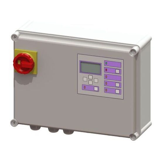
- Page 76 2.4 预期用途 Comfort Plus电控箱用于控制污水提升器或提升泵站。 可使用探头、浮球开关或压力传感器检测液位。 液位达到启动 液位时,提升泵功能将激活。 液位下降后,提升泵关闭功能将 自动运行。 ➲ 使用某些类型的泵时,可能需调整电机保护开关( “4.2 连接 污水提升泵”)。 电控箱本身不装在EX区。 未经制造商书面明确批准就改装系统或在系统中安装附加装置、 使用非原装备件以及安排未经制造商批准的公司或人士实施维修 均会导致保修失效。 2.5 产品描述 电控箱用于自动控制各种不同的泵站与污水提升器。 根据使用 的型号,连接230 V(安全插头)或400 V(终端)电源。 我们 提供拥有不同开断容量(A)的电控箱。 插图 [27] 功能部件 主开关 显示和控制面板 铭牌 电缆槽,连接 安装和操作手册 010-700_01...
- Page 77 2.5.1 有关ATEX设计的附加信息 技术规格(单一防爆栅) 液位电路 本安型Ex ia IIC 满足EN 50014 + A1-A2、EN II (1) GD [Ex ia Ga] IIC 50020:2002标准规定的要求。. 浮球开关端子: 关闭、开启1、开启2、报警 允许的空气湿度 10-80%,无冷凝 液位探头端子: 探头2 bk + bl 最大工作高度 海平面以上2000 m 最大值*: 单泵系统:11 VA / 双泵系 最大耗电量 统:15 VA 28 V 三相电流...
- Page 78 3. 技术数据 Comfort Plus 230 V Comfort Plus 400V 开关输出时的最大功率 (功率因数=1) 标测电流范围*A 4.0 - 6.3 A 6.3 - 10 A 2.5 - 4.0 A 4.0 - 6.3 A 6.3 - 10 A 重量 4.0 kg 3.8 kg 尺寸(LxWxD), mm 380x280x130 230 V;...
- Page 79 4. 安装 (230V) 请按照第2章规定的安全说明操作。 文件结尾提供了PCB的总连接图。 拧紧扭矩见“插图 [28] 电缆槽连接扭矩”。 19mm 4.1 安装电控箱 (230V) 主开关(第 页插图[1])位于关闭位置时,方可打开电控箱“ 插图 [27]”,见第 页 76。 19mm 15mm · 拧松壳盖上的螺钉,打开壳盖。 • 将外壳装在规定位置,固定四角。 · 考虑环境条件。 包装清单中包含开孔器。 将系统隔离! 确保电缆与电气部件在作业过程中与电源 断连。 1-2mm ≈ 1Nm 4mm ≈ 3Nm 插图 [28] 电缆槽连接扭矩 010-700_01 安装和操作手册...
- Page 80 ➲ 连接400 V电源电缆 ( “插图 [29]”) · 将连接电缆经外壳开口连至终端线夹与主开关。 · 按照接线图执行(电控箱壳盖内的)连接作业。 · 拧紧电缆螺栓连接,确保密封。 PE N T1 T2 T3 230 V电源电缆 · 电控箱已做好插入电源的准备 安装其他其余的控制单元(选配) 与带双泵头的设备Pumpfix/Ecolift XL联用时,按电控箱说 明书将端子连至 端子排“LIN-BUS”。 插图 [29] 400 V电源电缆连接概览 电源 连接电缆 导线类型 标签 连接名称 保护接地 黄色/绿色 中性线 蓝色 电源 5极...
- Page 81 4.2 连接污水提升泵 ATEX: 1 连接提升泵前,检查电控箱的电机保护 开关是否适用于提升泵的当前电耗(见铭牌)。 ▶ 将电机保护开关的开启电流调至提升泵的标称电流(见提升泵的 铭牌)。 ▶ 将连接电缆穿过外壳开口,按螺栓连接的相同方式连至 电源电缆。 ▶ 按接线图连接。 本系统中的提升泵可分别使用3线、6线或9线电缆。 3线电缆 用于230 V配置,该配置使用的提升泵可通过电控箱底面外部的Pho- enix接触插头连接。 . 因此, 本节不提供有关该配置的其它信息 使用9线电缆时, ➲ T1 T2 污水提升泵中各相位的连接加倍( “插图 [30]”。 TF1** TF2** 6(9*) 污水提升泵的PCB连接 1-3(1-6*)相 ATEX: T1 T3 4-5(7-8 )温度监测 TF1和TF2 PE(保护接地)...
- Page 82 4.3 连接液位探测器 本文件结尾概述了PCB连接。 压力传感器(可选) 拆下密封盖 使用压力传感器检测液位需按以下步骤连接压力传感器。 将压力传感器的空气管拧到压力管的螺纹接套上(1),用防松螺 母固定。 保持装好的空气管有一定坡度。 如果空气管长于10 m或有反向管路坡度,利用压缩机组去除气泡 (见KSESSEL附件)。 插图 [31] 安装和操作手册 010-700_01...
- Page 83 浮球开关 如果使用浮球开关检测液位,将密封插头拉出,插入M16电缆螺 栓连接,用埋头螺母将其固定。 然后将电缆从螺栓连接中穿 过,并将盖子固定。 单泵浮球开关(非ATEX型) 将浮球开关电缆的两端连至图示端子。 ALARM Alarm A = 提升泵关闭(关闭) B = 提升泵开启(开启) D = 报警 插图 [32] 010-700_01 安装和操作手册...
- Page 84 双泵浮球开关(非ATEX型) 连接“插图 [33]” . Alarm Alarm A = 提升泵关闭(关闭) C = 提升泵2开启(开启2) B = 提升泵1开启(开启1) D = 报警 插图 [33] 安装和操作手册 010-700_01...
- Page 85 连接液位传感器 液位传感器连接概览 电线颜色 PCB上的名称 端子颜色 单泵/双泵液位传感器(非ATEX型) 连接“插图 [34]” (-)黑色 蓝色 探头2 单泵系统与双泵系统中的液位传感器的连接方式相同。 (+)红色 黑色 注意: 延伸液位探头连接电缆时,请使用 KESSEL接线盒(产品编号: 28799)。 Mono/Duo sw/BK rt/RD 插图 [34] 010-700_01 安装和操作手册...
- Page 86 单泵/双泵ATEX液位传感器 液位传感器连接概览 将ATEX液位传感器电缆的两端连至“插图 [35]” 齐纳防爆栅上的 电线颜色 单泵系统与双泵系统中的液位传感器的连接方式相同。 名称 红色(+) 黑色(-) 注意: 延伸液位探头连接电缆时,请使用KESSEL 接线盒(产品编号: 28799)。 rt/RD sw/BK 插图 [35] 安装和操作手册 010-700_01...
- Page 87 4.4 电机阀片功能(光学探头) 与Pumpfix/Ecolift XL联用时,必须将电机阀片1的光学探头 连至电控箱底面的深灰色Phoenix接触插头。 如果存在电机阀片2,必须按照冗余电控箱随附的说明书将该 阀片连至冗余电控箱。 4.5 在外部连接USB(可选) 为使PCB上的USB活接头在外壳未打开的情况下可够到,可向 KESSEL订购USB外壳活接头以及用于将该活接头装在电控箱的 电缆与连接器(产品编号: 28785)。 4.6 KESSEL 远程控制调制解调器(可选) 按照KESSEL远程控制调制解调器随附的安装说明书安装KES- SEL远程控制调制解调器(产品编号: 28792)。 4.7 其它可能的连接 外部信号发生器-报警(可选) - Kessel附件(产品编号: 20162)(相关连接说明,见 ➲ “6.3 4“6.3 400 V系统的接线图” 无源干接点(可选) - 附件,有多种形式,如报警灯(产品编号: 97715) 010-700_01 安装和操作手册...
- Page 88 5. 初始操作;初始化 确定电源电压(400V电控箱) ▶ 将电源电缆连至网电源。 ▶ 将主开关 调到开启位置 ✓ 初始化过程自动开始 • 装置检查电气部件 • 测试备用电池的电压 • 菜单项目 |3.10. 语言|显示。 确定电源电压(230V电控箱) ▶ 将安全插头插入指定的活接头。 ▶ 将主开关 调到开启位置 ✓ 初始化过程自动开始 • 装置检查电气部件 • 测试备用电池的电压 • 菜单项目 |3.10. 语言|显示。 插图 [36] 开启/关闭 故障显示 按初始操作部分的描述操作。 将主开关(1)调到位置 I(开启/关闭)。系统成功通过测试后,显示屏显示|0 系统信...
- Page 89 5.1 实施初始化 在初始化过程中,预计会生成以下输入: • |语言| • |日期/时间| • |产品类型| • |系统配置| • |额定功率| • |S1 / S3运行| • |设备维护保养间隔| 语言 ▶ 按“确定” ▶ 用光标键选择语言,然后按“确定”。 ✓ |日期/时间|菜单显示 日期/时间 ▶ 设置日期和时间,设置的数字将闪烁,然后按“确定”进 行确认。 插图 [39] 位置编号 操作键 ✓ |产品类型|菜单显示。 向上鼓动 产品类型 ▶ 选择混合动力污水提升器、污水提升器或提升泵站, “确定”键...
- Page 90 系统配置 ▶ 选择产品配置。 可在相应制造商文件中查找产品配置。 选择的项目会影响可用的设置选项。 ✓ |S1/S3运行|菜单显示。 S1 / S3运行 ▶ 选择运行模式。 可在相应制造商文件中查找运行模式。 完成 最后一项输入后,|设备维护保养间隔|菜单显示。 设备维护保养间隔 ▶ 输入标准规定的设备维护保养间隔。 ✓ 初始化完成,电控箱可用。 5.2 功能检查 按照系统安装与维护说明书以及所有附加部件的安装与维护说明 书执行功能检查。 安装和操作手册 010-700_01...
- Page 91 设备维护保养 读出数据 6.1 更新与读出数据 选择 |读出数据| ,然后按“ 不得连接外部硬盘,否则电控箱 确定”。包含系统数据的文 无法工作(电源不大于100 mA)。 使用前,必须在Windows PC 连接USB闪存盘。 件(* .csv)存储在USB闪存盘 通过FAT将USB闪存盘格式化, 中。 并为USB闪存盘命名。 更新 USB闪存盘连接到电控箱后,USB闪存盘将被自动检测到。 然 后,显示屏将显示含以下选项的数据传输菜单: 连接USB闪存盘后,显示屏显示数据 选择|软件更新|, 输入密码, 传输菜单。 然后按“确定”,更新过程将 • |0.1 读出数据| (仅当USB闪存盘中有相应的文件 自行进行,仅需按显示屏显示 • |0.2 软件更新| (* .hex)时,方可实施该操作) 的对话操作。 • |0.3 读入参数 | 读入参数...
- Page 92 6.2 更换电池 Comfort PLUS电控箱装有电池,以备断电时使用。 如果显示屏 指示需更换电池,必须更换电池。 更换电池: 将系统隔离! 确保电缆与电气部件在作业过程中与电源 断连。 ▶ 将电控箱上的主开关(1)调到关闭位置,然后打开外壳。 ▶ 解开电缆绑带,取出电池(2),换上新电池。 ▶ 用电缆绑带固定电池。 插图 [37] 安装和操作手册 010-700_01...
- Page 93 6.3 400 V系统的接线图 Brücke Brücke Bridge Bridge 电桥 电桥 Optional: SIGNAL- SICHERUNG 选项: gn or or GEBER Fuse 保险 Signaling device 230VAC 50Hz 1 2 3 4 5 1 2 3 4 5 信号传感器 SCHWIMMER +24V floater PUMPE 2 PUMPE 1 浮标开关...
- Page 94 Brücke Brücke Bridge Bridge 电桥 电桥 Optional: SIGNAL- SICHERUNG 选项: gn or or GEBER Fuse 保险 Signaling device 信号传感器 230VAC 50Hz T1 T3 PE T1 T3 6 (9*) 6 (9*) SCHWIMMER +24V floater PUMPE 2 PUMPE 1 浮标开关 FERN- Pump 2 Pump 1 BEDIENUNG 泵...
- Page 95 6.4 400 V ATEX系统的接线图 Brücke Brücke rt/RD sw/BK Bridge Bridge 电桥 电桥 Optional: SIGNAL- SICHERUNG 选项 gn or or GEBER Fuse 保险 Signaling device 信号传感器 230VAC 50Hz T1 T2 PE T1 T2 SCHWIMMER 6 (9*) 6 (9*) +24V floater PUMPE 2 PUMPE 1 浮标开关...
- Page 96 6.5 230 V系统的接线图 T1 T2 2 4 6 NCA2 2 4 6 NCA2 Brücke Brücke Bridge Bridge 电桥 电桥 SIGNAL- Optional: SICHERUNG 选项: gn or PE N GEBER Fuse 保险 Signaling device 230VAC 50Hz 信号传感器 SCHWIMMER +24V floater 浮标开关 PUMPE 1 PUMPE 2 FERN- Pump 1...
- Page 97 7. 配置菜单概述 显示的参数与设置选项取决于在电控箱中设置的系统传感器 与产品配置(如:| Pumpfix / Ecolift XL,双泵 | 双电机阀 片 | SPF 3000 |)。 如果个别菜单项目不可用,检查电控箱 的配置与系统是否匹配。 如需检查,选择“信息”子菜单中的 | 1.3 控制类型|。 - bzw. Schwimmeranzeige 菜单的序号(3)显示在显示屏的顶部。 “5.1 实施初始 化”“5.1 实施初始化” 插图 [38] 菜单结构 系统信息 信息 工作时长 1.1.1 总运行时长 0 - 999,999.9 1.1.2 提升泵1运行时长...
- Page 98 1.1.9 倒灌次数 0 - 999,999 1.1.10 阀片开关次数 0 - 999,999 设备运行记录书 控制类型 设备维护保养到期日 1.4.1 上次设备维护保养日期 年.月.日 时:分. 1.4.2 下次设备维护保养日期 年.月.日 时:分. 当前 测量值 1.5.1 电源电流 0 - 99.9 1.5.2 电池电压 0 - 99.9 1.5.3 液位 mmWS 0 - 5000 1.5.4 电源电压...
- Page 99 1.6.11 开启1液位 0 - 5000 1.6.12 关闭1液位 0 - 5000 1.6.13 报警液位 0 - 5000 1.6.14 开启2液位 0 - 5000 1.6.15 关闭2液位 0 - 5000 1.6.16 阀片开启延时 0 - 99 1.6.17 阀片后运行时间 0 - 99 1.6.18 阀片最大电流 150 - 200 1.6.19 提升泵S1 / S3运行...
- Page 100 2.6.2 6个月 2.6.3 12个月 2.6.4 手动设备维护保养 2.6.5 无设备维护保养间隔 清空远程控制 2.7.1 清空持续时间 2.7.2 禁用 压力传感器校准 设置 参数 3.1.1 开启延时 0 - 99 3.1.2 运行时间 0 - 99 访问代码 1000 3.1.3 最大 电流 3.5 - 9.5 3.1.4 最小 电流 0.5 - 2.5 3.1.5 工作次数限值...
- Page 101 3.1.18 阀片最大电流 150 - 200 3.1.19 提升泵S1 / S3运行 S1运行 / S3运行 3.1.30 远程控制访问 配置文件记忆 3.2.1 保存参数 3.2.2 加载参数 日期/时间 年月日时分. 系统配置 产品类型 3.5.1 Pumpfix / Ecolift XL,单泵 3.5.2 Pumpfix / Ecolift XL,双泵 3.5.3 Aqualift单泵污水提升器 3.5.4 Aqualift双泵污水提升器 3.5.5 Aqualift单提升泵站 3.5.6 Aqualift双提升泵站...
- Page 102 3.6.14 F XL 200 l,双泵 3.6.15 F XL 300 l,双泵 3.6.16 F XL 450 l,双泵 3.6.17 S Underfloor,双泵 3.6.18 S,双泵 3.6.19 特殊双泵污水提升器 3.6.20 F XL,单泵 (ATEX) 3.6.21 S,单泵 3.6.22 -无- 3.6.23 F AP 501,单泵,LW 800 3.6.24 F AP 501,单泵,LW 1000 3.6.25 F,非ATEX型...
- Page 103 额定功率 3.7.1 KTP500 (230V) 3.7.2 KTP1000 (230V) 3.7.3 SPF 1400 (230V) 3.7.4 SPF 1500 (400V) 3.7.5 SPF 3000 (400V) 3.7.6 SPF 4500 (400V) 3.7.7 SPF 5500 (400V) 3.7.8 1,9 kW 3.7.9 1.3 kW 3.7.10 Ama Porter 3.7.50 特殊提升泵 3.7.11 230 V / 2.5 - 4 A 3.7.12 230 V / 4 - 6.3 A 3.7.13...
- Page 104 传感器配置 3.8.1 压力传感器+光学探头 3.8.2 压力传感器 3.8.3 压力传感器 + 浮球开关报警 3.8.4 压力传感器 + 鼓泡 3.8.5 液位传感器 3.8.6 液位传感器 + 浮球开关报警 3.8.7 浮球开关 3.8.8 无关闭液位的浮球开关 通信 3.9.1 站名 3.9.2 本机编号 3.9.3 调制调解器类型 3.9.4 3.9.5 文本信息-总部 3.9.6 文本信息-目的地1 3.9.7 文本信息-目的地2 3.9.8 文本信息-目的地3 3.9.9 状态...
- Page 105 3.12.2 电池监测 开启/关闭 3.12.3 自动报警确认 开启/关闭 3.12.4 TP常数 0 - 9999 3.12.5 电池阈值 0 - 18.0 3.12.6 旋转磁场 开启/关闭 3.12.7 交替运行 开启/关闭 3.12.8 重置计数器 3.12.9 交流输出 开启/关闭 3.12.10 直流输出 开启/关闭 3.12.11 文本信息-间隔 每周/每日/每 小时 3.12.12 OPT故障检测时间 0 - 30 3.12.13 OPT逻辑时间...
- Page 106 数据交换 读出数据 软件更新 读入参数 安装和操作手册 010-700_01...
Need help?
Do you have a question about the Comfort PLUS and is the answer not in the manual?
Questions and answers