Table of Contents
Advertisement
Available languages
Available languages
Quick Links
ANLEITUNG FÜR EINBAU, BEDIENUNG UND WARTUNG
KESSEL - Schaltgerät
Aqualift Comfort 230V Mono/Duo
Installation
der Anlage wurde durchgeführt von ihrem Fachbetrieb:
Name /Unterschrift
Stand 2018/06
Inbetriebnahme
Datum
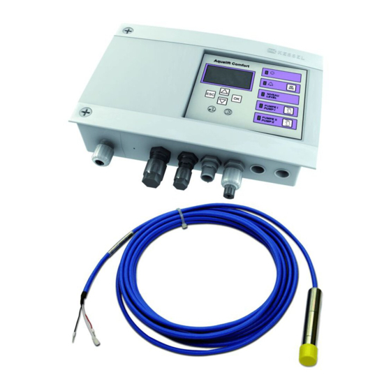
Abb. zeigt:
Schaltgerät
Aqualift Comfort
230V Mono
Abb. zeigt:
Schaltgerät
Aqualift Comfort
230V Duo
Einweisung
Stempel Fachbetrieb
Ort
Produktvorteile
Für Mono- und
Duoanlagen lieferbar
Anwenderfreundlich
Menüführung im
mehrzeiligen Display
Mit Selbstdiagnose-
system SDS und
Erinnerungsfunktion für
die nächste Wartung
Anzeige der aktuellen
Messwerte
Einfache Einstellung der
funktionsrelevanten
Parameter
Betriebsstundenzähler
mit USB-Platinenbuchse
für einfaches Auslesen
des Logbuches
Optionale Weiterleitung
von Alarm- und
Sammelstörmeldungen
über GSM-Schnittstelle
Sach-Nr. 010-910DE_EN
Seite 1
Page 35
Advertisement
Chapters
Table of Contents

Related Manuals for Kessel Aqualift Comfort 230V Duo


Summary of Contents for Kessel Aqualift Comfort 230V Duo
- Page 1 ANLEITUNG FÜR EINBAU, BEDIENUNG UND WARTUNG KESSEL - Schaltgerät Seite 1 Aqualift Comfort 230V Mono/Duo Page 35 Produktvorteile Für Mono- und Duoanlagen lieferbar Anwenderfreundlich Menüführung im mehrzeiligen Display Abb. zeigt: Mit Selbstdiagnose- Schaltgerät system SDS und Aqualift Comfort 230V Mono Erinnerungsfunktion für...
-
Page 2: Table Of Contents
Allgemeines Einleitung und Begrüßung Produktbeschreibung, allgemein 1.2.1 Ausführungen 1.2.2 Typenschild Lieferumfang Allgemeine Hinweise zu dieser Betriebs- und Wartungsanleitung Baugruppen und Funktionselemente 1.5.1 Display und Bedienfeld, Anzeigen Sicherheit Bestimmungsgemäße Verwendung Personalauswahl und -qualifikation Organisatorische Sicherheits-Maßnahmen Gefahren, die vom Produkt ausgehen Gefahr durch elektrischen Strom und Kabel Montage Schaltgerät montieren Abwasserpumpe(n) anschließen... - Page 3 Anhang Menüstruktur Schaltgerät umrüsten, spezielle Bedingungen 7.2.1 Anschlüsse auf Klemmleiste herstellen Alternative Sensorkonfiguration (Schwimmer und Sensoren anschließen) 7.3.1 Aqualift Comfort Mono 230V 7.3.2 Aqualift Comfort Duo 230V Sonstiges 7.4.1 Anschlusskabel Pumpe / Sensor kürzen oder verlängern 7.4.2 Update und Daten auslesen 7.4.3 USB Anschluss herausführen 7.4.4 Menüstruktur Expertenmodus 2018/06...
-
Page 4: Allgemeines
Sind zwei Abwasserpumpen angeschlossen, werden diese je nach Füllvolumen und Positionierung der Niveau- sensoren entweder einzeln oder gemeinsam eingeschaltet. 1.2.1 Ausführungen Das Schaltgerät Aqualift Comfort wird in diesen Ausführungen hergestellt: Aqualift Comfort 230V Mono Aqualift Comfort 230V Duo Anschluss für eine Abwasserpumpe Anschlüsse für zwei Abwasserpumpen 4/68 2018/06... -
Page 5: Typenschild
ALLGEMEINES 1.2.2 Typenschild Informationen auf den Typenschildern der Anlage Bezeichnung des Schaltgerätes Artikel-Nummer des Schaltgerätes Bahnhofstraße 31 Anschlussspannung und Anschlussfrequenz D-85101 Lenting Aqualift Comfort Leistung 230V Duo Schutzart (IP) 28746 P: max. 3,2 kW Seriennummer Ue: 230 VAC - 50 Hz Gefahrenzeichen (elektr. -
Page 6: Allgemeine Hinweise Zu Dieser Betriebs- Und Wartungsanleitung
ALLGEMEINES 1.4. Allgemeine Hinweise zu dieser Betriebs- und Wartungsanleitung Verwendete Symbole und Legenden <1> Hinweis im Text auf eine Legendennummer in einer Abbildung Bezug auf eine Abbildung • Arbeitsschritt Aufzählung Kursiv Kursive Schriftdarstellung: Bezug zu einem Abschnitt / Punkt im Steuerungs-Menü VORSICHT: Warnt vor einer Gefährdung von Personen und Material. -
Page 7: Display Und Bedienfeld, Anzeigen
ALLGEMEINES 1.5.1 Display und Bedienfeld, Anzeigen Pumpe 1 Pumpe 2 Alarm Betriebsbereit Aqualift Comfort Niveau/Level Pfeil oben Blättern im Niveau Pfeil unten Blättern im Menü Löschen einer Eingabe Alarm Quittierung des akustischen Signals Pumpe/Test Pumpe 1 EIN / AUS Bestätigen einer Eingabe, nächste Ebene Pumpe /Test Pumpe 2 EIN / AUS * Version Schaltgerät Aqualift Comfort Duo 2018/06... -
Page 8: Sicherheit
SICHERHEIT Sicherheit 2.1. Bestimmungsgemäße Verwendung Das Schaltgerät Aqualift ist ausschließlich für die Steuerung von Hebeanlagen (DIN EN 12050 Teil 1-3) und Pump- stationen für fäkalienfreies und fäkalienhaltiges* Abwasser zu verwenden. Ein Einsatz des Schaltgeräts in explosionsgefährdeter Umgebung ist unzulässig. Je nach Ausführung (siehe 1.2.1) ist der Anschluss von Schwimmerschaltern vorgesehen Alle nicht durch eine ausdrückliche und schriftliche Freigabe des Herstellers erfolgten - Um- oder Anbauten - Verwendungen von nicht originalen Ersatzteilen... -
Page 9: Montage
MONTAGE Montage 3.1. Schaltgerät montieren Achtung, Gefahr durch elektrischen Strom! Das Schaltgerät darf nur geöffnet werden, wenn der Netzanschluss getrennt ist. • Netzanschluss trennen, und das Gehäuse öffnen, dazu die beiden Schrauben <29> lösen (Linksdrehung) und den Gehäusedeckel aufklappen. • Gehäuse am vorgesehenen Ort montieren, dazu beide Befestigungsmöglichkeiten verwenden. -
Page 10: Abwasserpumpe(N) Anschließen
MONTAGE 3.2. Abwasserpumpe(n) anschließen Achtung, Gefahr durch elektrischen Strom bei unbefugtem Öffnen eines Steckers während dem Betrieb durch z.B. Kinder! Die Befestigungsmutter des Steckers muss so fest angezogen werden, dass Kinder sie nicht öffnen können. Abwasserpumpe(n) anschließen, dazu für jede Pumpe •... -
Page 11: Niveaugeber Anschließen
MONTAGE 3.3. Niveaugeber anschließen 3.3.1 Drucksensor Drucksensor zur Ermittlung der Pegelstände, an denen die Pumpe(n) ein- / ausgeschaltet werden, anschließen. Zur Vermeidung von Kondenswasserbildung im Inneren der Druckleitung, muss diese stetig ansteigend verlegt werden. • Druckleitung vom Tauchrohr auf den Anschlussnippel des Druckleitungsanschlusses <17>... -
Page 12: Erstinbetriebnahme
MONTAGE 3.4. Erstinbetriebnahme Ein Trockenlauf der Pumpe(n) ist unbedingt zu vermeiden. Tipp: Befüllen Sie den Abwasserbehälter vor dem Herstellen der Netzspannung so weit mit Wasser, dass im Fall eines unbeabsichtigten Einschaltens der Pumpe(n) (z.B. fehlerhafter Anschluss eines Niveausensors) diese nicht trocken laufen können. •... -
Page 13: Funktionskontrolle
MONTAGE Typ Aqualift Sind die Pumpen der Anlage auf das Schaltgerät abgestimmt (Original KESSEL-Produkte), Einstellung wie bei A) beschrieben vornehmen, wenn nicht, weiter bei B). • OK betätigen • A) Art der angeschlossene(n) Pumpe(n) mit den Pfeiltasten auswählen und mit OK bestätigen, das Menü 0 Sys- teminfo wird angezeigt - das Schaltgerät ist betriebsbereit. -
Page 14: Einstellungen, Menü
MONTAGE • Abwasserbehälter bis zur Markierung befüllen. • Handbetrieb nicht weiterführen, dazu Taste <71> (<73>) nicht erneut betätigen, das Schaltgerät schaltet an- schließend die Pumpe(n) ein, der Abwasserbehälter wird entleert*. * bei der Ausführung Duo darauf achten, dass das Ausschalten der zweiten Pumpe entsprechend zum Pegel- stand des Abwassers funktioniert. - Page 15 ALLGEMEINES • OK <72> betätigen, Ebene 1 des Menüs (siehe 7.1, Menüstruktur) wird aktiviert. Notiz: Je nach Konfiguration kann die Displayanzeige abweichen Datum --,--,-- Uhrzeit --,--,-- Niveau: -- mm Pumpe I: Pumpe II: Fehler/Meldung/Ereignis (Statuszeile) [13] Navigation innerhalb des Menüs Aktion Bedienung Menüpunkt auswählen...
-
Page 16: Betrieb
BETRIEB Betrieb 4.1. Einschalten • Netzanschluss herstellen, nach erfolgreichem Systemtest erscheint im Display <23> das Menü 0 Systeminfo und die grüne LED <22> leuchtet, das Schaltgerät Aqualift Comfort ist betriebsbereit. Aqualift Comfort 4.2. Alarm quittieren Alarmmeldung im Normalbetrieb Ist ein Zustand aufgetreten, der eine Alarmeldung auslöste (z.B. -
Page 17: Technische Daten
TECHNISCHE DATEN Technische Daten Schaltgerät Aqualift Comfort Mono Gehäuseabmessungen (LxBxT) 210x200x75 295x200x75 Gewicht Schaltgerät ca. 1,2 kg ca. 1,4 kg Betriebsspannung 230 V AC 50 Hz Nennstrom (in Betrieb) je nach Pumpe Strombereich 1 - 10 A 2 x 1 - 10 A max. -
Page 18: Wartung
WARTUNG Wartung 6.1. Wartungstermin einstellen Der Wartungstermin wird über das Menü 2, Punkt 2.4 eingestellt (Siehe 7.1). Folgen Sie dem Bildschirmdialog (zur Bedienung siehe 3.5, Einstellungen, Menü). 6.2. Selbstdiagnosesystem (SDS) Das Selbstdiagnosesystem prüft automatisch (Intervall einstellbar) nachstehend beschriebene Anlagenfunktio- nen. Diese Einstellungen werden über das Menü 3.1.9 (Siehe 7.1) vorgenommen. Prüfung: Pumpe 1, Pumpe 2 (Duo), Batterie Tritt ein Fehler auf, erscheint eine Klartextmeldung im Display und die Alarm-LED leuchtet. -
Page 19: Fehlersuche
WARTUNG 6.4. Fehlersuche Anzeigetext Mögliche Ursache Abhilfemaßnahme Batteriefehler Batterie fehlt, ist defekt oder Rest- Batterieanschluss prüfen, ggf. Batterie erset- spannung zu klein zen. Wartungstermin (blinkt) - Wartungstermin ist erreicht - Wartung durchführen - Kein Wartungstermin eingegeben - Wartungstermin eingeben (siehe 6.1) Unterstrom 1 - minimale Stromaufnahme der Kabel prüfen ggf. -
Page 20: Anhang
ANHANG Anhang 7.1. Menüstruktur Die Nummer <24> der jeweiligen Menüebene wird in Ziffernform in der obersten Displayzeile dargestellt. Datum --,--,-- Uhrzeit --,--,-- Niveau: -- mm Pumpe I: Pumpe II: Fehler/Meldung/Ereignis (Statuszeile) [16] 0 Systeminfo 1 Information 1.1 Betriebsstunden 1.1.1 Gesamtlaufzeit Taste OK betätigen, um in die Ebenen 1 bis 3 zu gelangen 1.1.2 Laufzeit Pumpe 1... - Page 21 ANHANG 2 Wartung 2.1 Handbetrieb 2.1.1 Pumpe 1 2.1.2 Potentialfreier Kontakt 2.1.3 Externer Signalgeber 2.1.4 Kommunikation 2.1.5 Pumpe 2* 2.2 Automatikbetrieb* 2.3 SDS Selbstdiagnosesystem 2.3.1 SDS Selbstdiagnosesystem* 2.4 Wartungstermin 2.4.1 Letzte Wartung 2.4.2 Nächste Wartung 2.5 Wartung durchgeführt 2.6 Wartungsintervall 2.6.1 Gewerblich 3 Monate 2.6.2...
- Page 22 3.6.3 Modemtyp 3.6.4 3.6.5 SMS-Zentrale 3.6.6 SMS-Ziel 1 3.6.7 SMS-Ziel 2 3.6.8 SMS-Ziel 3 3.6.9 Status 3.7 Sprache 3.7.1 Deutsch 3.7.2 English 3.7.3 Francais 3.7.4 Italiano 3.7.5 Nederlands 3.7.6 Polski 3.8 Rücksetzen * Ausführung Aqualift Comfort 230V Duo 22/68 2018/06...
-
Page 23: Schaltgerät Umrüsten, Spezielle Bedingungen
-qualifikation). 7.2.1 Anschlüsse auf Klemmleiste herstellen Sollen Sonden oder Pumpen angeschlossen werden, die nicht vom Hersteller KESSEL mit einer passenden elek- trischen Steckverbindung ausgerüstet sind, können - entsprechende Steckverbindungen beim Hersteller KESSEL bestellt werden. - die Anschlüsse im Gehäuseinneren an den Klemmleisten hergestellt werden. Dazu wie folgt verfahren: •... -
Page 24: Alternative Sensorkonfiguration (Schwimmer Und Sensoren Anschließen)
ANHANG 7.3. Alternative Sensorkonfiguration (Schwimmer und Sensoren anschließen) Die nachstehenden Anschlussbeschreibungen beziehen sich auf die im Menü 3.5 auswählbaren Sensorkonfigurationen. 7.3.1 Aqualift Comfort Mono 230V Menüpunkt 3.5.1, Drucksensor und Optische-Sonde Diese Sensorkonfiguration ist folgenden im Menü auswählbaren Anlagenkonfigurationen (Typ Aqualift) zugeord- net: 3.4.1 und 3.4.6 bis 3.4.12. - Page 25 ANHANG Menüpunkt 3.5.3, Drucksensor <34> und Alarmschwimmer <36> Anschluss des Drucksensors siehe Kapitel 3.3.1. cable br bl MODEM ALARM (/(&752'( fash drive [19] Menüpunkt 3.5.4, Drucksensor und Lufteinperlung Anschluss des Drucksensors siehe Kapitel 3.3.1. Die Lufteinperlung entsprechend der Installationsanleitung installieren. Menüpunkt 3.5.5, Drucksensor und Lufteinperlung und Alarmschwimmer Anschlusschema wie bei 3.5.3.
- Page 26 ANHANG Menüpunkt 3.5.8, Schwimmer ohne AUS-Nivau Alarm <38> Pumpe EIN <39> cable br bl MODEM ALARM (/(&752'( fash drive [21] Menüpunkt 3.5.9 Pegelsonde • Werkseitige Verdrahtung der Steckerbuchse, an der der Alarmsensor angeschlossen werden kann (Kapitel 3.3.2) entfernen. • Pegelsonde <42> wie folgt anschließen: 1 = Aderfarbe schwarz 3 = Aderfarbe rot cable br bl MODEM...
- Page 27 ANHANG Menüpunkt 3.5.11, Leitfähigkeit-Sonde cable cable br bl br bl MODEM MODEM ALARM ALARM (/(&752'( (/(&752'( fash drive fash drive [23] EIN-Niveau festgelegt Anschluss* Artikelnummer 1 <37> 127-033 * entspricht Kabelbeschriftung EIN-Niveau variabel Anschluss* Artikelnummer 1 <43> 127-029 <44> 127-030 * entspricht Kabelbeschriftung Menüpunkt 3.5.12, Drucksensor Anschluss des Drucksensor siehe Kapitel 3.3.1.
-
Page 28: Aqualift Comfort Duo 230V
ANHANG 7.3.2 Aqualift Comfort Duo 230V Menüpunkt 3.5.1, Drucksensor und Optische-Sonde Diese Sensorkonfiguration ist folgenden im Menü auswählbaren Anlagenkonfigurationen (Typ Aqualift) zugeord- net: 3.4.1 und 3.4.6 bis 3.4.12. Anschlüsse der Sensoren siehe Kapitel 3.3.1 und 3.3.2. Menüpunkt 3.5.2, Drucksensor <34> und Leitfähigkeit-Sonde <37> cable br bl MODEM... - Page 29 ANHANG Menüpunkt 3.5.3, Drucksensor <34> und Alarmschwimmer <36> Anschluss des Drucksensors siehe Kapitel 3.3.1. cable br bl MODEM ALARM (/(&752'( fash drive [25] Menüpunkt 3.5.4, Drucksensor und Lufteinperlung Anschluss des Drucksensors siehe Kapitel 3.3.1. Die Lufteinperlung entsprechend der Installationsanleitung installieren. Menüpunkt 3.5.5, Drucksensor und Lufteinperlung und Alarmschwimmer Anschlusschema wie bei 3.5.3.
- Page 30 ANHANG Menüpunkt 3.5.8, Schwimmer ohne AUS-Nivau Alarm <38> Pumpe 1 EIN <39> Pumpe 2 EIN <40> cable br bl MODEM ALARM (/(&752'( fash drive [27] Menüpunkt 3.5.9 Pegelsonde • Werkseitige Verdrahtung der Steckerbuchse, an der der Alarmsensor angeschlossen werden kann (Kapitel 3.3.2) entfernen.
- Page 31 ANHANG Menüpunkt 3.5.11, Leitfähigkeit-Sonde cable cable br bl br bl MODEM ALARM MODEM (/(&752'( (/(&752'( ALARM fash drive fash drive [29] Anschluss entspricht Kabelbeschriftung Variante 1 Artikelnummer <45> 127-047 <46> 127-034 Variante 2 <48> 127-037 <47> 127-036 Menüpunkt 3.5.12, Drucksensor Anschluss des Drucksensor siehe Kapitel 3.3.1.
-
Page 32: Sonstiges
ANHANG 7.4. Sonstiges 7.4.1 Anschlusskabel Pumpe / Sensor kürzen oder verlängern Bestellbare Verlängerungen (Länge 10m) Art.-Nr. 80889 Sonde, Art.-Nr. 80890 Motor Art. Nr. 80891 Pumpe Die maximale Leitungslänge von 30 m darf nicht überschritten werden. Wird ein Anschlusskabel gekürzt, muss das Auflegen der Adern gemäß... -
Page 33: Usb Anschluss Herausführen
7.4.3 USB Anschluss herausführen Damit der auf der Platine befindliche USB-Anschluss ohne ein Öffnen des Gehäuses zugängig wird, kann eine USB-Gehäusebuchse mit Kabel und Stecker zum Einbau in das Gehäuse des Schaltgerätes bei KESSEL bestellt werden (Siehe 5.1). 7.4.4 Menüstruktur Expertenmodus Experten-Modus 3.9.1... - Page 34 Führend in Entwässerung Privater Wohnungsbau ohne Kanalanbindung 1 2 3 4 1 2 3 4 Öffentlicher Bau z.B. Krankenhaus Öffentlicher Bau z.B. Freizeitanlagen 1 2 3 4 Gewerblicher Bau z.B. Hotel Gewerblicher Bau z.B. Industriebau 2 3 5 Gewerblicher Bau z.B.
- Page 35 MANUAL FOR INSTALLATION, OPERATION AND MAINTENANCE KESSEL - Control Unit Aqualift Comfort 230V Mono/Duo Product advantages Available for Mono and Duo stations User-friendly Menu navigation with multi-line display Figure shows: With SDS self-diagno- Aqualift sis system and reminder Mono Comfort...
- Page 36 General Introduction and welcome Product description, general 1.2.1 Versions 1.2.2 Type plate Delivery scope General information about this operating and maintenance manual Assemblies and functional elements 1.5.1 Display and control panel, displays Safety Proper use Staff selection and qualification Organisational safety measures Risks arising from the product Risk due to electrical current and cables Assembly...
- Page 37 Appendix Menu structure Control unit retrofits, special conditions 7.2.1 Terminal strip connections Alternative sensor configuration (connecting floaters and sensors) 7.3.1 Aqualift Comfort Mono 230V 7.3.2 Aqualift Comfort Duo 230V Miscellaneous 7.4.1 Shortening or extending the pump/sensor connection cable 7.4.2 Updates and data read 7.4.3 Leading out the USB connection 7.4.4 Menüstruktur Expertenmodus 2018/06...
-
Page 38: General
1.2.1 Versions The Aqualift Comfort control unit is produced in the following versions: Aqualift Comfort 230V Mono Connection for one wastewater pump Aqualift Comfort 230V Duo Connections for two wastewater pumps 38/68 2018/06... -
Page 39: Type Plate
GENERAL 1.2.2 Type plate Information on the type plate Designation of the control unit Item number of the control unit Bahnhofstraße 31 Connection voltage and connection frequency D-85101 Lenting Aqualift Comfort Power 230V Duo Protection degree (IP) 28746 P: max. 3,2 kW Serial number Ue: 230 VAC - 50 Hz Risk symbols (electr. -
Page 40: General Information About This Operating And Maintenance Manual
GENERAL 1.4. General information about this operating and maintenance manual Used symbols and legends <1> Reference in the text to a legend number in an illustration Reference to an illustration • Work step List Italics Text in italics: reference to a paragraph/item in the control menu CAUTION: Warns about a risk to persons and material. -
Page 41: Display And Control Panel, Displays
GENERAL 1.5.1 Display and control panel, displays Pump 1 Pump 2 Alarm Ready for operation Aqualift Comfort 65* LED Level Up arrow Scroll in the menu Down arrow Scroll in the menu Delete an entry, back Alarm Acknowledge the acoustic alarm Pump/Test Pump 1 ON/OFF Confirm an entry, next level 73* Pump /Test Pump 2 ON/OFF... -
Page 42: Safety Proper Use
SAFETY Safety 2.1. Proper use The Aqualift control unit may be used exclusively for controlling lifting stations (DIN EN 12050 Parts 1–3) and pumping stations for wastewater with sewage* and without sewage. Any use of the control unit in an environment at risk from explosions is not permissible. Depending on the version (see 1.2.1), it is possible to connect float switches. -
Page 43: Assembly
ASSEMBLY Assembly 3.1. Assembling the control unit Caution: risk due to electrical current! The control unit must be disconnected from the mains before opening. • Disconnect the mains. Open the housing by undoing the two screws <29> (anticlockwise) and lifting up the housing cover. •... -
Page 44: Connecting The Wastewater Pump(S)
ASSEMBLY 3.2. Connecting the wastewater pump(s) Caution: risk due to electrical current if a plug is opened without authorisation during operation, e.g. by a child! The fastening nut for the plug must be tightened such that a child cannot open it.. Connect the wastewater pump(s) as follows: •... -
Page 45: Connecting The Level Detector
ASSEMBLY 3.3. Connecting the level detector 3.3.1 Pressure sensor Connect the pressure sensor for determining the filling levels for activation and deactivation of the pump(s). These must always be routed upwards to avoid the formation of condensation inside the pressure pipe.. •... -
Page 46: Initial Start-Up
ASSEMBLY 3.4. Initial start-up A dry run of the pump(s) must be avoided without fail. Tip: Before connecting the mains voltage, fill the waste- water container with water so that the pump(s) cannot run dry if they should be switched on accidentally (e.g. incorrect connection of a level sensor). -
Page 47: Function Check
ASSEMBLY Type Aqualift If the system pumps are tailored to the control unit (original KESSEL products), configure as per A). Otherwise, proceed as per B). • Press OK • A) Select the type of the connected pump(s) with the arrow keys and confirm with OK; the 0 System info menu is displayed –... -
Page 48: Settings, Menu
ASSEMBLY • Fill the wastewater container up to the marking. • Do not continue with manual operation; for this purpose, ensure that the <71> (<73>) key is not pressed again, the control unit will then switch the pump(s) on again and the wastewater container will be drained*. * In the Duo version, please ensure that the switching off of the second pump works properly according to the level of the wastewater. - Page 49 GENERAL • Actuate OK <72>; level 1 of the menu (see 7.1, Menu structure) is activated. Note: The display may vary depending on the configuration. Datum --,--,-- Uhrzeit --,--,-- Niveau: -- mm Pumpe I: Pumpe II: Fehler/Meldung/Ereignis (Statuszeile) [13] Navigation within the menu Action Operation Select menu item...
-
Page 50: Operating Mode
OPERATING MODE Operating mode 4.1. Switching on • Connect to the mains. After a successful system test, display <23> shows the 0 System info menu and the green LED <22> lights up; the Aqualift Comfort control unit is now ready for operation. Aqualift Comfort 4.2. -
Page 51: Technical Data
TECHNICAL DATA Technical data Aqualift Comfort control unit Mono Housing dimensions (LxWxD) 210x200x75 295x200x75 Weight of control unit approx. 1,2 kg approx. 1,4 kg Operating voltage 230 V AC 50 Hz Rated current (in operating mode) Depends on pump Current range 1 - 10 A 2 x 1 - 10 A Max. -
Page 52: Maintenance
MAINTENANCE Maintenance 6.1. Setting the maintenance date The maintenance date is set using menu 2, Item 2.4 (see 7.1). Follow the dialogue on the screen (for operation, see 3.5, Settings, menu). 6.2. Self diagnosis system (SDS) The self diagnosis system performs an automatic check (at a configurable interval) of the system functions descri- bed below. -
Page 53: Troubleshooting
MAINTENANCE 6.4. Troubleshooting Display text Possible cause Remedial action Battery error Battery is missing, is faulty or volta- Check battery connection and replace battery, ge is less if necessary Maintenance date - Maintenance date has been rea- - Carry out maintenance (flashing ched - Enter maintenance date (see 6.1) -
Page 54: Appendix Menu Structure
APPENDIX Appendix 7.1. Menu structure The number <24> of the respective menu level is displayed in numerical form in the top line of the display Datum --,--,-- Uhrzeit --,--,-- Niveau: -- mm Pumpe I: Pumpe II: Fehler/Meldung/Ereignis (Statuszeile) [16] 0 Systeminfo 1 Information 1.1 Hours of operation 1.1.1 Total running time... - Page 55 APPENDIX 2 Maintenance 2.1 Manual operation 2.1.1 Pump 1 2.1.2 Potentialfreier Kontakt 2.1.2 potential free contact 2.1.3 Audible alarm 2.1.4 Communication 2.1.5 Pump 2* Automatic operation SDS Self diagnosis system 2.3.1 SDS Self diagnosis system* Maintenance date 2.4.1 Last maintenance 2.4.2 Next maintenance Maintenance done...
- Page 56 Own number 3.6.3 Modem type 3.6.4 3.6.5 SMS-Center 3.6.6 SMS-Destination1 3.6.7 SMS-Destination2 3.6.8 SMS-Destination3 3.6.9 Status 3.7 Language 3.7.1 Deutsch 3.7.2 English 3.7.3 Français 3.7.4 Italiano 3.7.5 Nederlands 3.7.6 Polski 3.8 Reset * Aqualift Comfort 230V Duo version 56/68 2018/06...
-
Page 57: Control Unit Retrofits, Special Conditions
If you wish to connect sensors or pumps that have not been equipped with a suitable electrical plug connection by KESSEL, you can: - Order corresponding plug connections from KESSEL. - Make the connections inside the housing on the terminal strips. To do this: •... -
Page 58: Alternative Sensor Configuration (Connecting Floaters And Sensors)
APPENDIX 7.3. Alternative sensor configuration (connecting floaters and sensors) The following connection descriptions relate to the sensor configurations available from menu 3.5. 7.3.1 Aqualift Comfort Mono 230V Menu item 3.5.1, Pressure switch + Optical probe This sensor configuration is assigned to the following system configurations available from the menu (Type Aqualift): 3.4.1 and 3.4.6 to 3.4.12. - Page 59 APPENDIX Menu item 3.5.3, Pressure sensor <34> + Float switch alarm <36> For information on connecting the pressure sensor, see Section 3.3.1. cable br bl MODEM ALARM (/(&752'( fash drive [19] Menu item 3.5.4, Pressure sensor + Air compressor For information on connecting the pressure sensor, see Section 3.3.1. Install the air compressor in accordance with the installation instructions.
- Page 60 APPENDIX Menu item 3.5.8, Float switch without off level Alarm <38> Pump on <39> cable br bl MODEM ALARM (/(&752'( fash drive [21] Menu item 3.5.9 Level sensor • Remove the factory-fitted wiring of the plug socket to which the alarm sensor can be connected (Section 3.3.2). •...
- Page 61 APPENDIX Menu item 3.5.11, Probe conductivity cable cable br bl br bl MODEM MODEM (/(&752'( (/(&752'( ALARM ALARM fash drive fash drive [23] EIN-Niveau festgelegt Connection* Item number 127-033 * Corresponds to cable labelling ON - level fixed Connection* Item number <43>...
-
Page 62: Aqualift Comfort Duo 230V
APPENDIX 7.3.2 Aqualift Comfort Duo 230V Menu item 3.5.1, Pressure sensor + Optical probe This sensor configuration is assigned to the following system configurations available from the menu (Type Aqualift): 3.4.1 and 3.4.6 to 3.4.12. For sensor connections, see Section 3.3.1 and 3.3.2. Menu item 3.5.2, Pressure sensor <34>... - Page 63 APPENDIX Menu item 3.5.3, Pressure sensor <34> + Float switch alarm <36> For information on connecting the pressure sensor, see Section 3.3.1. cable br bl MODEM ALARM (/(&752'( fash drive [25] Menu item 3.5.4, Pressure sensor + Air compressor For information on connecting the pressure sensor, see Section 3.3.1. Install the air compressor in accordance with the installation instructions.
- Page 64 APPENDIX Menu item 3.5.8, Float switch without off level Alarm <38> Pump 1 on <39> Pump 2 on <40> cable br bl MODEM ALARM (/(&752'( fash drive [27] Menu item 3.5.9 Level sensor • Remove the factory-fitted wiring of the plug socket to which the alarm sensor can be connected (Section 3.3.2). •...
- Page 65 APPENDIX Menu item 3.5.11, Probe conductivity cable cable br bl br bl MODEM ALARM MODEM (/(&752'( (/(&752'( ALARM fash drive fash drive [29] Connection corresponding to cable labelling Variant 1 Item number <45> 127-047 <46> 127-034 Variant 2 <48> 127-037 <47>...
-
Page 66: Miscellaneous
APPENDIX 7.4. Miscellaneous 7.4.1 Shortening or extending the pump/sensor connection cable Available extensions (10 m long) - Item no. 80889 sensor - Item no. 80890 motor - Item no. 80891 pump The maximum cable length of 30 m must not be exceeded If a connection cable is shortened, connect the wires as per Fig. -
Page 67: Leading Out The Usb Connection
Leading out the USB connection To enable access to the USB connection on the circuit board without opening the housing, a USB housing port with cable and plug can be ordered from KESSEL for installation in the control unit housing (see 5.1).. 7.4.4 Menüstruktur Expertenmodus... - Page 68 Leading in Drainage Private homes without public sewage connection 1 2 3 4 1 2 3 4 Public buildings (e.g. hospital) Public buildings (e.g. leisure facility) 1 2 3 4 Commercial buildings (e.g. hotel) Commercial buildings (e.g. industrial / manu- facturing facilities) 2 3 5 Commercial buildings...
Need help?
Do you have a question about the Aqualift Comfort 230V Duo and is the answer not in the manual?
Questions and answers