Kessel Comfort PLUS Installation And Operating Instructions Manual
Hide thumbs
Also See for Comfort PLUS:
- Original operation manual (108 pages) ,
- Instructions for installation and operation manual (40 pages) ,
- Installation and operating manual (220 pages)
Table of Contents
Advertisement
Available languages
Available languages
Quick Links
Einbau- und Betriebsanleitung
DE
Einbau- und Betriebsanleitung....................................................................... 2
EN
Installation and operating instructions.......................................................... 24
FR
Instructions de pose et d'utilisation.............................................................. 46
IT
Istruzioni per l'installazione e l'uso...............................................................69
NL
Inbouw- en montagehandleiding.................................................................. 93
PL
Instrukcja zabudowy i obsługi.....................................................................116
2021/01
Schaltgerät
Comfort PLUS
010-700_04
Advertisement
Chapters
Table of Contents

Related Manuals for Kessel Comfort PLUS


Summary of Contents for Kessel Comfort PLUS
- Page 1 Schaltgerät Comfort PLUS Einbau- und Betriebsanleitung Einbau- und Betriebsanleitung............... 2 Installation and operating instructions............24 Instructions de pose et d’utilisation.............. 46 Istruzioni per l’installazione e l’uso...............69 Inbouw- en montagehandleiding..............93 Instrukcja zabudowy i obsługi..............116 2021/01 010-700_04...
-
Page 2: Table Of Contents
Liebe Kundin, lieber Kunde, als Premiumhersteller von innovativen Produkten für die Entwässerungstechnik bietet KESSEL ganzheitliche Systemlösun- gen und kundenorientierten Service. Dabei stellen wir höchste Qualitätsstandards und setzen konsequent auf Nachhaltig- keit - nicht nur bei der Herstellung unserer Produkte, sondern auch im Hinblick auf deren langfristigen Betrieb setzen wir uns dafür ein, dass Sie und Ihr Eigentum dauerhaft geschützt sind. -
Page 3: Hinweise Zu Dieser Anleitung
Hinweise zu dieser Anleitung Folgende Darstellungskonventionen erleichtern die Orientierung: Darstellung Erläuterung siehe Abbildung 1 Positionsnummer 5 von nebenstehender Abbildung Handlungsschritt in Abbildung Prüfen, ob Handbetrieb aktiviert wurde. Handlungsvoraussetzung OK betätigen. Handlungsschritt Anlage ist betriebsbereit. Handlungsergebnis Querverweis auf Kapitel 2 siehe "Sicherheit", Seite 4 Fettdruck besonders wichtige oder sicherheitsrelevante Information Variante oder Zusatzinformation (z. -
Page 4: Sicherheit
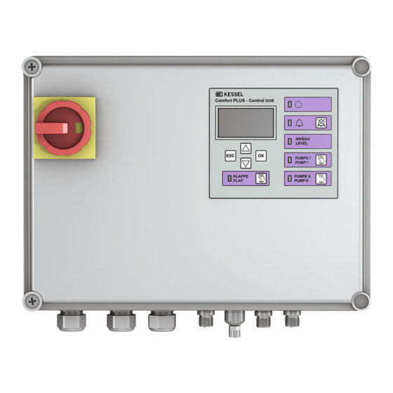
Der Betreiber der Anlage ist dazu verpflichtet: eine Gefährdungsbeurteilung zu erstellen, entsprechende Gefährdungszonen zu ermitteln und auszuweisen, Sicherheitsunterweisungen durchzuführen, gegen die Benutzung durch Unbefugte zu sichern. Person freigegebene Tätigkeiten an KESSEL-Anlagen Betreiber Sichtprüfung, Inspektion Sachkundiger (kennt, ver- Funktionskontrolle, Konfi- steht Betriebsanweisung) guration des Schaltgerätes... - Page 5 Reparaturen durchgeführt von nicht vom Hersteller autorisierten Betrieben oder Personen können zum Verlust der Gewährleistung führen. Produktbeschreibung PosNr. Funktionskomponenten Hauptschalter Display und Bedienfeld Typenschild Kabeldurchführungen, Anschlüsse PosNr. Display und Bedienfeld Comfort PLUS LED Alarm LED Niveauüberschreitung Handbetrieb Pumpe 1/2 Motorisierte Klappe auf-/zufahren Display mit Fehlermeldungsanzeige 010-700_04 5 / 144...
-
Page 6: Technische Daten
Technische Daten Angabe Comfort PLUS 230V Comfort PLUS 400V Maximale Leistung (kW) am Schaltausgang (bei cos φ = 1) Nennstrombereich 4,0 - 6,3 A 6,3 - 10 A 2,5 - 4,0 A 4,0 - 6,3 A 6,3 - 10 A... -
Page 7: Montage
Montage Sicherheitshinweise beachten, siehe "Sicherheit", Seite 4. Für eine Übersicht der Platinenanschlüsse, siehe "Anschluss- pläne", Seite 12 . Schaltgerät montieren WARNUNG Anlage freischalten! Sicherstellen, dass Leitungen und elektrische Komponenten während der Arbeiten von der Spannungsversorgung getrennt sind. Das Schaltgerät kann nur geöffnet werden, wenn sich der Hauptschalter in Position OFF befindet. Schrauben am Gehäusedeckel lösen und Gehäusedeckel aufklappen. - Page 8 Platinenanschlüsse für die Abwasserpumpe(n) (ATEX) Grün-gelbes Erdungskabel von Pumpe zu Schaltgerät führen und via separater Kabelverschraubung (beilie- gend) in das Schaltgerät hineinführen. Motorschutzschalter auf den Nennstrom der Pumpe ein- stellen (siehe Typenschild der Pumpe). U1, V1, W1 (U2, V2, W2 ): Phasen PE: Schutzleiter TF2: Temperaturüberwachung...
- Page 9 Abwasserpumpe(n) anschließen Vor Anschließen der Pumpe prüfen, ob der Motorschutz- ATEX: schalter des Schaltgerätes für die Stromaufnahme der Pumpe(n) (siehe Typenschild) geeignet ist. Ggf. Motorschutzschalter auf den Nennstrom der Pumpe einstellen (siehe Typenschild der Pumpe). Anschlusskabel durch die Gehäusedurchführunge(n) zie- hen und analog zur Kabelverschraubung der Netzleitung anziehen.
- Page 10 Drucksensor Soll ein Drucksensor zur Ermittlung des Füllstandes verwen- det werden, diesen wie folgt anschließen. Druckschlauch unter Zuhilfenahme einer Einzugsspi- rale durch das Kabelleerrohr hindurchführen, dazu das Schlauchende mit Verschlusskappe an der Einzugsspi- rale befestigen. Druckschlauchende mit Verschlusskappe passgenau abschneiden. Blauen Entriegelungsring einschieben und gedrückt hal- ten.
- Page 11 USB-Anschluss herausführen Damit der USB-Anschluss auf der Platine ohne ein Öffnen des Gehäuses zugänglich wird, kann eine USB-Gehäusebuchse mit Kabel und Stecker zum Einbau in das Gehäuse des Schaltgeräts bei KESSEL bestellt werden (Art.-Nr. 28785). Diverses Zubehör - Schaltgeräte Fernsignalgeber Art. Nr. 20162 Warnleuchte Art.
- Page 12 Störung (Schwerwiegender Fehler - z. B. in elektrischem Anschluss oder Sicherheitssystemen) -stromlos geöffnet- Bei einer Störung kann die Funktion der Anlage direkt beeinträchtigt sein, es besteht unmittelbarer Handlungsbedarf. Ser- vicetechniker oder Notdienst kontaktieren. Zubehörteil (z. B. Warnleuchte Art. Nr. 97715) auswählen und an gewünschtem Ort anbringen. Wie folgt an Schaltgerät anschließen: Anschluss gemäß...
- Page 13 Abb. 4: Anschlussplan 400V (9-adrig) Abb. 5: Anschlussplan 230V (3-adrig) 010-700_04 13 / 144...
- Page 14 PUMPE 1 400VAC 50Hz 4mm² ATEX Zusatzerdung ATEX ATEX é chouage 4mm² PUMPE 2 Brücke Brücke Pont Pont 400VAC 50Hz Optional: SIGNAL- SICHERUNG gn or or GEBER Fusible 230VAC 50Hz Alarme T1 T2 PE T1 T2 6 (9*) 6 (9*) +24V SCHWIMMER FERN-...
-
Page 15: Erstinbetriebnahme
Erstinbetriebnahme Batterie anschließen Stecker (2) der Batterie(n) anschließen. Netzspannung herstellen Netzspannung herstellen (400V Schaltgeräte) Netzleitung an Stromnetz anschließen. Hauptschalter (1) in Position ON bringen. Initialisierung startet selbsttätig. Gerät prüft elektrische Bauteile. Spannungsprüfung der Notstrom-Batterien. |3.10. Sprache| Menüpunkt wird angezeigt. Netzspannung herstellen (230V Schaltgeräte) Schukostecker in die dafür vorgesehene Steckdose einstecken. - Page 16 ► Auswählen der Betriebsart. Die Betriebsart ist bei den Technischen Daten der jeweiligen Pumpe vermerkt. |Wartungsintervall| Nach der letzten Eingabe erscheint das Menü Wartungsintervall ► Eingabe des normativ vorgegebenen Wartungsintervalles. Initialisierung ist abgeschlossen, Schaltgerät ist betriebsbereit. Menütexte Comfort PLUS Systemsteuerung Informationen Betriebsstunden 1.1.1 Gesamtlaufzeit 0 - 999,999,9 1.1.2...
- Page 17 1.6.18 Max. Strom Klappe 150 - 200 1.6.19 S1/S3 Pumpenbetrieb 1 - 999 Wartung Handbetrieb 2.1.1 Pumpe 1 2.1.2 Potentialfreier Kontakt 2.1.3 Externer Signalgeber 2.1.4 Kommunikation 2.1.5 Pumpe 2 2.1.6 Klappe 2.1.7 AC-Ausgang 2.1.8 DC-Ausgang Automatikbetrieb 2.2.1 Automatikbetrieb Ein/Aus SDS-Selbstdiagnosesystem 2.3.1 Test Pumpe 1+2, Batterie, Klappe OK/Fehler...
- Page 18 3.5.3 Hebeanlage Aqualift Mono 3.5.4 Hebeanlage Aqualift Duo 3.5.5 Pumpstation Aqualift Mono 3.5.6 Pumpstation Aqualift Duo Anlagenvariante 3.6.1 1 Motorklappe 3.6.2 2 Motorklappen 3.6.5 F Compact 3.6.6 3.6.7 F XL 200l 3.6.8 F XL 300l 3.6.9 F XL 450l 3.6.10 S Unterflur 3.6.11 Sonder-Hebeanlage Mono...
- Page 19 3.7.12 230 V / 4 - 6,3 A 3.7.13 230 V / 6,3 - 10 A 3.7.14 400 V / 2,5 - 4 A 3.7.15 400 V / 4 - 6,3 A 3.7.16 400 V / 6,3 - 10 A 3.7.17 400 V / 9 - 12 A 3.7.25...
- Page 20 3.12.6 Drehfeld ein/aus 3.12.7 Alternierender Betrieb ein/aus 3.12.8 Zähler rücksetzen 3.12.9 AC-Ausgang ein/aus 3.12.10 DC-Ausgang ein/aus 3.12.11 SMS-Intervall wöchentlich/täglich/stündlich 3.12.12 OPT Fehlererk. Zeit 0-30 3.12.13 OPT Logik Zeit 0-30 3.12.14 Trockenlaufschutz ein/aus 3.12.15 Druckfehler Grenze 5-99 3.12.16 Offset Drucksensor (+/-)30 3.12.17 Temperaturdrift 3.12.18 Verzögerung Druckabfallroutine 0-99...
-
Page 21: Wartung
Wartung Update und Daten auslesen Externe Festplatten dürfen nicht angeschlossen werden, das Schaltgerät funktioniert dann nicht (max. 100 mA Stromversor- gung). Der USB-Stick muss vor der Benutzung über einen Windows-PC mit FAT formatiert und ein Name zugewiesen worden sein. Ist ein USB-Stick am Schaltgerät angeschlossen, wird dieser automatisch erkannt. Anschließend erscheint das Menü Daten- übertragung mit dieser Auswahl: |0.1 Daten auslesen| |0.2 Software Update|... - Page 22 Anzeigetext Mögliche Ursache Abhilfemaßnahme |Batteriefehler| Batterie fehlt, ist defekt oder Spannung Batterie auf Ladezustand, sachgemäßen kleiner 13,5V. Anschluss und Beschädigung der Batterie- anschlussklemmen prüfen. |Batteriefehler Erwei- Beim Redundanzschaltgerät fehlt die Beim Redundanzschaltgerät Batterie auf terungsklappe| Batterie, ist defekt oder verfügt über eine Ladezustand, sachgemäßen Anschluss Spannung kleiner 13,5V.
- Page 23 Anzeigetext Mögliche Ursache Abhilfemaßnahme |Motorschutz 1 bzw. 2| Motorschutzschalter hat ausgelöst - Stromwert gemäß Pumpe einstellen. Motorschutzschalter falsch eingestellt. Blockade entfernen. Pumpenstrom aufgrund defekter oder Pumpe tauschen, falls defekt. Netz auf blockierter Pumpe zu hoch. Phasenausfall prüfen. Überhöhter Strom wegen Phasenausfall. |Druckabfall| Schlauch an der Verschraubung zum Dichtheit des Drucksensor-Systems prü-...
- Page 24 Dear customer, As a premium manufacturer of innovative products for draining technology, KESSEL offers integrated system solutions and customer-oriented service. In doing so, we set the highest quality standards and focus firmly on sustainability - not only with the manufacturing of our products, but also with regard to their long-term operation and we strive to ensure that you and your property are protected over the long term.
-
Page 25: Notes On This Manual
Notes on this manual The following conventions make it easier to navigate the manual: Symbol Explanation See Figure 1 Position number 5 from the adjacent figure Action step in figure Check whether manual control has been Prerequisite for action activated. Press OK. -
Page 26: Safety
The operator of the system must: prepare a risk assessment identify and demarcate corresponding hazard zones carry out safety training secure the system against unauthorised use. Person Approved activities on KESSEL systems Operating company Visual inspec- tion, inspection Technical expert, (familiar with, Functional check, config-... - Page 27 Main switch Display and control panel Type plate Cable passages, connections Item Display and control panel Comfort PLUS LED Alarm LED level exceedance Manual operation, pump 1/2 Open/close motorised flap Display with error messages Fig. 2: Display and control panel...
-
Page 28: Technical Data
Technical data Item Comfort PLUS 230V Comfort PLUS 400V Maximum power (kW) at the switch output (if cos φ = 1) Nominal current range 4.0 - 6.3 A 6.3 - 10 A 2.5 - 4.0 A 4.0 - 6.3 A 6.3 - 10 A... -
Page 29: Installation
Installation Follow the safety instructions, see "Safety", page 26. For an overview of the printed circuit board connections, see "Connec- tion diagrams", page 34 . Installing the control unit WARNING Disconnect system from energy sources! Make sure that cables and electrical components are disconnected from the power supply during work. - Page 30 Printed board connections for the wastewater pump(s) (ATEX) Route the green-yellow earthing cable from the pump to the control unit and feed into the control unit via a sepa- rate cable gland (enclosed). Set the motor protection switch to the nominal current of the pump (see type plate of the pump).
- Page 31 Connecting the wastewater pump(s) Before connecting the pump, check whether the motor ATEX: protection switch of the control unit is suitable for the power consumption of the pump(s) (see type plate). If necessary, set the motor protection switch to the nomi- nal current of the pump (see type plate of the pump).
- Page 32 Push the Phoenix contact connector onto the connection (arrow pointing upwards). Use a spanner (15mm) to tighten the Phönix contact con- nector up to the spacer ring stop or up to a distance of 1-2mm (no spacer ring). Pressure sensor If a pressure sensor is to be used to detect the filling level it has to be connected as follows.
- Page 33 To ensure that the USB connection on the printed board can be accessed without opening the housing, a USB housing socket with cable and connector for installation in the housing of the control unit can be ordered from KESSEL (art. no.
- Page 34 Potential-free contact (optional accessory) If required, signal generators or other accessories can be connected as potential-free contacts (42 V 0.5 A). The following terminals are available for these: Warning (event is displayed - e.g. alarm level exceeded) -normally closed- Fault (fatal error - e.g. in electrical connection or safety systems) -normally open- In the event of a warning, the operating reliability of the system is usually not immediately at risk;...
- Page 35 Fig. 6: 400V connection diagram (9-wire) Fig. 7: 230V connection diagram (3-wire) 010-700_04 Installation and operating instructions 35 / 144...
- Page 36 PUMPE 1 400VAC 50Hz 4mm² ATEX Zusatzerdung ATEX ATEX é chouage 4mm² PUMPE 2 Brücke Brücke Pont Pont 400VAC 50Hz Optional: SIGNAL- SICHERUNG gn or or GEBER Fusible 230VAC 50Hz Alarme T1 T2 PE T1 T2 6 (9*) 6 (9*) +24V SCHWIMMER FERN-...
-
Page 37: Initial Commissioning
Initial commissioning Connect the battery Connect the battery connector(s) (2). Connect to the mains voltage Establish mains voltage (400V control units) Connect the mains cable to the mains power supply. Move main switch (1) into ON position. Initialisation starts automatically. The device checks the electrical components. - Page 38 |Maintenance interval| After the last input, the menu appears. Maintenance interval ► Enter the maintenance interval specified in the standard. Initialisation is completed, control unit is ready. Menu texts Comfort PLUS System control Information Hours of operation 1.1.1 Total running time 0 - 999,999.9...
- Page 39 1.6.15 OFF 2 level 0 - 5000 1.6.16 On delay flap 0 - 99 1.6.17 Post run time 0 - 99 1.6.18 Max. current flap 150 - 200 1.6.19 S1/S3 pump operation 1 - 999 Maintenance Manual operation 2.1.1 Pump 1 2.1.2 Potential-free contact 2.1.3...
- Page 40 System configuration Product type 3.5.1 Pumpfix / Ecolift XL Mono 3.5.2 Pumpfix / Ecolift XL Duo 3.5.3 Lifting station Aqualift Mono 3.5.4 Lifting station Aqualift Duo 3.5.5 Pumping station Aqualift Mono 3.5.6 Pumping station Aqualift Duo System variant 3.6.1 1 motorised flap 3.6.2 2 motorised flaps 3.6.5...
- Page 41 3.7.8 1.9 kW 3.7.9 1.3 kW 3.7.10 Ama Porter 3.7.11 230V / 2.5 - 4 A 3.7.12 230 V / 4 - 6.3 A 3.7.13 230 V / 6.3 - 10 A 3.7.14 400 V / 2.5 - 4 A 3.7.15 400 V / 4 - 6.3 A 3.7.16...
- Page 42 3.12.2 Battery monitoring on/off 3.12.3 Automatic alarm acknowledgement on/off 3.12.4 TP-constant 0-9999 3.12.5 Battery threshold 0-18 3.12.6 Rotary field on/off 3.12.7 Alternating operation on/off 3.12.8 Reset counter 3.12.9 AC output on/off 3.12.10 DC output on/off 3.12.11 SMS interval weekly/daily/hourly 3.12.12 OPT fault det. Time 0-30 3.12.13 OPT logics time 0-30...
-
Page 43: Maintenance
Maintenance Update and data read-out Do not connect external hard drives; the control unit does not work with external hard drives (max. 100 mA power supply). Before use, the USB stick must be formatted with FAT and assigned a name using a Windows PC. When a USB flash drive is connected to the control unit, it will be recognised automatically. - Page 44 Display text Possible cause Remedial measure |Battery error| Battery is missing, is faulty or voltage Check battery charge state, correct con- less than 13.5V. nection and damage to the battery con- nection terminals. |Battery error, exten- The battery in the redundant control unit Check the charge state of the battery sion flap| is missing, is defective or its voltage is...
- Page 45 Display text Possible cause Remedial measure |Pressure loss| Hose at the fitting to the immersion pipe Check tightness of the pressure sensor (or submersible pressure switch) or con- system. trol unit is leaking. |Relay operating Maximum operating cycles exceeded. Can be acknowledged. Inform customer cycles| service.
- Page 46 Chère cliente, cher client, En qualité de producteur de pointe de produits novateurs dans le domaine de la technique d’assainissement, KESSEL pro- pose des réponses systématiques globales et un service orienté aux besoins de la clientèle. Nous misons simultanément sur les normes de qualité les plus élevées et une durabilité conséquente – non seulement lors de la fabrication de nos pro- duits, mais également pour leur utilisation à...
-
Page 47: Informations Spécifiques Aux Présentes Instructions
Informations spécifiques aux présentes instructions Les conventions de représentation suivantes facilitent l’orientation : Représentation Explication voir figure 1 Numéro de repère 5 de la figure ci-contre Action de la figure Vérifier si la commande manuelle a été acti- Condition de réalisation de l’action vée. -
Page 48: Sécurité
à risques s’y rapportant et d'attirer l’attention sur ces zones, de veiller à la mise en pratique de formations se rapportant aux consignes de sécurité, de le protéger contre l’utilisation par des personnes non autorisées. Personne Activités autorisées sur les systèmes KESSEL Exploitant Contrôle visuel, inspection Technicien spécialisé... - Page 49 utilisations de pièces de rechange non originales exécutions de réparations par des entreprises ou personnes non dûment autorisées par le fabricant peuvent mettre fin à tout recours à la garantie du fabricant 010-700_04 Instructions de pose et d’utilisation 49 / 144...
- Page 50 Fig. 1: Composants fonctionnels Interrupteur principal Écran et panneau de commande Plaque signalétique Passe-câbles, raccords PosNr. Écran et panneau de commande Comfort PLUS Diode d’alarme Diode de dépassement du niveau Mode manuel Pompe 1/2 Ouverture/fermeture du clapet motorisé Écran d'affichage des messages d'erreur Fig.
-
Page 51: Caractéristiques Techniques
Caractéristiques techniques Indication Comfort PLUS 230V Comfort PLUS 400V Puissance maximale(kW) à la sor- tie de commutation (pour cos φ = 1) Plage de courant nominal 4,0 à 6,3 A 6,3 à 10 A 2,5 à 4,0 A 4,0 à 6,3 A 6,3 à... -
Page 52: Montage
Montage Respecter les consignes de sécurité, cf. "Sécurité", page 48. Aperçu des raccords de la platine, cf. "Schémas de raccorde- ment", page 57. Montage du gestionnaire AVERTISSEMENT Activer le système ! S'assurer que les conduites et composants électriques sont coupés de l'alimentation en tension pendant les travaux. - Page 53 Raccords de la platine de la/des pompe/s (ATEX) Poser le câble de mise à la terre vert-jaune de la pompe vers le gestionnaire et l’introduire dans le gestionnaire via le presse-étoupe séparé (joint). Régler le disjoncteur du moteur sur le courant nominal de la pompe (voir la plaque signalétique de la pompe).
- Page 54 Raccordement de la/des pompe(s) S’assurer, avant de raccorder la pompe, que le disjonc- ATEX: teur du moteur du gestionnaire est approprié à la puis- sance absorbée par la/les pompe/s (voir la plaque signa- létique). Au besoin, régler le disjoncteur du moteur sur le courant nominal de la pompe (voir la plaque signalétique de la pompe).
- Page 55 Glisser la fiche de contact Phoenix sur le raccord (flèche pointe vers le bas). Serrer la fiche de contact Phoenix avec un tournevis (15 mm) jusqu'à ce que la bague d'écartement se trouve en butée ou à une distance de 1-2 mm (pas de bague d'écartement).
- Page 56 Afin que le port USB situé sur la platine soit aussi accessible sans l'ouverture du boîtier, il est possible de commander un boîtier à douille USB, équipé d'un câble et d'un connecteur, à intégrer dans le boîtier du gestionnaire chez KESSEL (réf.
- Page 57 Émetteur de signaux externes réf. 20162 Témoin lumineux réf. 97715 Contact sans potentiel réf. 80072 (carte embrochable) Contact sec (accessoires optionnels) Si souhaité, il est possible de raccorder les générateurs de signaux ou les autres accessoires comme contacts secs (42 V 0,5 A).
- Page 58 Fig. 6: Schéma de raccordement 400 volts (9 conducteurs) Fig. 7: Schéma de raccordement 230 volts (3 conducteurs) 58 / 144 Instructions de pose et d’utilisation 010-700_04...
- Page 59 PUMPE 1 400VAC 50Hz 4mm² ATEX Zusatzerdung ATEX ATEX é chouage 4mm² PUMPE 2 Brücke Brücke Pont Pont 400VAC 50Hz Optional: SIGNAL- SICHERUNG gn or or GEBER Fusible 230VAC 50Hz Alarme T1 T2 PE T1 T2 6 (9*) 6 (9*) +24V SCHWIMMER FERN-...
-
Page 60: Première Mise En Service
Première mise en service Raccordement de la batterie Raccorder la/les fiches (2) de la/des batterie/s. Établissement de la tension de réseau Établissement de la tension de réseau (gestionnaires 400 volts) Raccorder le câble d'alimentation au secteur. Amener l’interrupteur principal (1) à la position « ON ». L’initialisation démarre automatiquement. - Page 61 Après la dernière saisie, l'écran affiche le menu Intervalle de maintenance ► Saisie des intervalles de maintenance prévus par la norme. L’initialisation est terminée et le gestionnaire est prêt au service. Textes de menu du Comfort PLUS Commande du système Informations Heures de service 1.1.1...
- Page 62 1.6.11 Niveau 1 MARCHE 0 à 5000 1.6.12 Niveau 1 ARRÊT 0 à 5000 1.6.13 Niveau d'ALARME 0 à 5000 1.6.14 Niveau 2 MARCHE 0 à 5000 1.6.15 Niveau 2 ARRÊT 0 à 5000 1.6.16 Temporisation de mise en circuit du 0 à...
- Page 63 3.1.16 Temporisation de mise en circuit du 0 à 99 clapet 3.1.17 Durée de fonctionnement par iner- 0 à 99 tie du clapet 3.1.18 Courant max. du clapet 150 à 200 3.1.19 S1/S3 fonctionnement de la pompe 3.1.30 Emprise de RemoteControl Mémoire 3.2.1 Enregistrement des paramètres...
- Page 64 3.6.38 Poste de pompage spécial sans ATEX 3.6.39 Poste de pompage spécial ATEX Puissance nominale 3.7.1 KTP 500 (230V) 3.7.2 KTP 1000 (230V) 3.7.3 SPF 1400 (230V) 3.7.4 SPF 1500 (400V) 3.7.5 SPF 3000 (400V) 3.7.6 SPF 4500 (400V) 3.7.7 SPF 5500 (400V) 3.7.8 1,9 kW...
- Page 65 3.9.3.4 Taux de bauds 3.9.3.5 Bit d'arrêt 3.9.3.6 Parité 3.9.4 Remote Control 3.9.4.1 Activer Remote Control 3.9.4.2 Durée d'activation 3.10 Langue 3.10.1 Deutsch 3.10.2 English 3.10.3 Français 3.10.4 Italiano 3.10.5 Nederlands 3.10.6 Polski 3.11 Remise à zéro 3.12 Mode expert 3.12.1 Temporisation de mise en circuit du 0-99...
-
Page 66: Maintenance
Maintenance Exportation de mises à jour et données Il est interdit de raccorder des disques durs externes, étant donné que le gestionnaire ne fonctionnerait pas (alimentation en courant électrique de 100 mA maximum). Il est important de formater la clé USB avant l'utilisation avec un ordinateur équipé de Windows via le système FAT (table d'allocation de fichiers) et de lui donner un nom. - Page 67 Texte affiché Cause possible Remède |Erreur de la batterie| La batterie manque, est défectueuse Vérifier le chargement de la batterie, le ou présente une tension inférieure à raccordement correct et l’absence de 13,5 volts dégradations des bornes de raccordement de la batterie. |Erreur de la batterie Au niveau du gestionnaire à...
- Page 68 Texte affiché Cause possible Remède |Défaut de sens de Raccordement erroné du champ magné- Permuter 2 phases de la ligne d’alimenta- rotation| tique rotatif. tion. |Protection moteur 1 ou Disjoncteur du moteur est déclenché - Régler l'intensité du courant suivant la réglage erroné...
- Page 69 Cara cliente, caro cliente, in qualità di produttore premium di prodotti innovativi per la tecnica di drenaggio, KESSEL offre soluzioni di sistema integrate e un servizio orientato al cliente. Puntiamo sui massimi standard qualitativi e ci impegniamo coerentemente per la sosteni- bilità...
-
Page 70: Indicazioni Sulle Presenti Istruzioni
Indicazioni sulle presenti istruzioni Le seguenti convenzioni illustrative semplificano l’orientamento: Simbolo Spiegazione vedere figura 1 Posizione numero 5 della figura accanto Passaggio procedurale nella figura Controllare se il comando manuale è stato Presupposti per l’azione attivato. Premere OK. Passaggio procedurale L’impianto è... -
Page 71: Sicurezza
Persona Mansioni ammesse sugli impianti KESSEL Esercente Controllo visivo, ispezione Esperto (conosce e com- Controllo del funzionamento, prende le istruzioni per l’uso) - Page 72 Le riparazioni eseguite da aziende o persone non autorizzate dal produttore possono causare una perdita delle prestazioni di garanzia 72 / 144 Istruzioni per l’installazione e l’uso 010-700_04...
- Page 73 Interruttore principale Display e quadro di comando Targhetta Passanti per i cavi, collegamenti Pos. n Display e quadro di comando Comfort PLUS ° LED allarme LED superamento del livello Funzionamento manuale della pompa 1/2 Apertura/chiusura del clapet motorizzato Display con visualizzazione dei messaggi di errore Fig.
-
Page 74: Dati Tecnici
Dati tecnici Indicazione Comfort PLUS 230 V Comfort PLUS 400 V Potenza massima (kW) all’uscita di commutazione (con cos φ = 1) Gamma di corrente nominale 4,0 - 6,3 A 6,3 - 10 A 2,5 - 4,0 A 4,0 - 6,3 A... -
Page 75: Montaggio
Montaggio Rispettare le avvertenze di sicurezza, vd. "Sicurezza", pagina 71. Per una panoramica dei collegamenti sulla scheda, vd. "Schemi di collegamento", pagina 80 . Montaggio della centralina AVVERTENZA Disinserire l’impianto! Accertare che i cavi e i componenti elettrici siano separati dall’alimentazione di tensione durante i lavori. - Page 76 Collegamenti sulla scheda per la/e pompa/e delle acque di scarico (ATEX) Posare il cavo di terra giallo-verde dalla pompa alla cen- tralina e inserirlo nella centralina attraverso il pressacavo separato (in dotazione). Impostare il salvamotore sulla corrente nominale della pompa (vedere la targhetta della pompa). U1, V1, W1 (U2, V2, W2 ): fasi PE: conduttore di protezione...
- Page 77 Collegamento della/e pompa/e per le acque di scarico Prima del collegamento della pompa, verificare se il sal- ATEX: vamotore della centralina è adatto all’assorbimento di corrente della/e pompa/e (vedere la targhetta). Eventualmente impostare il salvamotore sulla corrente nominale della pompa (vedere la targhetta della pompa). Far passare il cavo di collegamento attraverso i passanti dell’alloggiamento e serrarlo analogamente al pressacavo del cavo di rete elettrica.
- Page 78 Sensore di pressione Se dovesse essere impiegato un sensore di pressione per la determinazione del livello di riempimento, questo andrà col- legato come segue. Far passare il tubo di mandata attraverso il tubo per cavi con l’aiuto di una sonda, fissando alla sonda l’estremità del tubo flessibile con un raccordo di chiusura a vite.
- Page 79 Per fare in modo che il collegamento USB presente sul circuito stampato sia accessibile senza dover aprire l’alloggiamento è possibile ordinare presso KESSEL una presa USB per l’alloggiamento con cavo e connettore per l’installazione nell’allog- giamento della centralina (codice articolo 28785).
- Page 80 Generatore di segnali esterno, codice articolo 20162 Spia luminosa, codice articolo 97715 Contatto a potenziale zero, codice articolo 80072 (scheda ad innesto) Contatto a potenziale zero (accessorio opzionale) Se lo si desidera, il generatore di segnali o degli altri accessori possono essere collegati quali contatti a potenziale zero (42 V, 0,5 A).
- Page 81 Fig. 6: Schema di collegamento 400 V (9 fili) Fig. 7: Schema di collegamento 230 V (3 fili) 010-700_04 Istruzioni per l’installazione e l’uso 81 / 144...
- Page 82 PUMPE 1 400VAC 50Hz 4mm² ATEX Zusatzerdung ATEX ATEX é chouage 4mm² PUMPE 2 Brücke Brücke Pont Pont 400VAC 50Hz Optional: SIGNAL- SICHERUNG gn or or GEBER Fusible 230VAC 50Hz Alarme T1 T2 PE T1 T2 6 (9*) 6 (9*) +24V SCHWIMMER FERN-...
-
Page 83: Prima Messa In Funzione
Prima messa in funzione Collegamento della batteria Collegare il connettore (2) della/e batteria/e. Generazione della tensione di rete elettrica Generazione della tensione di rete elettrica (centraline da 400 V) Collegare il cavo di rete elettrica alla rete elettrica. Portare l’interruttore principale (1) in posizione ON. L’inizializzazione inizia autonomamente. - Page 84 Dopo l’ultima immissione comparirà il menu Intervallo di manutenzione ► Immissione dell’intervallo di manutenzione prescritto a livello normativo. L’inizializzazione è conclusa, la centralina è pronta al funzionamento. Testi del menu Comfort PLUS Comando del sistema Informazioni Ore di funzionamento 1.1.1...
- Page 85 1.6.13 Livello d’ALLARME 0 - 5.000 1.6.14 Livello ON 2 0 - 5.000 1.6.15 Livello OFF 2 0 - 5.000 1.6.16 Ritardo di accensione del clapet 0 - 99 1.6.17 Durata di funzionamento dopo lo 0 - 99 spegnimento 1.6.18 Corrente massima clapet 150 - 200 1.6.19...
- Page 86 3.1.30 Accesso a RemoteControl Memoria profilo 3.2.1 Salvataggio parametri 3.2.2 Caricamento parametri Data/Ora Configurazione dell’impianto Tipo di prodotto 3.5.1 Pumpfix / Ecolift XL Mono 3.5.2 Pumpfix / Ecolift XL Duo 3.5.3 Stazione di sollevamento Aqualift Mono 3.5.4 Stazione di sollevamento Aqualift 3.5.5 Stazione di pompaggio Aqualift Mono...
- Page 87 3.6.38 Stazione di pompaggio speciale senza ATEX 3.6.39 Stazione di pompaggio speciale ATEX Dimensioni delle prestazioni 3.7.1 KTP 500 (230 V) 3.7.2 KTP 1000 (230 V) 3.7.3 SPF 1400 (230 V) 3.7.4 SPF 1500 (400 V) 3.7.5 SPF 3000 (400 V) 3.7.6 SPF 4500 (400 V) 3.7.7...
- Page 88 3.9.3.4 Baud rate 3.9.3.5 Bit di stop 3.9.3.6 Parità 3.9.4 Remote Control 3.9.4.1 Attivazione Remote Control 3.9.4.2 Durata di abilitazione 3.10 Lingua 3.10.1 Deutsch 3.10.2 English 3.10.3 Français 3.10.4 Italiano 3.10.5 Nederlands 3.10.6 Polski 3.11 Azzeramento 3.12 Modalità “Esperti” 3.12.1 Ritardo di accensione rete elettrica 0-99 3.12.2...
-
Page 89: Manutenzione
Manutenzione Aggiornamento e lettura dei dati I dischi rigidi esterni non possono essere collegati; in caso contrario la centralina non funzionerebbe (max 100 mA di alimen- tazione di corrente). La chiave USB deve essere formattata con il file system FAT per mezzo di un PC Windows ed essere dotata di un nome. Qualora alla centralina sia collegata una chiave USB, questa verrà... - Page 90 Testo visualizzato Possibile causa Rimedio |Errore della batteria| La batteria manca, è guasta o la tensione Controllare lo stato di carica della batteria, è inferiore a 13,5 V. il collegamento appropriato e la presenza di danni dei morsetti di collegamento della batteria.
- Page 91 Testo visualizzato Possibile causa Rimedio |Guasto delle fasi| Fase L2 o L3 non più presente. Controllare il collegamento del cavo di rete elettrica e i fusibili. |Errore del campo Campo rotante errato del voltaggio. Invertire 2 fasi del cavo di alimentazione. rotante| |Salvamotore 1 ovvero Salvamotore scattato –...
- Page 92 Testo visualizzato Possibile causa Rimedio |Errore del motore| Rottura del cavo o guasto del motore Staccare l’impianto dalla rete elettrica, disattivare la batteria; controllare il colle- gamento e il passaggio corretto del cavo; controllare il funzionamento del motore, eventualmente sostituire |Errore del motore cla- Rottura del cavo o guasto del motore Staccare l’impianto dalla rete elettrica,...
- Page 93 Beste klant, Als premium fabrikant van innovatieve producten voor de afwateringstechniek biedt KESSEL totale systeemoplossingen en klantgerichte service. Wij stellen hierbij maximale kwaliteitsnormen en zetten consequent in op duurzaamheid, niet alleen bij de productie van onze producten, maar ook met het oog op hun langdurige gebruik zetten wij ons in voor een permanente bescherming van u en uw eigendom.
-
Page 94: Informatie Over Deze Handleiding
Informatie over deze handleiding De volgende weergaveconventies maken de oriëntatie eenvoudiger: Afbeelding Uitleg zie afbeelding 1 Positienummer 5 van nevenstaande afbeelding Handeling op de afbeelding … Controleren of de handbesturing is inge- Voorwaarde voor de handeling schakeld. Op OK drukken. Werkstap De installatie is bedrijfsklaar. -
Page 95: Veiligheid
De exploitant van de installatie is verplicht tot: het maken van een risicobeoordeling, het vaststellen en aantonen van gevarenzones, het uitvoeren van veiligheidsinstructies, het beveiligen tegen gebruik door onbevoegden. Persoon Vrijgegeven werkzaamheden bij KESSEL-installaties Exploitant Visuele con- trole, inspectie Deskundige (kent, begrijpt gebruiksaanwijzing) Functiecontrole, configura-... - Page 96 reparaties door niet door de fabrikant geautoriseerde bedrijven en personen kunnen leiden tot het verlies van de fabrieksgarantie 96 / 144 Inbouw- en montagehandleiding 010-700_04...
- Page 97 Kabeldoorvoeren, aansluitingen Afb. 1: Functiecomponenten Hoofdschakelaar Display en besturingspaneel Typeplaatje Kabeldoorvoeren, aansluitingen Num- Display en besturingspaneel Comfort PLUS Led alarm Led niveau-overschrijding Handmatig bedrijf pomp 1/2 Gemotoriseerde klep open/dicht Display met foutmeldingsoverzicht Afb. 2: Display en besturingspaneel LED alarm LED niveau-overschrijding...
-
Page 98: Technische Gegevens
Technische gegevens Opgave Comfort PLUS 230V Comfort PLUS 400V Maximaal vermogen (kW) bij uit- gang schakelaar (bij cos. φ = 1) Nominaal stroombereik 4,0 – 6,3 A 6,3 – 10 A 2,5 – 4,0 A 4,0 – 6,3 A 6,3 – 10 A... -
Page 99: Monteren
Monteren Veiligheidsinstructies in acht nemen, zie "Veiligheid", pagina 95. Zie voor een overzicht van de printplaataansluitingen zie "Aansluitschema’s", pagina 104. Besturingskast monteren WAARSCHUWING Installatie loskoppelen! Waarborgen dat leidingen en elektrische componenten tijdens de werkzaamheden losge- koppeld zijn van de voedingsspanning. De besturingskast kan uitsluitend worden geopend als de hoofdschakelaar zich in stand OFF bevindt. - Page 100 Printplaataansluitingen voor de afvalwaterpomp(en) (ATEX) De geelgroene aardedraad van de pomp naar de bestu- ringskast leiden en via een afzonderlijke kabelschroefver- binding (bijgeleverd) in de besturingskast leiden. Motorbeveiligingsschakelaar instellen op de nominale stroomsterkte van de pomp (zie typeplaatje van de pomp).
- Page 101 Afvalwaterpomp(en) aansluiten Voor het aansluiten van de pomp controleren of de motor- ATEX: beveiligingsschakelaar van de besturingskast geschikt is voor het stroomverbruik van de pomp(en) (zie type- plaatje). Eventueel motorbeveiligingsschakelaar instellen op de nominale stroomsterkte van de pomp (zie typeplaatje van de pomp).
- Page 102 Phönix-contactstekker op de aansluiting schuiven (pijl naar boven). Phönix-contactstekker met een steeksleutel (15 mm) tot de aanslag van de afstandsring of op een afstand van 1-2 mm (zonder afstandsring) vastdraaien. Druksensor Als een druksensor moet worden gebruikt om het vulpeil vast te stellen, deze als volgt aansluiten.
- Page 103 USB-aansluiting naar buiten voeren Om toegang te krijgen tot de op de printplaat aanwezige USB-aansluiting zonder de behuizing te openen, kan bij KESSEL een USB-behuizingsbus met kabel en stekker voor inbouw in de behuizing van de besturingskast (zie art.nr. 28785) worden besteld.
- Page 104 Potentiaalvrij contact (optioneel toebehoor) Indien gewenst kunnen signaalsensoren of andere toebehoren als potentiaalvrije contacten (42 V, 0,5 A) worden aangeslo- ten. De volgende aansluitklemmen zijn hiervoor aanwezig: Waarschuwing (gebeurtenis wordt aangegeven, bijv. alarmniveau overschreden), stroomloos gesloten Storing (zwaarwegende fout, bijv. in een elektrische aansluiting of beveiligingssysteem), stroomloos geopend Gewoonlijk loopt de bedrijfsveiligheid van de installatie bij een waarschuwing niet direct gevaar, maar de installatie moet bin- nen afzienbare tijd worden onderhouden of vakkundig worden gecontroleerd.
- Page 105 Afb. 6: Aansluitschema 400 V (9-aderig) Afb. 7: Aansluitschema 230 V (3-aderig) 010-700_04 Inbouw- en montagehandleiding 105 / 144...
- Page 106 PUMPE 1 400VAC 50Hz 4mm² ATEX Zusatzerdung ATEX ATEX é chouage 4mm² PUMPE 2 Brücke Brücke Pont Pont 400VAC 50Hz Optional: SIGNAL- SICHERUNG gn or or GEBER Fusible 230VAC 50Hz Alarme T1 T2 PE T1 T2 6 (9*) 6 (9*) +24V SCHWIMMER FERN-...
-
Page 107: Eerste Inbedrijfstelling
Eerste inbedrijfstelling Batterij aansluiten Stekker (2) van de batterij(en) aansluiten. Netspanning tot stand brengen Netspanning tot stand brengen (400V-besturingskasten) Elektriciteitsleiding op stroomnet aansluiten. Hoofdschakelaar (1) in stand ON zetten. Initialisatie start automatisch. Apparaat controleert elektrische componenten. Spanningscontrole van de noodstroombatterijen. |3.10. - Page 108 ► De bedrijfsmodus kiezen. De bedrijfsmodus is opgenomen in de technische gegevens van de desbetreffende pomp. |Onderhoudsinterval| Na de laatste invoer verschijnt het menu Onderhoudsinterval ► Invoer van de normatief gespecificeerde onderhoudsinterval. Initialisatie afgesloten, besturingskast is bedrijfsklaar. Menuteksten Comfort PLUS Systeembesturing Informatie Bedrijfsuren 1.1.1 Totale looptijd 0 –...
- Page 109 1.6.15 UIT 2 niveau 0 – 5000 1.6.16 Inschakelvertraging klep 0 – 99 1.6.17 Nalooptijd 0 – 99 1.6.18 Max. stroom klep 150 – 200 1.6.19 S1/S3 Gebruik van pomp 1 – 999 Onderhoud Handbediening 2.1.1 Pomp 1 2.1.2 Potentiaalvrij contact 2.1.3 Externe signaalsensor 2.1.4...
- Page 110 Installatieconfiguratie Producttype 3.5.1 Pumpfix/Ecolift XL Mono 3.5.2 Pumpfix/Ecolift XL Duo 3.5.3 Opvoerinstallatie Aqualift Mono 3.5.4 Opvoerinstallatie Aqualift Duo 3.5.5 Pompstation Aqualift Mono 3.5.6 Pompstation Aqualift Duo Installatievariant 3.6.1 1 motorklep 3.6.2 2 motorkleppen 3.6.5 F Compact 3.6.6 3.6.7 F XL 200l 3.6.8 F XL 300l 3.6.9...
- Page 111 3.7.9 1,3 kW 3.7.10 Ama Porter 3.7.11 230 V / 2,5 – 4 A 3.7.12 230 V / 4 – 6,3 A 3.7.13 230 V / 6,3 – 10 A 3.7.14 400 V / 2,5 – 4 A 3.7.15 400 V / 4 – 6,3 A 3.7.16 400 V / 6,3 –...
- Page 112 3.12.2 Batterijcontrole aan/uit 3.12.3 Automatisch resetten van alarm aan/uit 3.12.4 TP-constante 0 –9999 3.12.5 Drempel accu 0 –18 3.12.6 Fase aan/uit 3.12.7 Alternerend bedrijf aan/uit 3.12.8 Meter resetten 3.12.9 AC-uitgang aan/uit 3.12.10 DC-uitgang aan/uit 3.12.11 SMS-interval elke week/elke dag/elk uur 3.12.12 OPT storingsherk.
-
Page 113: Onderhoud
Onderhoud Update en gegevens uitlezen Externe harde schijven mogen niet worden aangesloten, omdat de besturingskast dan niet functioneert (stroomvoorziening max. 100 mA). De USB-stick moet vóór gebruik via een Windows-pc met FAT geformatteerd zijn en een naam hebben gekregen. Als een USB-stick op de besturingskast wordt aangesloten, wordt deze automatisch herkend. - Page 114 Tekst op display Mogelijke oorzaak Remedie |Accufout| Accu ontbreekt, is defect of voltage lager Accu op laadstatus, vakkundige aanslui- dan 13,5 V. ting en beschadiging van de aansluitklem- men van de accu controleren. |Accustoring uitbrei- Bij de redundante besturingskast ont- Bij de redundante besturingskast moet de dingsklep| breekt de accu, is de accu defect of geeft...
- Page 115 Tekst op display Mogelijke oorzaak Remedie |Motorbeveiliging 1 Motorbeveiligingsschakelaar is geacti- Stroomwaarde conform pomp instellen. resp. 2| veerd, motorveiligheidsschakelaar foutief Blokkade verwijderen. ingesteld. Pomp vervangen indien defect. Pompstroom vanwege defecte of geblok- Stroomvoorziening controleren op fase- keerde pomp te hoog. uitval.
- Page 116 Szanowna Klientko, Szanowny Kliencie, jako producent najwyższej klasy innowacyjnych produktów z zakresu techniki odwadniania firma KESSEL oferuje komplek- sowe rozwiązania systemowe i serwis odpowiadający potrzebom klientów. Stawiamy sobie najwyższe standardy jakościowe i konsekwentnie stawiamy na trwałość – nie tylko podczas produkcji naszych urządzeń, lecz również w zakresie ich długo- trwałego użytkowania dbamy o to, by stale gwarantowane było bezpieczeństwo użytkownika i jego mienia.
-
Page 117: Wskazówki Dotyczące Niniejszej Instrukcji
Wskazówki dotyczące niniejszej instrukcji Poniższe formy oznaczeń ułatwiają orientację: Oznaczenie Objaśnienie patrz rysunek 1 Numer pozycji 5 na rysunku obok Krok postępowania na rysunku Sprawdzić, czy aktywowane zostało stero- Warunek postępowania wanie ręczne. Nacisnąć przycisk OK. Krok postępowania Urządzenie jest gotowe do pracy. Wynik postępowania Odniesienie do rozdz. -
Page 118: Bezpieczeństwo
Osoba Dozwolone czynności przy urządzeniach KESSEL Użytkownik Oględziny, przegląd Osoba o odpowiednich kwalifikacjach, Kontrola działania, konfigura- (zna i rozumie instrukcję obsługi) cja urządzenia sterującego... - Page 119 naprawy wykonane przez zakłady lub osoby nieautoryzowane przez producenta mogą prowadzić do utraty gwarancji. 010-700_04 Instrukcja zabudowy i obsługi 119 / 144...
- Page 120 Rys. 1: Komponenty funkcyjne Wyłącznik główny Wyświetlacz i panel sterowania Tabliczka znamionowa Przepusty kablowe, przyłącza Wyświetlacz i pole obsługi Comfort PLUS poz. Dioda LED alarmu Dioda LED przekroczenia poziomu Tryb ręczny pompy 1/2 Otwarcie lub zamknięcie klapy z silnikiem Wyświetlacz ze wskazaniem komunikatów o błę- dach Rys.
-
Page 121: Dane Techniczne
Dane techniczne Dane Comfort PLUS 230V Comfort PLUS 400V Maksymalna moc (kW) na wyj- ściu przełączającym (dla cos φ = 1) Zakres prądu znamionowego 4,0 - 6,3 A 6,3 - 10 A 2,5 - 4,0 A 4,0 - 6,3 A 6,3 - 10 A Ciężar... -
Page 122: Montaż
Montaż Przestrzegać zasad bezpieczeństwa, patrz patrz "Bezpieczeństwo", strona 118. Przegląd przyłączy na płytce drukowanej patrz patrz "Schematy połączeń", strona 127 . Montaż urządzenia sterującego OSTRZEŹENIE Odłączyć urządzenie od prądu! Upewnić się, że przewody i komponenty elektryczne są na czas prac odłączone od zasilania napięciem. - Page 123 Przyłącza na płytce drukowanej do pompy ściekowej / pomp ściekowych (ATEX) Poprowadzić żółto-zielony kabel uziemiający od pompy do urządzenia sterującego, po czym wprowadzić go do urządzenia sterującego przez osobny dławik kablowy (załączony). Ustawić stycznik silnikowy na prąd znamionowy pompy (patrz tabliczka znamionowa pompy). U1, V1, W1 (U2, V2, W2 ): fazy PE: przewód ochronny...
- Page 124 Podłączenie pompy ściekowej / pomp ściekowych Przed podłączeniem pompy sprawdzić, czy stycznik sil- ATEX: nikowy urządzenia sterującego jest przystosowany do poboru prądu pompy/pomp (patrz tabliczka znamionowa). Ewentualnie ustawić stycznik silnikowy na prąd znamio- nowy pompy (patrz tabliczka znamionowa pompy). Poprowadzić kabel przyłączeniowy przez przepust w urządzeniu i podłączyć...
- Page 125 Czujnik ciśnienia Jeżeli do pomiaru stanu napełnienia używany ma być czuj- nik ciśnienia, należy go podłączyć w następujący sposób. Przymocować koniec przewodu giętkiego ciśnieniowego z nakładką do spirali i poprowadzić przewód przez rurę ochronną na kable. Odciąć końcówkę przewodu giętkiego ciśnieniowego z nakładką.
- Page 126 Zamontować modem TeleControl (nr art. 28792) według odpowiedniej instrukcji montażu 434-033. Wyprowadzenie portu USB Jeżeli port USB ma być dostępny bez konieczności otwarcia obudowy, można zamówić w firmie KESSEL gniazdo USB z kablem i wtyczką do zabudowy w obudowie urządzenia sterującego (nr art. 28785).
- Page 127 Zewnętrzny nadajnik sygnału nr art. 20162 Lampa ostrzegawcza nr art. 97715 Kontakt bezpotencjałowy nr art. 80072 (karta plug-in) Kontakt bezpotencjałowy (opcjonalny osprzęt) W razie potrzeby możliwe jest podłączenie podajników sygnału lub innego osprzętu jako kontaktów bezpotencjałowych (42 V 0,5 A). Do tego celu obecne są następujące zaciski przyłączeniowe: Ostrzeżenie (wyświetlony zostaje wynik, np.
- Page 128 Rys. 6: Schemat połączeń 400 V (9-żyłowy) Rys. 7: Schemat połączeń 230 V (3-żyłowy) 128 / 144 Instrukcja zabudowy i obsługi 010-700_04...
- Page 129 PUMPE 1 400VAC 50Hz 4mm² ATEX Zusatzerdung ATEX ATEX é chouage 4mm² PUMPE 2 Brücke Brücke Pont Pont 400VAC 50Hz Optional: SIGNAL- SICHERUNG gn or or GEBER Fusible 230VAC 50Hz Alarme T1 T2 PE T1 T2 6 (9*) 6 (9*) +24V SCHWIMMER FERN-...
-
Page 130: Pierwsze Uruchomienie
Pierwsze uruchomienie Podłączenie baterii Podłączyć wtyczkę (2) baterii. Utworzenie napięcia sieciowego Utworzenie napięcia sieciowego (urządzenia sterujące 400 V) Podłączyć przewód sieciowy do prądu. Ustawić wyłącznik główny (1) w pozycji ON. Inicjalizacja rozpoczyna się samoistnie. Urządzenie sprawdza podzespoły elektryczne. Dokonywana jest kontrola napięcia baterii do zasilania awaryjnego. |3.10. - Page 131 ► Wybrać tryb. Rodzaj trybu jest podany w danych technicznych danej pompy. |Częstotliwość konserwacji| Po wprowadzeniu ostatniej danej wyświetla się menu Częstotliwość konserwacji ► Podać zadaną normą częstotliwość konserwacji. Inicjalizacja jest zakończona, urządzenie sterujące jest gotowe do pracy. Teksty menu Comfort PLUS Kontrola systemu Informacje Godziny robocze 1.1.1 Łączny czas pracy 0 - 999 999,9 1.1.2...
- Page 132 1.6.14 Poziom WŁ. 2 0 - 5000 1.6.15 Poziom WYŁ. 2 0 - 5000 1.6.16 Opóźnienie włączenia klapy 0 - 99 1.6.17 Czas dobiegu 0 - 99 1.6.18 Maksymalne natężenie prądu klapy 150 - 200 1.6.19 Tryb pompy S1/S3 1 - 999 Konserwacja Tryb ręczny 2.1.1...
- Page 133 3.2.2 Ładowanie parametrów Data/godzina Konfiguracja urządzenia Typ produktu 3.5.1 Pumpfix / Ecolift XL Mono 3.5.2 Pumpfix / Ecolift XL Duo 3.5.3 Przepompownia Aqualift Mono 3.5.4 Przepompownia Aqualift Duo 3.5.5 Przepompownia Aqualift Mono 3.5.6 Przepompownia Aqualift Duo Wariant urządzenia 3.6.1 1 klapa z silnikiem 3.6.2 2 klapy z silnikiem 3.6.5...
- Page 134 3.7.6 SPF 4500 (400 V) 3.7.7 SPF 5500 (400 V) 3.7.8 1,9 kW 3.7.9 1,3 kW 3.7.10 Ama Porter 3.7.11 230 V / 2,5 - 4 A 3.7.12 230 V / 4 - 6,3 A 3.7.13 230 V / 6,3 - 10 A 3.7.14 400 V / 2,5 - 4 A 3.7.15...
- Page 135 3.10.5 Nederlands 3.10.6 Polski 3.11 Reset 3.12 Tryb eksperta 3.12.1 Opóźnienie włączenia sieci 0 - 99 3.12.2 Nadzór baterii WŁ./WYŁ. 3.12.3 Automatyczne kasowanie alarmu WŁ./WYŁ. 3.12.4 Stała TP 0 - 9999 3.12.5 Próg baterii 0 - 18 3.12.6 Pole obrotowe WŁ./WYŁ.
-
Page 136: Konserwacja
Konserwacja Aktualizacja i odczyt danych Nie wolno podłączać zewnętrznych twardych dysków, gdyż urządzenie sterujące nie będzie wówczas funkcjonować (zasila- nie prądem maks. 100 mA). Pamięć USB należy przed użyciem sformatować w systemie plików FAT za pomocą komputera z systemem operacyjnym Windows i przyporządkować... - Page 137 Tekst wskazania Możliwa przyczyna Rozwiązanie |Błąd baterii| Brak baterii, uszkodzona bateria lub Sprawdzić stan naładowania baterii, prawi- napięcie niższe niż 13,5 V. dłowe podłączenie i uszkodzenie zacisków przyłączeniowych baterii. |Błąd baterii klapy W rezerwowym urządzeniu sterującym Sprawdzić w rezerwowym urządzeniu ste- rozszerzającej| brakuje baterii, bateria jest uszkodzona rującym stan naładowania baterii, prawi-...
- Page 138 Tekst wskazania Możliwa przyczyna Rozwiązanie |Błąd pola wirującego| Nieprawidłowe pole wirujące przyłącza Zamienić 2 fazy przewodu zasilającego. sieciowego. |Ochrona silnika 1 lub Zadziałał wyłącznik samoczynny silni- Ustawić wartość prądu odpowiednio do kowy – wyłącznik samoczynny silnikowy pompy. jest nieprawidłowo ustawiony. Usunąć...
- Page 139 010-700_04 139 / 144...
- Page 140 140 / 144 010-700_04...
- Page 141 010-700_04 141 / 144...
- Page 142 Registrieren Sie Ihr Produkt online, um von einer schnelleren Hilfe zu profitieren! http://www.kessel.de/service/produktregistrierung.html KESSEL AG, Bahnhofstr. 31, 85101 Lenting, Deutschland...
- Page 143 010-700_04 143 / 144...
- Page 144 Registrieren Sie Ihr Produkt online, um von einer schnelleren Hilfe zu profitieren! http://www.kessel.de/service/produktregistrierung.html KESSEL AG, Bahnhofstr. 31, 85101 Lenting, Deutschland...
Need help?
Do you have a question about the Comfort PLUS and is the answer not in the manual?
Questions and answers