
Related Manuals for Biomark IS1001


Summary of Contents for Biomark IS1001
- Page 1 ™ IS1001 Reader Standalone Operation User Manual For models IS1001 and IS1001-12V Revision 10 Biomark, Inc. 705 S. 8th Street Boise, Idaho 83702, USA 1-208-275-0011 www.biomark.com customerservice@biomark.com...
- Page 2 Copyright and Trademarks Copyright © Copyright 2019 Biomark, Inc. All rights reserved. This manual contains valuable proprietary information. It should not be published, copied, or communicated to any person without prior authorization from Biomark, Inc. Trademarks IS1001, IS1001-12V, Fastag, BioTherm, BioTerm and BioStat are trademarks of Biomark, Inc.
-
Page 3: Table Of Contents
Over-Temperature Protection ..................16 Detecting and Capturing Tag IDs ....................17 Storing Tag IDs in IS1001 Reader Memory ..............17 Storing Tag IDs on Locally-Attached Computer ............. 17 Storing Tag IDs on Remote Computer or on Optional Data Logger Board ..... 17 Tag Detection Counter .................... - Page 4 Table of Content Configuring Ethernet Settings ....................25 Assigning Static IP Address to IS1001 Reader .............. 26 Configuring Ethernet Module Settings ................27 Commands ..........................28 Reports Structures ........................39 Full Status Report Structure ................... 39 Short Status Report Structure ..................42 Noise Report Structure ....................
-
Page 5: Description
Models There are two available models of IS1001 reader: • IS1001: This is the base model. It requires a 24 V DC power input. This model uses IS1001 Application Firmware v1.x.x. • IS1001-12V: Same as IS1001 except that it requires a 12 V DC power input and it does not offer adjustable antenna power output. -
Page 6: Specifications
Description Specifications Item Description Input Voltage 18-28 V DC (12-15 V DC for model IS1001-12V) Input Fuse esettable 3 A, R Reverse Polarity Protection Undervoltage Protection Overvoltage Protection In-rush Current Limiting Antenna Exciter Voltage - Model IS1001: 12-20 V DC, Electronically Adjustable, 5-Steps... -
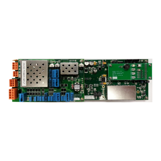
Page 7: Major Internal Hardware Components
Description Major Internal Hardware Components Note: Shown as supplied by Biomark. Exciter Board Mother Board LED User Interface Board (optional) Note: Shown with sample enclosure. IS1001 Reader User Manual... -
Page 8: Mother Board And Led User Interface Board
(OFF+) or reduced (OFF-). The LED User Interface Board incorporates IS1001 status LEDs, an IS1001 beeper with a potentiometer to adjust its volume, and an IS1001 reset button. -
Page 9: Exciter Board
Remote Communication Board The Remote Communication Board incorporates the Ethernet and fiber optic communication interface and enables remote access to the connected IS1001 reader for data collection and reader configuration. The board contains two jumpers to enable each individual communication port. It is recommended to use only one communication port at a time, to avoid communication conflicts. -
Page 10: Usb Data Logger Board
USB flash drive. The board contains IS1001 status LEDs, an IS1001 beeper, and an IS1001 reset button. For information on using this board, see IS1001 USB Data Logger User Manual. -
Page 11: Ble Data Logger Board
The BLE (Bluetooth Low Energy) Data Logger Board stores tag IDs and diagnostics data it receives from the attached IS1001 reader to its internal flash memory. It has the capacity to store 1,024,000 tag IDs and 55,296 short status reports. -
Page 12: Installing And Configuring Is1001 Reader
IS1001 Reader Specifications section on page 2). During operation, IS1001 will turn itself off if supply voltage level goes outside of acceptable range by 2 V (by 1 V for IS1001-12V) and will turn itself back on once the level returns to normal. - Page 13 Installing and Configuring IS1001 Reader Pin 1 Pin 2 Pin 3 5. Make the antenna connection to the IS1001 reader. • Connect the antenna leads to pins 1 (+) and 4 (-) of the 4-pin “ANTENNA” connector J8 on the Exciter Board.
-
Page 14: Synchronizing Multiple Is1001 Readers
Bookmark not defined. for details. Synchronizing Multiple IS1001 Readers If you are employing two or more IS1001 readers at your site and either of the following conditions is true, you must synchronize the antenna exciter oscillators of the IS1001 readers in order to avoid interference between their antennas. - Page 15 4. 120 Ohm termination resistor needs to be connected between Pin 1 (SS+) and Pin 2 (SS-) of connector J7 on the Exciter Board of the two IS1001 readers that are closest to each end of the synchronization cable. This is accomplished by installing jumper JP2 on the Exciter Board of each of the two IS1001 readers.
- Page 16 Master reader becomes inactive or fails. 10. If you wish to have a certain IS1001 reader to always act as a Master and the rest as Slaves, so that you can activate or deactivate the entire site by activating or deactivating the Master...
-
Page 17: Real-Time Clock Synchronization Process
3. Use BioTerm to establish a connection with the IS1001 reader. For information on establishing a connection, see page 19. 4. If necessary, set the proper IS1001 reader’s date and time settings by using the RDS and the RTS commands (see page 28). - Page 18 The IS1001 reader will report the results of the entire tuning process and, if successful, will switch into Scan mode. The reader will select the capacitors setting that produced the highest antenna current as the initial tuning capacitance setting that will be used as the origination setting every time the reader is powered up or reset.
-
Page 19: Antenna Dynamic Tuning
Antenna output power (current) can be adjusted by changing exciter voltage (VE Level) on standard 24 V DC IS1001 readers. There are five steps of exciter voltage adjustments: from 12 V DC to 20 V DC in 2 V increments. Therefore, setting “1” adjusts the exciter voltage to 12 V DC (the minimum antenna power) and setting “5”... -
Page 20: Over-Temperature Protection
+65°C is detected. If the temperature reaches +75°C IS1001 reader will automatically switch into Standby mode to reduce the amount of heat it is generating and will switch back into Scan mode once the temperature drops below +70°C. -
Page 21: Detecting And Capturing Tag Ids
Detecting and Capturing Tag IDs Detecting and Capturing Tag IDs When the IS1001 reader is powered on or reset it will automatically start in Scan mode and will immediately begin scanning for tags. Depending on the configuration, detected tag IDs may be stored in up to 5 locations: •... -
Page 22: Tag Detection Counter
See BLE Data Logger User Manual for details on collecting data. Tag Detection Counter The tag detection counter shows the number of tag IDs that have been detected since the IS1001 reader was powered on or since the counter was reset. -
Page 23: Establishing Connection With Is1001 Reader
Communication Port. By default, the tag IDs, alarms, messages, and automatic reports are sent by the IS1001 reader to both of its communication ports. Only what type of data is sent to the Local Port can be customized by using CAL, CML, and CTL commands. -
Page 24: Ascii Protocol
Terminal, HyperTerminal, Tera Term Pro, ProComm, PuTTY, etc. Biomark recommends using BioTerm and BioStat programs to securely monitor, maintain, and update an IS1001 reader. For more details refer to BioTerm and BioStat User Manual, available at: http://www.biomark.com/help/manuals___instructions/. The BioTerm and BioStat programs are available for download at: http://www.biomark.com/help/firmware___applications/. -
Page 25: Usb Port Operation
Note: BioTerm or BioStat and the proper driver must be installed on your computer. If your computer is missing these programs, see the Pre-Installation Steps section on page 8. 1. Connect the IS1001 reader to a local computer using a USB type A-to-mini USB type B cable (not supplied). -
Page 26: Fiber Optic Port Operation
4. In the BioTerm or BioStat Serial Port box, select the serial port number you identified in the previous step. 5. In the Baud Rate box, make sure you match the IS1001 reader’s Remote Port speed setting that is fixed to 115200. -
Page 27: Ethernet Port Operation
• Connection type = TCP/IP If connection problems persist or if the IS1001 reader is not shown in the list of found devices, use the Lantronix DeviceInstaller utility to reconfigure the IS1001 reader’s XPort Ethernet module (described in the Configuring the IS1001 Reader’s Ethernet Settings section on page 25). - Page 28 IS1001 Reader Ethernet Port Operation 5. To verify the connection between the computer and the IS1001 reader, within BioTerm or BioStat Traffic window type ? and then press Enter. A list of available commands should be displayed. All the commands are described in detail on page 28.
-
Page 29: Configuring Ethernet Settings
Ethernet connection to the IS1001 reader. The module has been pre-configured by Biomark prior to shipping so IS1001 reader is ready to be connected to a LAN upon installation. Changes may be necessary, however, if a firmware upgrade becomes available for the Lantronix XPort module or if your local network requires changes to the configuration. -
Page 30: Assigning Static Ip Address To Is1001 Reader
When you first connect the IS1001 reader to your network it will typically be assigned a random IP address based on your network addressing scheme. Depending on your network configuration, this IP address may change each time you power the IS1001 reader off and on. To assign the IS1001 reader a static IP address: 1. -
Page 31: Configuring Ethernet Module Settings
Important! Only experienced and qualified network administrators should attempt to modify any of the IS1001 reader’s Ethernet configuration settings. 1. In the left-hand pane, select the IS1001 reader’s XPort module by clicking on its IP address. 2. In the right-hand pane, select the Web Configuration tab. -
Page 32: Commands
Commands Commands The IS1001 reader commands are made up of three or more characters followed by a carriage return, as illustrated in the following example: ACL1.0 Generally, the first three letters designate the command group and the remaining letters/digits designate the command parameters. The commands are not case sensitive. The backspace key can be used to correct an improper command. - Page 33 This specifies how long to wait before rebroadcasting a persistent alarm. For example, if Alarm Unique Delay = 60 and the capacitance low alarm is triggered, the IS1001 reader will wait 60 seconds before resending the alarm. If the alarm condition clears and then reappears, the new alarm will be sent without delay.
- Page 34 Note: In low Q systems you might set the Phase Deviation rather high (10 or more). But beware of setting the deviation value so high that the IS1001 reader is not making any adjustments at all or so low that the reader is not able to maintain the tune point.
- Page 35 The detection counter counts detected tag IDs and depends on the Detection Unique Mode settings. It does not count Virtual Test Tag detections. It resets to 0 whenever the IS1001 reader resets, powers up, or you activate the Reset option.
- Page 36 The delay can be set from 0 (disabled) to 1440 minutes (24 hours). When the delay expires the Virtual Test Tag will be activated for up to 120 milliseconds, unless the IS1001 reader has detected the presence of a real PIT tag at its antenna, in which case the Virtual Tag Test will be aborted and skipped.
- Page 37 • Last 1: The following occurs only if the tag ID is different from the tag ID previously detected by the IS1001 reader: The tag ID is sent to the communication ports, is stored in memory, is counted by the detection counter, and is accompanied by a beeper sound (if these features are enabled).
- Page 38 – 200. Default is 110. Memory Download Entire Memory Initiates the download of all data contained in the IS1001 reader’s memory. The Esc key can be used to cancel the process. Note: The data will be sent only to the port from which the memory download was requested.
- Page 39 The delay time is calculated by multiplying the IS1001’s Reader ID by 1 second. {01-FF} Set Reader ID in HEX Sets the distinctive ID for this IS1001 reader. The ID is a hexadecimal value in the range 01 – FF. Default is 01. {0-10000} Set Reader Idling Time in Milliseconds...
- Page 40 Master, Secondary Master, Slave and Standalone. Default is Secondary Master. If set to Master, the IS1001 reader will use its own antenna exciter oscillator as the source of the synchronization signal and will transmit it out to the synchronization network. If the unit is put in standby mode its synchronization output signal is disabled.
- Page 41 (switching back to Scan). Default values are 16 V and 18 V respectively. {HH:MM:SS} Set Reader Time (24-hour) Sets the IS1001 reader’s real-time clock present time. The time is specified as hh:mm:ss (hours:minutes:seconds) in 24-hour format. Reports Report Diagnostic Data Reports the IS1001 reader’s vital diagnostics information.
- Page 42 Note: The data will be sent only to the port from which the report was requested. {0-1440} Set Automatic Status Report Delay in Minutes Specifies how often to automatically send the Full Status Report. Valid values are 0 (disabled), 1 – 1440 minutes. Default is 60 minutes. IS1001 Reader User Manual...
-
Page 43: Reports Structures
Reports Structures Reports Structures Full Status Report Structure A full status report contains important configuration settings and diagnostic data for the IS1001 reader. The report can be generated using the RFS command. Status Message Message Information Reader Reader ID setting in HEX (01-FF) - Page 44 Detection counter value Tags in Memory Number of tag IDs presently stored in memory and percentage of memory used Status Reports in Memory Number of short status reports presently stored in memory and percentage of memory used IS1001 Reader User Manual...
- Page 45 Tuning Capacit. Low Alarm: Alarms Unique Delay: 3600 sec Antenna/Tuning: Exciter Voltage Level: Dynamic Tuning: Enabled Tuning Target Phase: Tuning Target Phase Deviation Threshold Communication: Local Port Speed: 115200 Tags To Local Port: Enabled Alarms To Local Port: Enabled IS1001 Reader User Manual...
-
Page 46: Short Status Report Structure
A short status report contains dynamic diagnostic parameters’ information for the IS1001 reader. It is generated every time an automatic status report is generated. This report is stored in IS1001 reader’s internal memory (if Save Status Reports to Memory (MSR) setting is enabled) in a form of comma separated data values string. - Page 47 2 = N/A 1 … 5 1 … 5 Exciter Voltage Level Exciter voltage level, 1 = lowest, 5 = highest (Always reports 1 for model IS1001-12V) -500 ... 500 Tuning Relative Phase -500 ... 500 Measured tuning relative phase 0 …...
-
Page 48: Noise Report Structure
162 mV (18%) Time Averaged Over: 0:01:00 INF: End Of Noise Report Diagnostic Data Report Structure A Diagnostic Data report contains important diagnostic information for the IS1001 reader. The report can be generated using the RDD command. Status Message Message Information Reader... - Page 49 Antenna Current: 2.1 A Tuning Capacitors: Tuning Phase: Tuning Relative Phase: FDXB Signal Level: 91 mV (10%) Temperature: 27.3 C Sync. Input Present: Sec. Master Active: Active Alarms: No Active Alarms INF: End Of Diagnostic Data Report IS1001 Reader User Manual...
-
Page 50: Alarm Messages And Codes
Alarm Messages and Codes Alarm Messages and Codes When an abnormal condition is detected by the IS1001 reader it generates an alarm message that is sent to the communication ports. The alarms are sent to all available ports (unless the CML0 command has been issued, in which case the alarms will not be sent to the local USB port.) - Page 51 +65°C and is approaching the manufacturer‘s specified operation limit of +70°C. Sync. Input Not Present IS1001 reader is set to operate as a Slave and has not detected the input synchronization signal. Verify that the Master IS1001 reader is working properly. Verify that the synchronization wiring is intact.
-
Page 52: Self-Tests And Diagnostics
If the antenna current exceeds 11 A peak-to-peak even when the minimal exciter voltage setting is applied, the IS1001 reader will switch itself into standby mode until it is either reset or toggled back to Scan mode. -
Page 53: Troubleshooting
1. Check the power supply connection and integrity. 2. Check the IS1001 reader’s power connection and integrity. 3. If problem is not resolved, the IS1001 reader must be sent to the manufacturer for repair. No Antenna Connection Detected 1. Check the antenna’s connection and integrity. -
Page 54: Maintenance
• If optional USB Data Logger Board is used for IS1001 data collection, periodically download the data or replace the flash drive before it becomes full (see IS1001 USB Data Logger User Manual). Warning! Do not remove the USB flash drive while data is being written to it. To safely remove the USB flash drive, use the Eject External Storage button. -
Page 55: Advanced Diagnostics
Advanced Diagnostics Warning! Only qualified service personnel should access the internal components of the IS1001 reader or perform the advanced diagnostics described in this section. The advanced diagnostics described in this section can be performed with the help of an oscilloscope. -
Page 56: Signals Examples
IS1001 Reader Advanced Diagnostics Signals Examples IS1001 Reader FDX-B Signal • No noise • No tag • 0.5ms per div IS1001 Reader FDX-B Signal • No noise • No tag • 1.0 ms per div IS1001 Reader FDX-B Signal •... - Page 57 Advanced Diagnostics IS1001 Reader FDX-B Signal • Noise • 1.0ms per div IS1001 Reader FDX-B Signal • Noise • 2.0ms per div IS1001 Reader FDX-B Signal • • 0.5ms per div IS1001 Reader User Manual...
- Page 58 IS1001 Reader Advanced Diagnostics IS1001 Reader FDX-B Signal • • 1.0ms per div IS1001 Reader Signal • No noise • No tag • 2.0ms per div IS1001 Reader Signal • No noise • No tag • 5.0ms per div IS1001 Reader User Manual...
- Page 59 Advanced Diagnostics IS1001 Reader Signal • 134KHz noise • 2.0ms per div IS1001 Reader Signal • 134KHz noise • 5.0ms per div IS1001 Reader Signal • • 2.0ms per div IS1001 Reader User Manual...
- Page 60 IS1001 Reader Advanced Diagnostics IS1001 Reader Signal • • 5.0ms per div IS1001 Reader User Manual...
-
Page 61: Updating Firmware
All settings may be reset to manufacturer default values during the update process, so it is recommended that you take a note of the present settings prior to updating the IS1001 reader. New or updated firmware may periodically become available for IS1001 reader. To update the firmware: 1. - Page 62 Updating Firmware 6. In the confirmation dialog, click on the OK button. The firmware update process should take less than a minute to complete. 7. Wait for the update process to finish. IS1001 Reader User Manual...
- Page 63 Updating Firmware 8. In the Application Update – Success dialog, click on the OK button. IS1001 Reader User Manual...
-
Page 64: Index
Remote Communication Board, 5 Diagnostics, 48, 51 Report structures, 39 Downloading tag IDs, 18 Sample signals, 52 Establishing a connection with the IS1001 Reader, 19 Scanning for tags, 17 Ethernet port, 19 Self-tests, 48 Ethernet port jumper, 5 Short status report, 42... - Page 65 Biomark, Inc. 705 S. 8th Street Boise, Idaho 83702, USA 1-208-275-0011 www.biomark.com customerservice@biomark.com IS1001 Reader User Manual...
Need help?
Do you have a question about the IS1001 and is the answer not in the manual?
Questions and answers