GE LOGIQ V2 User Manual
Hide thumbs
Also See for LOGIQ V2:
- Technical publication (127 pages) ,
- Basic service manual (317 pages)

Related Manuals for GE LOGIQ V2


Summary of Contents for GE LOGIQ V2
- Page 1 Technical Publication Direction 5610736-100 Rev. 9 LOGIQ V2/LOGIQ V1 User Guide R1.X.X Operating Documentation Copyright 2015-2017 By General Electric Co.
- Page 2 This product complies with regulatory requirements of the following European Directive 93/42/EEC concerning medical devices. This manual is a reference for the LOGIQ V2, LOGIQ V1. It applies to all versions of the R1.x.x for the LOGIQ V2/LOGIQ V1 ultrasound system.
- Page 3 MyWorkshop/ePDM (GE Electronic Product Data Management). If you need to know the latest revision, contact your distributor, local GE Sales Representative or in the USA call the GE Ultrasound Clinical Answer Center at 1 800 682 5327 or 1 262 524 5698.
- Page 4 This page intentionally left blank. – LOGIQ V2/LOGIQ V1 User Guide Direction 5610736-100 Rev. 9...
- Page 5 The location of the CE marking is shown in the safety chapter of this manual. Authorized EU Representative European registered place of business: GE Medical Systems Information Technologies GmbH (GEMS IT GmbH) Munzinger Strasse 5, D-79111 Freiburg, Germany Tel: +49 761 45 43 -0; Fax: +49 761 45 43 -233 –...
- Page 6 FDA (Food and Drug Administration, Department of Health, USA). Certifications • General Electric Medical Systems is ISO 13485 certified. Original Documentation • The original document was written in English. – LOGIQ V2/LOGIQ V1 User Guide Direction 5610736-100 Rev. 9...
- Page 7 Country-Specific Approval • JAPAN Certified Number: Importer Information • Turkey – LOGIQ V2/LOGIQ V1 User Guide Direction 5610736-100 Rev. 9...
- Page 8 – LOGIQ V2/LOGIQ V1 User Guide Direction 5610736-100 Rev. 9...
- Page 9 Archive Screen (For R1.1.x)- - - - - - - - - - - - - - - - - - - - - - - - - - - - - - - 1-62 – LOGIQ V2/LOGIQ V1 User Guide...
- Page 10 Defining Hot Keys - - - - - - - - - - - - - - - - - - - - - - - - - - - - - - - - - - - - - - 2-67 – LOGIQ V2/LOGIQ V1 User Guide...
- Page 11 Contact Information Contacting GE Ultrasound - - - - - - - - - - - - - - - - - - - - - - - - - - - - - - - - 3-73 Manufacturer - - - - - - - - - - - - - - - - - - - - - - - - - - - - - - - - - - - - - - - - - 3-79 Chapter 4 —...
- Page 12 Maintenance - - - - - - - - - - - - - - - - - - - - - - - - - - - - - - - - - - - - - - - - - 6-39 Index i-10 – LOGIQ V2/LOGIQ V1 User Guide Direction 5610736-100 Rev. 9...
- Page 13 Chapter 1 Getting Started Console Overview, Moving the System, System Start-up, Probes and Beginning an Exam – LOGIQ V2/LOGIQ V1 User Guide Direction 5610736-100 Rev. 9...
- Page 14 NOTE: The system color varies. The LOGIQ V2/LOGIQ V1 manuals are written for users who are familiar with basic ultrasound principles and techniques. They do not include sonographic training or detailed clinical procedures.
- Page 15 The screen graphics in this manual are only for illustrational purposes. Actual screen output may differ with the different software versions. NOTE: The Electronic Documentation CD includes English and all translations. – LOGIQ V2/LOGIQ V1 User Guide Direction 5610736-100 Rev. 9...
- Page 16 Intended Use The LOGIQ V2/LOGIQ V1 is intended for use by a qualified physician for ultrasound evaluation. – LOGIQ V2/LOGIQ V1 User Guide Direction 5610736-100 Rev.
- Page 17 Overview Indications for Use The LOGIQ V2/LOGIQ V1 is intended for ultrasound imaging, measurement and analysis of the human body for multiple clinical applications including: Fetal/OB; GYN; Abdominal; Pediatric; Small Organ (breast, testes, thyroid); Neonatal and Adult Cephalic; Cardiac (adult & pediatric); Peripheral Vascular;...
- Page 18 CAUTION jurisdictions restrict certain uses, such as gender determination. Contraindication The LOGIQ V2/LOGIQ V1 ultrasound system is not intended for ophthalmic use or any use causing the acoustic beam to pass through the eye. Prescription Device CAUTION: United States law restricts this device to sale or use by, or on the order of a physician.
- Page 19 Information’ on page 3-73 for more information. Perform regular preventive maintenance. See ‘System Care and Maintenance’ on page 3-36 for more information. The LOGIQ V2/LOGIQ V1 does not contain any operator serviceable internal components. Ensure that unauthorized personnel do not tamper with the unit.
- Page 20 Do not operate the system in the vicinity of a heat source, of CAUTION strong electric or magnetic fields (close to a transformer), or near instruments generating high-frequency signals, such as HF surgery. These can affect the ultrasound images adversely. – LOGIQ V2/LOGIQ V1 User Guide Direction 5610736-100 Rev. 9...
- Page 21 Plug and Outlet Configuration NOTE: Country-specific power cords are currently available for Argentina, Australia/New Zealand, China, Denmark, India/South Africa, Switzerland, United Kingdom, Europe, the United States, Israel, Brazil and Japan. – LOGIQ V2/LOGIQ V1 User Guide Direction 5610736-100 Rev. 9...
- Page 22 Operating Environment Ensure that there is sufficient air flow around the ultrasound unit when installed in a fixed location. Do not cover the ventilation holes of the LOGIQ V2/LOGIQ V1. CAUTION The LOGIQ V2/LOGIQ V1 system and probe connector are not CAUTION waterproof.
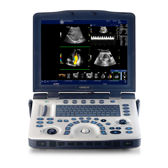
- Page 23 Overview Console Graphics The following are illustrations of the console: Figure 1-2. LOGIQ V2/LOGIQ V1 System - an example 1. Handle 2. LCD 3. Primary Menu keys 4. Alphanumeric keys 5. Control Panel – 1-11 LOGIQ V2/LOGIQ V1 User Guide...
- Page 24 Getting Started Console Graphics (continued) Figure 1-3. LOGIQ V2/LOGIQ V1 System Do not push objects into air vents and openings of LOGIQ V2/ CAUTION LOGIQ V1. Doing so can cause fire or electric shock by shorting out interior components. DO NOT touch the patient and any of the connectors on the...
- Page 25 The lithium ion battery provides power when an AC power source is not available. A battery in the battery bay is standard with the LOGIQ V2/LOGIQ V1. Lithium ion batteries last longer than conventional batteries and do not require replacement as often.
- Page 26 Do not solder a battery. • Do not connect the battery to an electrical power outlet. If the LOGIQ V2/LOGIQ V1 is not being used on a monthly WARNING basis, the battery needs to be removed during the lengthy non-use period.
- Page 27 A full discharge/charge cycle means the system is turned on using battery power until the battery loses its charge completely and the system shuts down. Plug the LOGIQ V2/LOGIQ V1 in until the battery is fully charged as indicated by a green LCD light.
- Page 28 If the battery is in charge, the battery icon appears as being charged in the system status bar. Figure 1-7. Charging Battery icon Select the battery icon and the following information window appears: Figure 1-8. Battery Status Message 1-16 – LOGIQ V2/LOGIQ V1 User Guide Direction 5610736-100 Rev. 9...
- Page 29 1 minute. This protects the whole system. You need to charge the battery immediately before the system shuts down or you may lose useful information. – 1-17 LOGIQ V2/LOGIQ V1 User Guide Direction 5610736-100 Rev. 9...
- Page 30 5. Disconnect AC power cable to use the battery to supply power to the system. If it is still error, shutdown the system, disconnect AC power cable if it is connected, remove the battery and contact GE Service. 1-18 –...
- Page 31 Figure 1-13. Place the battery on the bottom cover 3. Push the battery completely into the box until the battery is locked and the battery lock is in the lock position. Figure 1-14. Lock the battery – 1-19 LOGIQ V2/LOGIQ V1 User Guide Direction 5610736-100 Rev. 9...
- Page 32 Figure 1-15. Unlock and push the battery 3. When the battery is released from the lock, remove it from the battery box. Figure 1-16. Remove the battery 1-20 – LOGIQ V2/LOGIQ V1 User Guide Direction 5610736-100 Rev. 9...
- Page 33 Place the AC adapter in a ventilated area, such as a desk, when you use it to run LOGIQ V2/LOGIQ V1. Do not cover the AC adapter with paper or other items that will reduce cooling; do not use the AC adapter inside a carrying case.
- Page 34 Getting Started Peripheral/Accessory Connector Panel LOGIQ V2/LOGIQ V1 peripherals and accessories can be properly connected using the connector panel. Each outer (case) ground line of peripheral/accessory CAUTION connectors are Earth Grounded. Signal ground lines are Not Isolated. For compatibility reasons, use only GE-approved probes, CAUTION peripherals, or accessories.
- Page 35 9. 2 general USB ports — USB Flash Drive, USB HDD, DVD-RW, Footswitch, Wireless Lan Adapter 10. 1 SD Card port 11. 1 Probe Connector Port 12. Probe Connector Locking Lever – 1-23 LOGIQ V2/LOGIQ V1 User Guide Direction 5610736-100 Rev. 9...
- Page 36 1. Connect the printer to the system. The printer can be properly connected using the Isolated USB printer port. Table 1-2: Printers Connection Printers Illustration Sony UP-D897 printer Sony UP-D898MD printer 1-24 – LOGIQ V2/LOGIQ V1 User Guide Direction 5610736-100 Rev. 9...
- Page 37 Overview Table 1-2: Printers Connection Printers Illustration Sony UP-D25MD printer HP Officejet 100 printer HP Officejet Pro 8100 printer – 1-25 LOGIQ V2/LOGIQ V1 User Guide Direction 5610736-100 Rev. 9...
- Page 38 Note: Do not connect the DVD-RW to the system while scanning. Note: Be sure the 2 connectors on the USB Y cable are connected to the system at the same time. 1-26 – LOGIQ V2/LOGIQ V1 User Guide Direction 5610736-100 Rev. 9...
- Page 39 Overview Table 1-3: Peripherals Connection Peripherals Illustration Wireless Card USB Flash Drive USB Hard Disk – 1-27 LOGIQ V2/LOGIQ V1 User Guide Direction 5610736-100 Rev. 9...
- Page 40 Getting Started Peripherals Connection (continued) 3. Other peripheral ports connection Table 1-4: Other Peripheral ports connection Peripherals Illustration SD Card connection Ethernet connection HDMI port connection 1-28 – LOGIQ V2/LOGIQ V1 User Guide Direction 5610736-100 Rev. 9...
- Page 41 NOTE: Please refer to the manufacture’s operation manual of each peripheral for information needed by the user to operate the peripheral safely. – 1-29 LOGIQ V2/LOGIQ V1 User Guide Direction 5610736-100 Rev. 9...
- Page 42 Getting Started Attaching the Security Cable To ensure that the LOGIQ V2/LOGIQ V1 is not removed from the premises, attach the security cable. 1. Wrap the cable around an immovable object. Figure 1-18. Security Cable 2. Be sure to rotate the key to the unlocked position (to the right).
- Page 43 Overview Set Up Wired Footswitch Use only the GE recommended footswitch. The footswitch may be used as select keys. You can attach this Footswitch to the system by connecting it to the USB port on the system. You can configure its functionality via the Utility ->...
- Page 44 21. Measure key 11. Worksheet key 22. Body Pattern key Do not apply too much force when adjusting the TGC slide pots CAUTION as this could damage the slide pots. 1-32 – LOGIQ V2/LOGIQ V1 User Guide Direction 5610736-100 Rev. 9...
- Page 45 Report, Scan Coach, CF and PDI are option features for the system, after the options are installed on the system, use the key caps in the option kits to replace the blank key caps. – 1-33 LOGIQ V2/LOGIQ V1 User Guide Direction 5610736-100 Rev. 9...
- Page 46 Press Next to display the next group of Primary Menu. The Primary Menu can be configured in Utility -> Application -> Image Controls -> Primary Menu. 1-34 – LOGIQ V2/LOGIQ V1 User Guide Direction 5610736-100 Rev. 9...
- Page 47 Pressing Freeze a second time continues live image data acquisition. • To activate a specific mode, press the mode assigned rotary key. – 1-35 LOGIQ V2/LOGIQ V1 User Guide Direction 5610736-100 Rev. 9...
- Page 48 (e.g. to fix a measurement caliper). • The Trackball is used with almost every key function in this group. Trackball control depends on the last key function pressed. 1-36 – LOGIQ V2/LOGIQ V1 User Guide Direction 5610736-100 Rev. 9...
- Page 49 11. Caps Lock: (lit when on), network connection 24. Depth Scale indicator (PC=connected, PC with X=not 25. Focal Zone Indicator connected), Battery Icon/Plug Icon, InSite 26. Body Pattern status, InSite controls 12. Current date and time – 1-37 LOGIQ V2/LOGIQ V1 User Guide Direction 5610736-100 Rev. 9...
- Page 50 Set to select the image. 3. Place the cursor on the Delete icon and press Set. A warning message is displayed asking the user to confirm the action to perform. 4. Select Yes. 1-38 – LOGIQ V2/LOGIQ V1 User Guide Direction 5610736-100 Rev. 9...
- Page 51 Save As menu Activate Save As feature. Number of Images in Exam The number of images in an exam is tracked on the bottom of these Monitor Display Controls. – 1-39 LOGIQ V2/LOGIQ V1 User Guide Direction 5610736-100 Rev. 9...
- Page 52 DO NOT scratch or press on the panel with any sharp objects, such as a pencil or pen, as this may result in damage to the panel. NOTE: Bright light could impact readability of screen. 1-40 – LOGIQ V2/LOGIQ V1 User Guide Direction 5610736-100 Rev. 9...
- Page 53 The brightness of the LCD monitor should be set first as it affects the Gain and Dynamic Range settings of your image. Once set, this should not be changed unless the brightness of your scanning environment changes. – 1-41 LOGIQ V2/LOGIQ V1 User Guide Direction 5610736-100 Rev. 9...
- Page 54 Getting Started Volume To adjust the volume: On the alphanumeric keyboard, adjust volume with the Fn + Up/ Down keys Figure 1-29. Volume 1. Volume 1-42 – LOGIQ V2/LOGIQ V1 User Guide Direction 5610736-100 Rev. 9...
- Page 55 4. Store all probes in their original cases or in soft cloth or foam to prevent damage. 5. Store sufficient gel and other essential accessories in the special storage case. – 1-43 LOGIQ V2/LOGIQ V1 User Guide Direction 5610736-100 Rev. 9...
- Page 56 ‘Before moving the system’ on page 1-43 for more information), also perform the following: 1. Before transporting, place the system in its special storage case. 2. Ensure that the system is firmly secured while inside the vehicle. 1-44 – LOGIQ V2/LOGIQ V1 User Guide Direction 5610736-100 Rev. 9...
- Page 57 NOT have other equipment operating on the same circuit. Voltage level check Check the rating label on the bottom of the system. Check the voltage range indicated on the label. – 1-45 LOGIQ V2/LOGIQ V1 User Guide Direction 5610736-100 Rev. 9...
- Page 58 Argentina, Australia/New Zealand, China, Denmark, India/South Africa, Switzerland, United Kingdom, Europe, the United States, Israel, Brazil and Japan. Acclimation Time Table 1-5: System Acclimation Time Chart Degree C Degree F hours 1-46 – LOGIQ V2/LOGIQ V1 User Guide Direction 5610736-100 Rev. 9...
- Page 59 To avoid leakage current above safety limits as prescribed by CAUTION IEC 60601-1 and to ensure continuity of protective earth. Only connect LOGIQ V2/LOGIQ V1 and mains-operated accessories to the appropriate wall outlet. DO NOT connect them to a single or multiple socket outlets, an extension cord, power strip or an adapter plug.
- Page 60 2. Momentarily press the On/Off switch to turn the power on. 3. The system should now go through its boot-up process with no further user intervention. Figure 1-32. Power On/Off Switch Location 1-48 – LOGIQ V2/LOGIQ V1 User Guide Direction 5610736-100 Rev. 9...
- Page 61 If no probe is connected, the system goes into freeze mode. • Peripheral devices are activated on power up. After initialization is complete, the default B-Mode screen is displayed on the monitor (if a probe is connected). – 1-49 LOGIQ V2/LOGIQ V1 User Guide Direction 5610736-100 Rev. 9...
- Page 62 The keyboard backlight is lit for operation in dimly lit room. Login Personal IDs and associated passwords can be preset in Utility -> Admin -> Users on the LOGIQ V2/LOGIQ V1. If the User Auto Logon preset in Utility -> Admin -> Logon is blank, you are prompted to login.
- Page 63 Connect the AC adapter mains plug to the outlet if the system needs to be charged and then disconnect it when the system has been fully charged. – 1-51 LOGIQ V2/LOGIQ V1 User Guide Direction 5610736-100 Rev. 9...
- Page 64 Sleep Mode after the monitor goes black. Sleep mode is not intended to replace the shutdown process. WARNING The system should be fully shutdown every day. 1-52 – LOGIQ V2/LOGIQ V1 User Guide Direction 5610736-100 Rev. 9...
- Page 65 1. Enter Utility -> System -> General -> Date/Time. 2. Reset the system date and time. 3. Select Apply and then select OK. 4. Select Save. – 1-53 LOGIQ V2/LOGIQ V1 User Guide Direction 5610736-100 Rev. 9...
- Page 66 2. Carefully remove the probe and unwrap the probe cord. DO NOT allow the probe head to hang free. Impact to the CAUTION probe head could result in irreparable damage. 1-54 – LOGIQ V2/LOGIQ V1 User Guide Direction 5610736-100 Rev. 9...
- Page 67 3. Align the connector with the probe port and carefully push into place with the cable facing the front of the system. Figure 1-35. Probe connection to LOGIQ V2/LOGIQ V1 4. Flip the connector locking lever up. Figure 1-36. Probe connector locking lever 5.
- Page 68 2. Pull the probe connector straight out of the probe port carefully. 3. Ensure the cable is free. 4. Be sure that the probe head is clean before placing the probe in its storage box or wall hanging unit. 1-56 – LOGIQ V2/LOGIQ V1 User Guide Direction 5610736-100 Rev. 9...
- Page 69 Probes 2-Probe Port Adapter (option) Mounting 2-Probe Port Adapter to LOGIQ V2/LOGIQ V1 1. Turn over LOGIQ V2/LOGIQ V1 and 2-Probe Port Adapter to let the back upward. Figure 1-37. 2-Probe Port Adapter connection, Step 1 2. Align the 2 location pins of 2 Probe Port Adapter with the location holes of LOGIQ V2/LOGIQ V1 and carefully push into place, then screw 3 screws.
- Page 70 Getting Started Mounting 2-Probe Port Adapter to LOGIQ V2/LOGIQ V1 (continued) 3. Flip the connector locking lever down. Figure 1-39. 2-Probe Port Adapter connection, Step 3 4. Turn over the system with 2-Probe Port Adapter, now the 2-Probe Port Adapter is connected successfully.
- Page 71 2-Probe Port Adapter. Figure 1-41. 2-probe Port Adapter connection, Step 5 Selecting the probe Press Patient or Preset on the control panel to select the probe. Figure 1-42. Select the probe – 1-59 LOGIQ V2/LOGIQ V1 User Guide Direction 5610736-100 Rev. 9...
- Page 72 3. Review: Select to review the image. 4. Thumbnail image: Provide a thumbnail image of current selected image. 5. Scan: Select to start scanning. 1-60 – LOGIQ V2/LOGIQ V1 User Guide Direction 5610736-100 Rev. 9...
- Page 73 10. Folder Information: Displays the Exam History of the selected patient. NOTE: Columns drive the ordering of the patients displayed. The colums that you select drives the order of the the displayed paient database. – 1-61 LOGIQ V2/LOGIQ V1 User Guide Direction 5610736-100 Rev. 9...
- Page 74 Make sure the correct patient identification appears on all screens and hard copy prints. Always use the minimum power required to obtain acceptable WARNING images in accordance with applicable guidelines and policies. 1-62 – LOGIQ V2/LOGIQ V1 User Guide Direction 5610736-100 Rev. 9...
- Page 75 In most cases, the operator sits/stands straight in front of the operator console and the patient lies on the bed on the right (or left) side of the system. – 1-63 LOGIQ V2/LOGIQ V1 User Guide Direction 5610736-100 Rev. 9...
- Page 76 The system permanently stores all images of the current patient. The system creates the new patient and the new folder to store all images in the archive screen. 1-64 – LOGIQ V2/LOGIQ V1 User Guide Direction 5610736-100 Rev. 9...
- Page 77 Figure 1-46. Patient Screen 1. Image Management 2. Function Selection 3. EZBackup/EZMove 4. Dataflow Selection 5. Scan 6. Patient Information 7. Category Selection 8. Exam Information 9. Patient View/Exam View – 1-65 LOGIQ V2/LOGIQ V1 User Guide Direction 5610736-100 Rev. 9...
- Page 78 “ ‘ \ / : ; . , * < > | + = [ ] & 6. Select Register. Enter Past OB Exam information, if desired. 7. Select the probe to start scanning (or select Esc, Scan, or Freeze). 8. Perform the exam. 1-66 – LOGIQ V2/LOGIQ V1 User Guide Direction 5610736-100 Rev. 9...
- Page 79 Permanent Store to store the images permanently. After completing the measurement, verify that the CAUTION measurement result window is updated before you send or save the image. – 1-67 LOGIQ V2/LOGIQ V1 User Guide Direction 5610736-100 Rev. 9...
- Page 80 Select the patient from the Patient List. Select Resume Exam to continue the last exam that was performed on the selected patient. Select New Exam to start a new exam on the selected patient. 1-68 – LOGIQ V2/LOGIQ V1 User Guide Direction 5610736-100 Rev. 9...
- Page 81 1. Select Patient on the control panel. 2. Select the patient from the Patient List. 3. Select New Exam. 4. A new exam is created. Enter the data and begin the scan. – 1-69 LOGIQ V2/LOGIQ V1 User Guide Direction 5610736-100 Rev. 9...
- Page 82 Delete All. Delete all the unsaved images, and then a new patient screen displays. d. Cancel. Do nothing with the unsaved data, and return to scanning. 1-70 – LOGIQ V2/LOGIQ V1 User Guide Direction 5610736-100 Rev. 9...
- Page 83 OK if you want to permanently store the images/ measurements that were just taken. 5. Enter the Active Images Screen, select Permanent Store. 6. Return to patient page, select New Patient. – 1-71 LOGIQ V2/LOGIQ V1 User Guide Direction 5610736-100 Rev. 9...
- Page 84 No to keep the current patient. b. Without Patient ID: Store All (Auto ID). Store the unsaved data to the patient that is auto created by the system. 1-72 – LOGIQ V2/LOGIQ V1 User Guide Direction 5610736-100 Rev. 9...
- Page 85 Cancel to do nothing with the unsaved data, and return to Archive page. 6. Cancel. Do nothing with the unsaved data, and return to Archive page. – 1-73 LOGIQ V2/LOGIQ V1 User Guide Direction 5610736-100 Rev. 9...
- Page 86 ?" Select OK to delete the unsave all temporary images iamges, select Cancel not to delete the images. 4. Cancel. Do nothing with the unsaved data, and return to Patient page. 1-74 – LOGIQ V2/LOGIQ V1 User Guide Direction 5610736-100 Rev. 9...
- Page 87 1. Store All All the unsaved images will be saved. The current patient doesn't have Patient ID, the system will indicate to enter patient ID. Figure 1-52. Enter Patient ID – 1-75 LOGIQ V2/LOGIQ V1 User Guide Direction 5610736-100 Rev. 9...
- Page 88 ?" Select OK to delete the unsave all temporary images iamges, select Cancel not to delete the images. 4. Cancel. Do nothing with the unsaved data, and return to Patient page. 1-76 – LOGIQ V2/LOGIQ V1 User Guide Direction 5610736-100 Rev. 9...
- Page 89 For R1.1.x software: To end a patient: Press Patient -> New Patient, then select Store All in the pop-up menus to store exam data. – 1-77 LOGIQ V2/LOGIQ V1 User Guide Direction 5610736-100 Rev. 9...
- Page 90 2. Select Exam View to display patient exam screen. 3. Select the exam to be deleted. 4. Select Delete. The confirmation dialog box displays. 5. Select OK to delete or Cancel. 1-78 – LOGIQ V2/LOGIQ V1 User Guide Direction 5610736-100 Rev. 9...
- Page 91 4. Select Active Images to display the image list. 5. Select the image to delete and select Delete. The confirmation dialog box displays. 6. Select Delete to delete or Cancel to cancel. – 1-79 LOGIQ V2/LOGIQ V1 User Guide Direction 5610736-100 Rev. 9...
- Page 92 Getting Started 1-80 – LOGIQ V2/LOGIQ V1 User Guide Direction 5610736-100 Rev. 9...
- Page 93 Chapter 2 Performing an Exam Optimizing the Image, Measurement and Analysis – LOGIQ V2/LOGIQ V1 User Guide Direction 5610736-100 Rev. 9...
- Page 94 Coded Harmonic Harmonic imaging utilizes Digitally Encoded Ultrasound (DEU). Imaging (CHI) Coded Harmonics enhances near field resolution for improved small parts imaging as well as far field penetration. – LOGIQ V2/LOGIQ V1 User Guide Direction 5610736-100 Rev. 9...
- Page 95 The colorize bar displays while Colorize is activated. – LOGIQ V2/LOGIQ V1 User Guide Direction 5610736-100 Rev. 9...
- Page 96 The quality of the resulting image is somewhat user-dependent and requires some additional skill and practice to develop proper technique and become fully proficient. LOGIQ View is only available in B mode. – LOGIQ V2/LOGIQ V1 User Guide Direction 5610736-100 Rev. 9...
- Page 97 Change the gradation of color map. Threshold Limits color flow overlay to low level echoes inside vessel walls. Helps minimize color `bleeding' outside vessel walls. Frame Average Averages color frames. – LOGIQ V2/LOGIQ V1 User Guide Direction 5610736-100 Rev. 9...
- Page 98 Q Analysis (Option) Q Analysis is available for the image loop acquired in the following modes: TVI, CF and PDI. All of the Q Analysis modes operate similarly, with some variation. – LOGIQ V2/LOGIQ V1 User Guide Direction 5610736-100 Rev. 9...
- Page 99 M-Mode image using velocity and variance color maps. The Color Flow wedge overlays the B-Mode image and M-Mode time line. See ‘Color Flow Mode Controls’ on page 2-5 for more information. – LOGIQ V2/LOGIQ V1 User Guide Direction 5610736-100 Rev. 9...
- Page 100 The angle steer function only applies to linear probes. Audio Volume Controls audio output. Invert Vertically inverts the spectral trace without affecting the baseline position. – LOGIQ V2/LOGIQ V1 User Guide Direction 5610736-100 Rev. 9...
- Page 101 Gather samples along (option) the entire Doppler beam for rapid scanning of the heart. Range gated CW allows information to be gathered at higher velocities. – LOGIQ V2/LOGIQ V1 User Guide Direction 5610736-100 Rev. 9...
- Page 102 NOTE: If the image stops before you’re done scanning, start acquiring the 3D volume of interest again. 6. To complete the 3D scan, press R (Right key). 2-10 – LOGIQ V2/LOGIQ V1 User Guide Direction 5610736-100 Rev. 9...
- Page 103 With a photograph, Read Zoom manipulates the negative and enlarges the picture; whereas Write Zoom uses a telephoto lens to bring the image closer before taking the picture. – 2-11 LOGIQ V2/LOGIQ V1 User Guide Direction 5610736-100 Rev. 9...
- Page 104 1. Zoom status 2. Reference Image To exit zoom, press B-Mode or press the Depth/Zoom/Ellipse knob again or rotate Depth/Zoom/Ellipse knob counterclockwise until the reference zoom image is removed. 2-12 – LOGIQ V2/LOGIQ V1 User Guide Direction 5610736-100 Rev. 9...
- Page 105 First use the Read Zoom (Press Zoom knob once) to get to the HINTS area of interest, then use Write Zoom (press Zoom knob again). – 2-13 LOGIQ V2/LOGIQ V1 User Guide Direction 5610736-100 Rev. 9...
- Page 106 (but not from the worksheet). Use the Trackball to start CINE after pressing Freeze. Activating CINE To activate CINE, 1. Press Freeze. 2. Move the Trackball. 2-14 – LOGIQ V2/LOGIQ V1 User Guide Direction 5610736-100 Rev. 9...
- Page 107 Clear key. • Press Set key on the control panel or Body Pattern key on the control panel to exit without erasing the body pattern. – 2-15 LOGIQ V2/LOGIQ V1 User Guide Direction 5610736-100 Rev. 9...
- Page 108 Arrow pointers can be used by activating the F2 (Arrow) key on the keyboard. When the pointer comes up, it is a GREEN color, indicating it is active and can be moved. 2-16 – LOGIQ V2/LOGIQ V1 User Guide Direction 5610736-100 Rev. 9...
- Page 109 Scan Coach IS MEANT TO PROVIDE REFERENCE MATERIAL FOR ACQUISITION, BUT IT IS NOT INTENDED TO IDENTIFY DIAGNOSTIC IMAGE QUALITY. ACTUAL IMAGES, INCLUDING IMAGE QUALITY, OF THE DEVICE MAY VARY VERSUS THE PROVIDED REFERENCE MATERIAL. – 2-17 LOGIQ V2/LOGIQ V1 User Guide Direction 5610736-100 Rev. 9...
- Page 110 YOU EXPRESSLY AGREE THAT USE OF Scan Coach AND/ OR ITS CONTENT IS AT YOUR SOLE RISK. TO THE FULLEST EXTENT PERMISSIBLE PURSUANT TO APPLICABLE LAW, GE AND ITS AFFILIATES DISCLAIM ALL WARRANTIES OF ANY KIND, WHETHER EXPRESS OR IMPLIED, INCLUDING WITHOUT LIMITATION ANY WARRANTY OF MERCHANTABILITY, FITNESS FOR A PARTICULAR PURPOSE OR NON-INFRINGEMENT.
- Page 111 The schema anime shows the key anatomical structures to be visualized in two dimensional mode. Scan Coach can be used as an on-demand refresher/reminder tool in live scanning. – 2-19 LOGIQ V2/LOGIQ V1 User Guide Direction 5610736-100 Rev. 9...
- Page 112 2. Press Patient key on the control panel to register a new patient. Then select the protocol from the pull-down menu, and then select Scan to navigate to the Scan Coach screen. Figure 2-3. Scan Coach Start 2-20 – LOGIQ V2/LOGIQ V1 User Guide Direction 5610736-100 Rev. 9...
- Page 113 Figure 2-4. Scan Coach Addendum Or select Cancel not to start Scan Coach. Check the box before Don’t show next time and the Scan Coach addendum won’t display next time. – 2-21 LOGIQ V2/LOGIQ V1 User Guide Direction 5610736-100 Rev. 9...
- Page 114 Performing an Exam Using Scan Coach (For R1.0.x) (continued) b. Then select the protocol from the list and select Start. Figure 2-5. Select protocol 2-22 – LOGIQ V2/LOGIQ V1 User Guide Direction 5610736-100 Rev. 9...
- Page 115 Active step. The box is green when the program is active or yellow when it is paused. h. Edit (Pencil Icon) Stop Pause or Resume k. In/Out Step – 2-23 LOGIQ V2/LOGIQ V1 User Guide Direction 5610736-100 Rev. 9...
- Page 116 Figure 2-7. Scan Coach Reference, Probe position and Schema Images 5. Complete the scan and make the measurements if necessary, press Store key to store the image and go to next step. 2-24 – LOGIQ V2/LOGIQ V1 User Guide Direction 5610736-100 Rev. 9...
- Page 117 Program Selections column. Then select Exit to the Scanning page. Figure 2-8. Select Scan Coach Protocol – 2-25 LOGIQ V2/LOGIQ V1 User Guide Direction 5610736-100 Rev. 9...
- Page 118 Figure 2-9. Scan Coach Addendum Or select Cancel not to start Scan Coach. Check the box before Don’t show next time and the Scan Coach addendum won’t display next time. 2-26 – LOGIQ V2/LOGIQ V1 User Guide Direction 5610736-100 Rev. 9...
- Page 119 If there is only one program in the current application, the system will display the Scan Coach screen directly. This step is only available when there are two or more programs. Figure 2-10. Scan Coach Start – 2-27 LOGIQ V2/LOGIQ V1 User Guide Direction 5610736-100 Rev. 9...
- Page 120 2. Select this icon to enter L1. 3. Select this icon to enter L2. 4. Select to Restart, Exit or Edit Scan Coach. 2-28 – LOGIQ V2/LOGIQ V1 User Guide Direction 5610736-100 Rev. 9...
- Page 121 4. Select program, for example, LIVER LENGTH, then select the button L1 or press REF key on the control panel to review the reference image. Figure 2-12. Using Scan Coach – 2-29 LOGIQ V2/LOGIQ V1 User Guide Direction 5610736-100 Rev. 9...
- Page 122 You can also press the button marked as 1 to return to the program step list. Figure 2-13. Using Scan Coach L1 2-30 – LOGIQ V2/LOGIQ V1 User Guide Direction 5610736-100 Rev. 9...
- Page 123 Figure 2-14. Using Scan Coach L2 a. live scan image b. reference image c. probe position d. two dimensional schema of the current scan plane – 2-31 LOGIQ V2/LOGIQ V1 User Guide Direction 5610736-100 Rev. 9...
- Page 124 Setting up Scan Coach (For R1.0.x) Go to Utility -> Scan / Assistant -> Scan Assistant Manager to create, import/export and manage the Scan Coach programs. Figure 2-15. Setting up scan coach 2-32 – LOGIQ V2/LOGIQ V1 User Guide Direction 5610736-100 Rev. 9...
- Page 125 Setting up Scan Coach (For R1.1.x) Go to Utility -> Scan Coach -> Scan Coach Manager to create, import/export and manage the Scan Coach programs. Figure 2-16. Setting up scan coach – 2-33 LOGIQ V2/LOGIQ V1 User Guide Direction 5610736-100 Rev. 9...
- Page 126 Edit Scan Coach Protocol 1. To edit Scan Coach protocols, • For R1.0.x, Go to Utility -> Scan / Assistant -> Scan Assistant Manager and select Creator, Figure 2-17. Scan Coach Manager 2-34 – LOGIQ V2/LOGIQ V1 User Guide Direction 5610736-100 Rev. 9...
- Page 127 For R1.1.x software, go to Utility -> Scan Coach -> Scan Coach Manager and select Creator. Figure 2-18. Scan Coach Manager Or Select the button marked as 4 in the program list. Figure 2-19. Program List – 2-35 LOGIQ V2/LOGIQ V1 User Guide Direction 5610736-100 Rev. 9...
- Page 128 Edit page. Figure 2-20. Edit the Protocol 2. The Scan Coach Creator is used to build customized programs that can be imported onto the LOGIQ V2/LOGIQ V1. Select Scan Coach on the tool bar to display the Scan Coach edit page.
- Page 129 “Reference Images” of the corresponding application. Then select Close after the upload is complete. NOTE: The reference image only supports *.dcm file. Figure 2-23. Upload Reference Image – 2-37 LOGIQ V2/LOGIQ V1 User Guide Direction 5610736-100 Rev. 9...
- Page 130 Utility ->Scan Coach ->Scan Coach Manager. It can be found via Utility ->Scan Assistant ->Scan Assistant Manager -> Custom Programs. 2-38 – LOGIQ V2/LOGIQ V1 User Guide Direction 5610736-100 Rev. 9...
- Page 131 Femur Length The length in centimeters of the developing baby's femur (the femur is the long bone in the human thigh) Head Circumference Head Circumference of the baby's head – 2-39 LOGIQ V2/LOGIQ V1 User Guide Direction 5610736-100 Rev. 9...
- Page 132 5. Preform the scanning 6. Press Measure. 7. Select BPD or HC or AC or FL. NOTE: SonoBiometry (AFB) measurements are supported on only recalled raw DICOM images and frozen images. 2-40 – LOGIQ V2/LOGIQ V1 User Guide Direction 5610736-100 Rev. 9...
- Page 133 The system goes into the Manual measurement mode. NOTE: The three options to complete the SonoBiometry measurements are not availabe on R1.1.x software. Figure 2-27. SonoBiometry option (For R1.0.x) – 2-41 LOGIQ V2/LOGIQ V1 User Guide Direction 5610736-100 Rev. 9...
- Page 134 You can not use SonoBiometry (AFB) measurements on the following images: • Images displayed in Dual/Quad view. In these views, an SonoBiometry (AFB) measurement will change to manual measurement automatically. • Zoomed image. • Rotated image. 2-42 – LOGIQ V2/LOGIQ V1 User Guide Direction 5610736-100 Rev. 9...
- Page 135 The warning dialog displays due to the limitations of the number of key sequences. Press F5 to finish and retry. 5. Press the F5 key to complete a Fast Key setup. The information dialog displays. Select OK. – 2-43 LOGIQ V2/LOGIQ V1 User Guide Direction 5610736-100 Rev. 9...
- Page 136 You can backup/restore the Fast Key via Utility -> System -> Backup/Restore. To backup, select User Defined Configuration in the Backup section. To restore, select User Defined Configuration in the Restore section. 2-44 – LOGIQ V2/LOGIQ V1 User Guide Direction 5610736-100 Rev. 9...
- Page 137 Quantitative Analysis (QAnalysis) Quantitative Analysis (QAnalysis) NOTE: Quantitative Analysis is optional in LOGIQ V2/LOGIQ V1. Quantitative Analysis is available for the following CINE loops obtained in the following modes: Tissue Velocity Imaging, Color Flow Mode, Power Doppler Image. All of the Quantitative Analysis modes operate similarly, with some variation.
- Page 138 The user should consider contraindications for the use of a calculation or chart as described in the scientific literature. The diagnosis, decision for further examination, and medical treatment must be performed by qualified personnel following good clinical practice. 2-46 – LOGIQ V2/LOGIQ V1 User Guide Direction 5610736-100 Rev. 9...
- Page 139 5. Depth/Zoom/Ellipse. Ellipse activates the area/ellipse measurement function. During the ellipse adjustment, use the Trackball to increase or decrease the size of the ellipse. Select Cursor Select to adjust the measurement calipers. – 2-47 LOGIQ V2/LOGIQ V1 User Guide Direction 5610736-100 Rev. 9...
- Page 140 • Ellipse Method • Trace Method • Spline Method • Intensity (Echo level) Method NOTE: The following instructions assume that you first scan the patient and then press Freeze. 2-48 – LOGIQ V2/LOGIQ V1 User Guide Direction 5610736-100 Rev. 9...
- Page 141 To rotate through and activate previously fixed calipers, adjust Cursor Select. • To erase all data that has been measured to this point, but not data entered onto worksheets, press Clear. – 2-49 LOGIQ V2/LOGIQ V1 User Guide Direction 5610736-100 Rev. 9...
- Page 142 To erase the ellipse and the current data measured, press Clear once. The original caliper is displayed to restart the measurement. • To exit the measurement function without completing the measurement, press Clear a second time. 2-50 – LOGIQ V2/LOGIQ V1 User Guide Direction 5610736-100 Rev. 9...
- Page 143 4. To trace the measurement area, move the Trackball around the anatomy. A dotted line shows the traced area. 5. To complete the measurement, press Set. The system displays the circumference and the area in the Results Window. – 2-51 LOGIQ V2/LOGIQ V1 User Guide Direction 5610736-100 Rev. 9...
- Page 144 Trackball or adjust the Ellipse control counterclockwise. • To erase the dotted line but not the caliper, press Clear once. • To clear the caliper and the current data measured, press Clear twice. 2-52 – LOGIQ V2/LOGIQ V1 User Guide Direction 5610736-100 Rev. 9...
- Page 145 Pressing Set twice finishes the trace measurement. If Clear is pressed twice when more than 3 points exist on the trace, all points are removed and the first caliper again displays. – 2-53 LOGIQ V2/LOGIQ V1 User Guide Direction 5610736-100 Rev. 9...
- Page 146 If there are less than three points, the spline trace is removed. 4. Press Set again. All points are removed from the trace and the trace is shown as yellow. 2-54 – LOGIQ V2/LOGIQ V1 User Guide Direction 5610736-100 Rev. 9...
- Page 147 EL __ dB, in the Results Window. NOTE: The echo level measurement is only available on a frozen image, not on a B-paused image. – 2-55 LOGIQ V2/LOGIQ V1 User Guide Direction 5610736-100 Rev. 9...
- Page 148 2. To position the caliper at the desired measurement point, move the Trackball. 3. To complete the measurement, press Set. The system displays the velocity measurement in the Results Window. 2-56 – LOGIQ V2/LOGIQ V1 User Guide Direction 5610736-100 Rev. 9...
- Page 149 Trackball. NOTE: To edit the trace line, move the Trackball. 5. To complete the measurement, press Set. The system displays the measurement values in the Results Window. – 2-57 LOGIQ V2/LOGIQ V1 User Guide Direction 5610736-100 Rev. 9...
- Page 150 5. To complete the measurement, press Set. The system automatically fixes both calipers and traces the maximum value between the two points. The system displays this value in the Results Window. 2-58 – LOGIQ V2/LOGIQ V1 User Guide Direction 5610736-100 Rev. 9...
- Page 151 4. To position the second caliper at the end point, move the Trackball. 5. To complete the measurement, press Set. The system displays the time interval between the two calipers in the Results Window. – 2-59 LOGIQ V2/LOGIQ V1 User Guide Direction 5610736-100 Rev. 9...
- Page 152 4. To position the second caliper at the most posterior point you want to measure, move the Trackball. 5. To complete the measurement, press Set. The system displays the vertical distance between the two points in the Results Window. 2-60 – LOGIQ V2/LOGIQ V1 User Guide Direction 5610736-100 Rev. 9...
- Page 153 4. To position the second caliper at the end point, move the Trackball. 5. To complete the measurement, press Set. The system displays time(s) and slope between the two points in the Results Window. – 2-61 LOGIQ V2/LOGIQ V1 User Guide Direction 5610736-100 Rev. 9...
- Page 154 Left/right arrow keys on the Alphanumeric keyboard. NOTE: The location of Result Window and measurement item in wide dual screen is different from single screen and dual screen. Figure 2-30. Wide Dual screen measurements 2-62 – LOGIQ V2/LOGIQ V1 User Guide Direction 5610736-100 Rev. 9...
- Page 155 The system displays the worksheet for the current study. Figure 2-31. Worksheet Display Primary Menu To return to scanning, do one of the following: • Select Worksheet. • Press Esc. • Select the Exit button. – 2-63 LOGIQ V2/LOGIQ V1 User Guide Direction 5610736-100 Rev. 9...
- Page 156 Expand. When Expand is selected, it defaults to view all measurements, noted by mode, on the worksheet. If a worksheet has more data on a second page, to view the next page, adjust the Page Change control. 2-64 – LOGIQ V2/LOGIQ V1 User Guide Direction 5610736-100 Rev. 9...
- Page 157 To easily see which fields you can change or select, move the Trackball. As the cursor moves over a field that you can change or select, the field is highlighted. – 2-65 LOGIQ V2/LOGIQ V1 User Guide Direction 5610736-100 Rev. 9...
- Page 158 1. When the Worksheet is displayed on the monitor, press the Clear key; the following warning message appears: Figure 2-32. Delete All Warning Message 2. Select OK to delete all. Select Cancel to cancel the deletion. 2-66 – LOGIQ V2/LOGIQ V1 User Guide Direction 5610736-100 Rev. 9...
- Page 159 Key Usage portion of the Utility -> System -> General preset menu. NOTE: Defined hot keys are listed on the Measurement Summary Window. Figure 2-33. Hot keys for measurements – 2-67 LOGIQ V2/LOGIQ V1 User Guide Direction 5610736-100 Rev. 9...
- Page 160 (not the full scale range). Where the accuracy is stated as a percent with a fixed value, the expected inaccuracy is the greater of the two. 2-68 – LOGIQ V2/LOGIQ V1 User Guide Direction 5610736-100 Rev. 9...
- Page 161 Position Doppler Velocity cm/s Form 0 to 100 cm/s <15% PWD mode, CWD mode From 100 to 130 cm/s <10% Doppler Angle cm/s From 0-80° <=5% PWD mode Correction – 2-69 LOGIQ V2/LOGIQ V1 User Guide Direction 5610736-100 Rev. 9...
- Page 162 CAUTION the system WHILE the LOGIQ V2/LOGIQ V1 is NOT powered up. If you plug in a device while the LOGIQ V2/LOGIQ V1 is powered on, your system may become unusable. DO NOT place an off-line paper printer inside the patient CAUTION environment.
- Page 163 Chapter 3 After the Exam is Over System Presets, DataBackup, Configuring Connectivity, Electronic Documentation, Contact Information, System Data, System Care and Maintenance, and Accessories. – LOGIQ V2/LOGIQ V1 User Guide Direction 5610736-100 Rev. 9...
- Page 164 Search. You can search for a parameter on the Utility pages (Measure, Reports, and Service pages cannot be searched.) To access these functions, select the Utility on the keyboard, then select the appropriate menu key. – LOGIQ V2/LOGIQ V1 User Guide Direction 5610736-100 Rev. 9...
- Page 165 Figure 3-1. Regional Options 2. The Regional and Language Options Screen displays. In the Regional Options tab, under Standards and Formats select desired language, under Location select desired location. Figure 3-2. Regional Options – LOGIQ V2/LOGIQ V1 User Guide Direction 5610736-100 Rev. 9...
- Page 166 After the Exam is Over Foreign Language and Keyboard Setup (For R1.0.x) (continued) 3. Select the Advanced tab, then select the language in the Language for non-Unicode programs pull-down menu. Figure 3-3. Set Language – LOGIQ V2/LOGIQ V1 User Guide Direction 5610736-100 Rev. 9...
- Page 167 Figure 3-4. Selecting the International Keyboard d. Press Apply, press OK. 5. In the Regional and Language Options screen, select Apply, select Yes in the following pop-up message. Figure 3-5. Copy and use existing files – LOGIQ V2/LOGIQ V1 User Guide Direction 5610736-100 Rev. 9...
- Page 168 7. In Utility--> System--> General -> Location -> Language, set the Language as desired. Figure 3-7. Location 8. Press Save, select OK in the pop-up message. Figure 3-8. Restart Message – LOGIQ V2/LOGIQ V1 User Guide Direction 5610736-100 Rev. 9...
- Page 169 You must apply the changes on each setup page before moving to the next page. 1. In Utility -> System -> General, select Regional Options. Figure 3-9. Region Option 2. Under Formats select desired language. – LOGIQ V2/LOGIQ V1 User Guide Direction 5610736-100 Rev. 9...
- Page 170 After the Exam is Over Figure 3-10. Formats selection – LOGIQ V2/LOGIQ V1 User Guide Direction 5610736-100 Rev. 9...
- Page 171 Presets Foreign Language and Keyboard Setup (For R1.1.x) (continued) 3. Under Location select desired location. Figure 3-11. Regional Options 4. Under Administrative, select Change system locale..Figure 3-12. Administrative – LOGIQ V2/LOGIQ V1 User Guide Direction 5610736-100 Rev. 9...
- Page 172 Figure 3-13. Change Regional Options 6. Select the language under Current system locale, then select OK. Figure 3-14. Set Language 7. Select Cancel not to restart the system. Figure 3-15. Restart Request 3-10 – LOGIQ V2/LOGIQ V1 User Guide Direction 5610736-100 Rev. 9...
- Page 173 Foreign Language and Keyboard Setup (For R1.1.x) (continued) 8. In the Keyboards and Languages tab, then select Change keyboards..Figure 3-16. Change Keyboard 9. Select Add to add the installed services. Figure 3-17. Add Service – 3-11 LOGIQ V2/LOGIQ V1 User Guide Direction 5610736-100 Rev. 9...
- Page 174 Or select Preview... to review the keyboard layout. Figure 3-18. Add Input Language 11. Select the language under Default input language. Select OK and then select Apply. Select OK. Figure 3-19. Changet the System Language 3-12 – LOGIQ V2/LOGIQ V1 User Guide Direction 5610736-100 Rev. 9...
- Page 175 NOTE: To have the settings take effect, you MUST restart the system. NOTE: Press Ctrl+Shift to change the input method, press Alt+Shift to change the input language. – 3-13 LOGIQ V2/LOGIQ V1 User Guide Direction 5610736-100 Rev. 9...
- Page 176 WARNING procedures are not followed and will not aid in the recovery of lost data. The LOGIQ V2/LOGIQ V1 is not intended to be used as a WARNING storage device; backup of the Patient and Image Database is your institution’s responsibility. GE is NOT responsible for any lost patient information or for lost images.
- Page 177 Before deleting a patient or image from the patient screen, CAUTION make sure you have saved the data by EZBackup/Backup or Export and verify that the media transfer of data was successful. – 3-15 LOGIQ V2/LOGIQ V1 User Guide Direction 5610736-100 Rev. 9...
- Page 178 And follow this same strategy/schedule consistently. It’s also useful to keep your more recent information on the hard drive since it’s easier to recall that way. 3-16 – LOGIQ V2/LOGIQ V1 User Guide Direction 5610736-100 Rev. 9...
- Page 179 The following may give the impression of a lockup, but EZBackup is continuing in the background. • The progress bar does not move. • The screen may become white. • The hourglass icon keep turning. – 3-17 LOGIQ V2/LOGIQ V1 User Guide Direction 5610736-100 Rev. 9...
- Page 180 If you try exporting a previously moved exam, the message “Can’t Find Source file” displays. The image data had already been removed from the hard disk drive with EZBackup/EZMove. 3-18 – LOGIQ V2/LOGIQ V1 User Guide Direction 5610736-100 Rev. 9...
- Page 181 3. To start the EZBackup/EZMove procedure, go to the Archive Screen and select EZBackup/EZMove. The EZBackup/EZMove Wizard starts. NOTE: If you use the USB HDD, some wizards and the pop-up messages DO NOT appear. – 3-19 LOGIQ V2/LOGIQ V1 User Guide Direction 5610736-100 Rev. 9...
- Page 182 Backup/Restore --> Move files older than in days. NOTE: If you update an exam which is already backed up, the exam is also backed up. Figure 3-22. EZBackup/EZMove Wizard, Page 1 3-20 – LOGIQ V2/LOGIQ V1 User Guide Direction 5610736-100 Rev. 9...
- Page 183 NOTE: The calculation for the number of backup CDs is only an estimate. Allow for one additional CD when performing an EZBackup/EZMove. Figure 3-23. EZBackup/EZMove Wizard, Page 2 – 3-21 LOGIQ V2/LOGIQ V1 User Guide Direction 5610736-100 Rev. 9...
- Page 184 Ensure that you label the media with not only the volume name indicated on the Insert Media Message, but with the name of the LOGIQ V2/LOGIQ V1 system where this backup/move procedure was done. b. Update the EZBackup/EZMove log with this information the volume information and the location of the media.
- Page 185 NOTE: When/if you need to insert the next media, a message appears providing you with the media label. Label the media, then insert the next media and press OK. – 3-23 LOGIQ V2/LOGIQ V1 User Guide Direction 5610736-100 Rev. 9...
- Page 186 Figure 3-26. EZBackup/EZMove Wizard, Page 4 9. Do a patient archive after each EZBackup/EZMove (move). We recommend attaching the patient list to the EZBackup/ EZMove media. NOTE: Use Import to restore EZBackup images. 3-24 – LOGIQ V2/LOGIQ V1 User Guide Direction 5610736-100 Rev. 9...
- Page 187 However, take care not to import studies over existing studies; duplicate or missing images may result. Delete the existing exam first. – 3-25 LOGIQ V2/LOGIQ V1 User Guide Direction 5610736-100 Rev. 9...
- Page 188 8. Make sure to physically label the media. An identification of the system should also be noted on the media and a backup log should be kept. File the media in a safe place. 3-26 – LOGIQ V2/LOGIQ V1 User Guide Direction 5610736-100 Rev. 9...
- Page 189 3. In the Media field, select the appropriate Source device. 4. Select Restore. The system performs the restore. As it proceeds, status information is displayed on the Backup/Restore screen. 5. The LOGIQ V2/LOGIQ V1 restarts automatically when Restore is done. – 3-27...
- Page 190 LOGIQ V2/LOGIQ V1 system. 2. Restore user-defined configurations from the removable media to another LOGIQ V2/LOGIQ V1 system (you can restore all the user-defined presets or select specific presets to restore via Detailed Restore).
- Page 191 The ultrasound system is pre-configured for many services, with default settings selected. You can change these services and settings as needed. You must restart the LOGIQ V2/LOGIQ V1 after making any CAUTION changes to connectivity settings in the Utility menus. This includes any changes on the TCPIP or dataflow setup screens.
- Page 192 After the Exam is Over Anti-Virus Software Note Anti-virus software IS NOT present on the LOGIQ V2/LOGIQ V1 system. Since the LOGIQ V2/LOGIQ V1 is already protected against attack by the measures listed below, no Anti-virus software is deemed necessary.
- Page 193 To close the window, click on the ‘X’ in the upper, right-hand corner of the browser window. NOTE: If your PC does not have Adobe Reader, a free download is available on the Adobe website at http://www.adobe.com. – 3-31 LOGIQ V2/LOGIQ V1 User Guide Direction 5610736-100 Rev. 9...
- Page 194 • Lithium Ion Battery • Laptop Style Console Electrical Power • Voltage:100-240 Vac • Frequency: 50/60 Hz • Power: Consumption maximum of 200 VA with on-board peripherals 3-32 – LOGIQ V2/LOGIQ V1 User Guide Direction 5610736-100 Rev. 9...
- Page 195 • Vascular measurement /calculation • 2 probe ports • Cardiac measurement /calculation • Pediatric measurement /calculation • Urological measurement /calculation • Small parts measurement /calculation • inSite ExC Capability – 3-33 LOGIQ V2/LOGIQ V1 User Guide Direction 5610736-100 Rev. 9...
- Page 196 Frequency/Velocity Baseline Shift) • Dual Image CINE Display • Quad Image CINE Display • CINE Gauge and CINE Image Number Display • CINE Review Loop • CINE Review Speed 3-34 – LOGIQ V2/LOGIQ V1 User Guide Direction 5610736-100 Rev. 9...
- Page 197 External Inputs and Outputs • 1 dedicated Isolated USB printer port • 2 general USB ports • Ethernet port • HDMI port • VGA output through an external video adapter from HDMI – 3-35 LOGIQ V2/LOGIQ V1 User Guide Direction 5610736-100 Rev. 9...
- Page 198 12 months according to the requirements of the patient safety standard IEC 60601-1. Refer to the Service manual, Chapter 10. Refer to Section 10 of the LOGIQ V2/LOGIQ V1 Service Manual for any additional maintenance guidance. Only trained persons are allowed to perform the safety inspections mentioned above.
- Page 199 If any defects are observed or malfunctions occur, do not Electrical operate the equipment but inform a qualified service person. Hazard Contact a Service Representative for information. – 3-37 LOGIQ V2/LOGIQ V1 User Guide Direction 5610736-100 Rev. 9...
- Page 200 Clean the following: • LCD Monitor • System Cabinet • Operator control panel • Footswitch • Printers Failure to perform required maintenance may result in unnecessary service calls. 3-38 – LOGIQ V2/LOGIQ V1 User Guide Direction 5610736-100 Rev. 9...
- Page 201 Benzene, Methyl Alcohol or Methyl Ethyl Ketone) on monitors with the filter (anti-glare shield). Hard rubbing will also damage the filter. NOTE: When cleaning the screen, make sure not to scratch the monitor. – 3-39 LOGIQ V2/LOGIQ V1 User Guide Direction 5610736-100 Rev. 9...
- Page 202 DO NOT use T-spray or Sani Wipes on the control panel. Footswitch To clean the footswitch: 1. Disconnect the footswitch from the LOGIQ V2/LOGIQ V1. 2. Moisten a soft, non-abrasive folded cloth with a mild, general purpose, non-abrasive soap and water solution.
- Page 203 When cleaning, make sure not to spill or spray any liquid into CAUTION the trackball housing (keyboard or system). Other Peripheral Maintenance Refer to the peripheral manufacture’s manuals for more information. – 3-41 LOGIQ V2/LOGIQ V1 User Guide Direction 5610736-100 Rev. 9...
- Page 204 • Spray carpets with anti-static spray because constant walking on carpets in or near the scanning room may be a source of static electricity. 3-42 – LOGIQ V2/LOGIQ V1 User Guide Direction 5610736-100 Rev. 9...
- Page 205 NOTE: Dispose of the system according to local law and regulatory requirements – 3-43 LOGIQ V2/LOGIQ V1 User Guide Direction 5610736-100 Rev. 9...
- Page 206 3. If it still not works, stop operating the equipment and perform the proper action for the patient. Inform a qualified service person and contact a Service Representative for information. 3-44 – LOGIQ V2/LOGIQ V1 User Guide Direction 5610736-100 Rev. 9...
- Page 207 NOTE: After you press a software download button, it may take up to three (3) seconds for the system to respond. NOTE: Software Updates through the GE service platform may not be available in all countries. – 3-45 LOGIQ V2/LOGIQ V1 User Guide Direction 5610736-100 Rev.
- Page 208 The software download will not occur and you will not be informed about this package again. • Download: Starts the software download. 3-46 – LOGIQ V2/LOGIQ V1 User Guide Direction 5610736-100 Rev. 9...
- Page 209 A paused download can be resumed by logging in as Administrator, pressing the power switch, and selecting Resume. • Resume: Press Resume to continue the software download. – 3-47 LOGIQ V2/LOGIQ V1 User Guide Direction 5610736-100 Rev. 9...
- Page 210 If you decline this installation, you WILL NOT be offered the chance to install this software package again. You can contact with GE Service Engineer to perform the install at a later time. Multiple screens appear during the software installation process.
- Page 211 Figure 3-31. Shutdown after Software Installation 5. When the system starts up after the software installation has finished, press Power On/Off button any then select Verify. Figure 3-32. Shutdown after Software Installation – 3-49 LOGIQ V2/LOGIQ V1 User Guide Direction 5610736-100 Rev. 9...
- Page 212 If any of the features in the list is not supported in the system, fill in Passed and do not need to verify it. These verification results are tracked for regulatory purposes, sent back to GE for tracking, and approved with your signature. 3-50 –...
- Page 213 “Passed.” If all features work correctly and “Passed” is filled in for all features, type your signature and press OK. The system is now ready for use. Figure 3-34. Features check Passed – 3-51 LOGIQ V2/LOGIQ V1 User Guide Direction 5610736-100 Rev. 9...
- Page 214 “Failed” for this feature. Type your signature and press OK. Then the System-Exit Window is displayed, select Exit and then reboot the system, the system will return to the previous software version. 3-52 – LOGIQ V2/LOGIQ V1 User Guide Direction 5610736-100 Rev. 9...
- Page 215 For details on system and peripheral routine preventive maintenance instructions, See ‘System Care and Maintenance’ on page 3-36 for more information. – 3-53 LOGIQ V2/LOGIQ V1 User Guide Direction 5610736-100 Rev. 9...
- Page 216 A mobile system may require more frequent tests. Image quality should also be tested immediately after the following events: • Service calls • System upgrades/modifications • Dropped probe, power surge, etc. 3-54 – LOGIQ V2/LOGIQ V1 User Guide Direction 5610736-100 Rev. 9...
- Page 217 The RMI 403GS phantom is shown in the illustration below as a representative example of a phantom. – 3-55 LOGIQ V2/LOGIQ V1 User Guide Direction 5610736-100 Rev. 9...
- Page 218 2. Axial Distance Measurement 3. Functional Resolution 4. Lateral Resolution 5. Lateral Distance Measurement 6. Axial Resolution 7. Contrast Resolution and Gray Scale Photography 8. Gray Scale Plane Targets 3-56 – LOGIQ V2/LOGIQ V1 User Guide Direction 5610736-100 Rev. 9...
- Page 219 If the difference between the baseline and periodic check persists, contact a local Service Representative. Failing to reproduce the control settings as in the baselines will introduce errors in the data and potentially invalidate the results. – 3-57 LOGIQ V2/LOGIQ V1 User Guide Direction 5610736-100 Rev. 9...
- Page 220 In most cases the choice is hard copy. It is important to maintain good consistent records for inspections that may arise, as well as to detect system performance trends. 3-58 – LOGIQ V2/LOGIQ V1 User Guide Direction 5610736-100 Rev. 9...
- Page 221 Reproducibility to monitor system trends is the key to quality assurance evaluations. Using the system's dual image display format is often very convenient and saves recording media. – 3-59 LOGIQ V2/LOGIQ V1 User Guide Direction 5610736-100 Rev. 9...
- Page 222 5. Document the measurements for reference and future comparison. Contact a Service Engineer if vertical measurements differ by more than 5% of the actual distance. 3-60 – LOGIQ V2/LOGIQ V1 User Guide Direction 5610736-100 Rev. 9...
- Page 223 5. Document the measurements for reference and future comparison. Contact a Service Engineer if horizontal measurements differ by more than 5% of that depth, whichever is greater. – 3-61 LOGIQ V2/LOGIQ V1 User Guide Direction 5610736-100 Rev. 9...
- Page 224 7. Document the measurements for reference and future comparison. Axial resolution should remain stable over time. Contact a Service Engineer if any changes are observed. 3-62 – LOGIQ V2/LOGIQ V1 User Guide Direction 5610736-100 Rev. 9...
- Page 225 Pin width should remain relatively constant over time ("1mm). Dramatic changes in pin width may indicate beamforming problems. Contact a Service Engineer if beam width changes consistently over 2 to 3 periodic tests. – 3-63 LOGIQ V2/LOGIQ V1 User Guide Direction 5610736-100 Rev. 9...
- Page 226 5. Document the depth measurement for reference and future comparison. Contact a Service Engineer if the depth of penetration shifts more than one centimeter (1cm) when using the same probe and same system settings. 3-64 – LOGIQ V2/LOGIQ V1 User Guide Direction 5610736-100 Rev. 9...
- Page 227 This may NOT provide optimal cystic clearing. 5. Document all results for future reference and comparison. Contact a Service Engineer if a greatly distorted image is obtained. – 3-65 LOGIQ V2/LOGIQ V1 User Guide Direction 5610736-100 Rev. 9...
- Page 228 This may NOT provide an optimal scan image. 5. Document all results for future reference and comparison. Contact a Service Engineer if the echogenic characteristics or shapes of the targets appear distorted. 3-66 – LOGIQ V2/LOGIQ V1 User Guide Direction 5610736-100 Rev. 9...
- Page 229 The display monitor is adjusted first. The hardcopy camera or printer is adjusted to match the display monitor. – 3-67 LOGIQ V2/LOGIQ V1 User Guide Direction 5610736-100 Rev. 9...
- Page 230 3. Compare images to baseline images and acceptable values. 4. Evaluate trends over previous test periods. 5. File hard copy or electronic file of images and checklist in Quality Assurance binder. 3-68 – LOGIQ V2/LOGIQ V1 User Guide Direction 5610736-100 Rev. 9...
- Page 231 Peripheral Settings Other Image Processing Control Settings Table 3-11: (Part 2) Test Vertical Measurement Accuracy Horizontal Measurement Accuracy Axial Resolution Lateral Resolution Penetration Functional Resolution Contrast Resolution Gray Scale Photography – 3-69 LOGIQ V2/LOGIQ V1 User Guide Direction 5610736-100 Rev. 9...
- Page 232 Supplies/Accessories DO NOT connect any probes or accessories without approval CAUTION by GE. Use only GE approved internal equipment when replacing an CAUTION internal peripheral. The user or the operator should never install/replace the internal peripheral. Service representatives authorized by GEHC will install/replace the internal peripheral.
- Page 233 Convex plastic bracket Fixed angle, disposable H40412LN needle guide, with a reusable stainless steel bracket L6-12-RS H48062AC Multi-angle, disposable H40432LC Linear needle guide, with a reusable plastic bracket – 3-71 LOGIQ V2/LOGIQ V1 User Guide Direction 5610736-100 Rev. 9...
- Page 234 Convex needle guide, with a reusable plastic bracket LK760-RS H44901AF Not Available Linear 12L-RS H40402LY Multi-angle(in plane biopsy H40432LC Linear kit), disposable needle guide, with a reusable plastic bracket 3-72 – LOGIQ V2/LOGIQ V1 User Guide Direction 5610736-100 Rev. 9...
- Page 235 TEL: (1) 800-682-5327 or (1) 262-524-5698 In other locations, contact your local Applications, Sales, or Service Representative. Service Questions For service in the United States, call GE CARES. TEL: (1) 800-437-1171 In other locations, contact your local Service Representative. Information...
- Page 236 Miranda 5237 Buenos Aires - 1407 TEL: (1) 639-1619 FAX: (1) 567-2678 BRAZIL GE Healthcare do Brasil Comércio e Serviços para Equipamentos Médico- Hospitalares Ltda Av. Das Nações Unidas, 8501 3º andar parte - Pinheiros São Paulo SP – CEP: 05425-070 C.N.P.J.: 02.029.372/0001-40...
- Page 237 No. 1, Yongchang North Road Beijing Economic & Technology Development Area Beijing 100176, China TEL: (8610) 5806 8888 FAX: (8610) 6787 1162 Service: 4008108188 (24h) INDIA Wipro GE Healthcare Pvt Ltd No. 4, Kadugodi Industrial Area Sadaramangala, Whitefield Bangalore, 560067 TEL: +(91) 1-800-425-8025 KOREA...
- Page 238 After the Exam is Over Contacting GE Ultrasound (continued) EUROPE For all other European countries not listed, please contact your local GE distributor or the appropriate support resource listed on www.gehealthcare.com. AUSTRIA General Electric Austria GmbH & Co OG EURO PLAZA, Gebäude E...
- Page 239 3050 Lake Drive Citywest Business Campus Dublin 24 TEL: 1800 460 550 FAX: (+353) 1 686 5327 ITALY GE Medical Systems Italia spa Via Galeno, 36, 20126 Milano TEL: (+39) 02 2600 1111 FAX: (+39) 02 2600 1417 LUXEMBORG See Belgium. NETHERLANDS...
- Page 240 After the Exam is Over EUROPE (continued) NORWAY GE Vingmed Ultrasound AS Sandakerveien 100C 0484 Oslo, Norway TEL: (+47) 23 18 50 50 FAX: (+47) 23 18 60 35 GE Vingmed Ultrasound Strandpromenaden 45 P.O. Box 141, 3191 Horten TEL: (+47) 33 02 11 16...
- Page 241 Chalfont St Giles Buckinghamshire HP8 4SP TEL: (+44) 1494 544000 FAX: (+44) 1707 289742 Manufacturer GE Medical Systems (China) Co., Ltd. No. 19, Changjiang Road WuXi National Hi-Tech Development Zone Jiangsu, P.R. China 214028 TEL: +86 510 85225888; FAX: +86 510 85226688 –...
- Page 242 After the Exam is Over 3-80 – LOGIQ V2/LOGIQ V1 User Guide Direction 5610736-100 Rev. 9...
- Page 243 Chapter 4 Safety Describes the safety and regulatory information pertinent for operating this ultrasound system. – LOGIQ V2/LOGIQ V1 User Guide Direction 5610736-100 Rev. 9...
- Page 244 It is advisable to maintain a list of authorized operators. Should the system fail to operate correctly, or if the unit does not respond to the commands described in this manual, the operator should contact the nearest field GE Ultrasound Service Office. For information about specific requirements and regulations applicable to the use of electronic medical equipment, consult the local, state and federal agencies.
- Page 245 Indicates precautions or recommendations that should be used in the operation of the ultrasound system, specifically: • Maintaining an optimum system environment • Using this Manual • Notes to emphasize or clarify a point. – LOGIQ V2/LOGIQ V1 User Guide Direction 5610736-100 Rev. 9...
- Page 246 Fire and Smoke Hazard • Replacing fuses • Patient/user injury or adverse reaction • Outlet guidelines from fire or smoke. • Patient/user injury from explosion and fire. – LOGIQ V2/LOGIQ V1 User Guide Direction 5610736-100 Rev. 9...
- Page 247 The user must be thoroughly familiar with the instructions and potential hazards involving ultrasound examination before attempting to use the device. Training assistance is available from GE if needed. Disregarding information on safety is considered abnormal use. – LOGIQ V2/LOGIQ V1 User Guide Direction 5610736-100 Rev.
- Page 248 It is advisable to back up system data prior to any service repairs to the hard drive. It is always possible during system failure and repair to lose patient data. GE will not be held responsible for the loss of this data.
- Page 249 The user should be aware of the product specifications and of the system accuracy and stability limitations. These limitations must be considered before making any decision based on quantitative values. If in doubt, the nearest GE Ultrasound Service Office should be consulted. Equipment malfunction or incorrect settings can result in measurement errors or failure to detect details within the image.
- Page 250 Take extra care not to drop transducers and avoid contact with sharp or abrasive surfaces. A damaged housing, lens or cable can result in patient injury or serious impairment or operation. – LOGIQ V2/LOGIQ V1 User Guide Direction 5610736-100 Rev. 9...
- Page 251 Training It is recommended that all users receive proper training in applications before performing them in a clinical setting. Please contact the local GE representative for training assistance. – LOGIQ V2/LOGIQ V1 User Guide Direction 5610736-100 Rev. 9...
- Page 252 The protective earth connection will loosen. • Do not place liquids on or above the console. Spilled liquid may contact live parts and increase the risk of shock. 4-10 – LOGIQ V2/LOGIQ V1 User Guide Direction 5610736-100 Rev. 9...
- Page 253 All peripherals and accessories must be securely mounted to the LOGIQ V2/LOGIQ V1. The LOGIQ V2/LOGIQ V1 is not intended to be used as a data WARNING storage device; backup of the Patient and Image Database is your institution’s responsibility.
- Page 254 EZBackup/Backup or Export and verify that the media data transfer was successful. DO NOT load non-system software on the system computer. CAUTION 4-12 – LOGIQ V2/LOGIQ V1 User Guide Direction 5610736-100 Rev. 9...
- Page 255 • The backlight of the LCD panel has a fixed life span. When the screen becomes dark or begins to flicker, contact a qualified Service Representative for information. – 4-13 LOGIQ V2/LOGIQ V1 User Guide Direction 5610736-100 Rev. 9...
- Page 256 Patient reaction to latex has ranged from contact urticaria, to systemic anaphylaxis. For more details regarding allergic reaction to latex, refer to FDA Medical Alert MDA91-1, March 29. 4-14 – LOGIQ V2/LOGIQ V1 User Guide Direction 5610736-100 Rev. 9...
- Page 257 Use of cables not properly shielded and grounded may result in the equipment causing radio frequency interference in violation of the FCC regulations. – 4-15 LOGIQ V2/LOGIQ V1 User Guide Direction 5610736-100 Rev. 9...
- Page 258 Do not use devices which intentionally transmit RF Signals (cellular phones, transceivers, or radio controlled products) other than those supplied by GE (wireless microphone, broadband over power lines, for example) in the vicinity of the equipment as it may cause performance outside the published specifications.
- Page 259 RF, E = compliance value for radiated RF If the maximum The separation distance in meters should be transmitter power in watts is rated 10.5 12.0 12.0 24.0 – 4-17 LOGIQ V2/LOGIQ V1 User Guide Direction 5610736-100 Rev. 9...
- Page 260 RF shielded examination room may be necessary. 1. Use either power supply cords provided by GE or ones designated by GE. Products equipped with a power source plug should be plugged into the fixed power socket which has the protective grounding conductor.
- Page 261 3. Operate the system with all covers closed. If a cover is opened for some reason, be sure to shut it before starting/ resuming operation. 4. Operating the system with any cover open may affect EMC performance. – 4-19 LOGIQ V2/LOGIQ V1 User Guide Direction 5610736-100 Rev. 9...
- Page 262 Peripheral Update for EC countries The following is intended to provide the users in EC countries with updated information concerning the connection of the LOGIQ V2/LOGIQ V1 to image recording and other devices or communication networks. Peripherals used in the patient environment...
- Page 263 1. The added device must have appropriate safety standard conformance and CE Marking. 2. The total power consumption of the added devices, which connect to the LOGIQ V2/LOGIQ V1 and are used simultaneously, must be less than or equal to the rated supply of the LOGIQ V2/LOGIQ V1.
- Page 264 It may be Fluctuations/Flicker necessary to take mitigation measures, such as re-orienting or Emissions relocating the system or shielding the location. IEC 61000-3-3 4-22 – LOGIQ V2/LOGIQ V1 User Guide Direction 5610736-100 Rev. 9...
- Page 265 If noise generated from other electronic equipment is near the probe’s center frequency, noise may appear on the image. Good power line isolation is required. – 4-23 LOGIQ V2/LOGIQ V1 User Guide Direction 5610736-100 Rev. 9...
- Page 266 The ability to display Color Flow-mode image as input for diagnosis. • The display of acoustic power indexes as an aid for safe use of Ultrasound diagnostic (MI, TIS, TIB, TIC). 4-24 – LOGIQ V2/LOGIQ V1 User Guide Direction 5610736-100 Rev. 9...
- Page 267 Safety Precautions Patient Environmental Devices Figure 4-1. Patient Environmental Devices for LOGIQ V2/ LOGIQ V1 1. Rear panel: • Port for DC In (AC Adapter) • Composite out • S-Video Out • 1 HDMI Port • 1 Network Port •...
- Page 268 Unapproved Devices DO NOT use unapproved devices. CAUTION If devices are connected without the approval of GE, the warranty will be INVALID. Any device connected to the LOGIQ V2/LOGIQ V1 must conform to one or more of the requirements listed below: 1.
- Page 269 Cranial Bone Thermal Index (TIC). Used when bone is near the skin surface as in transcranial examination, it provides an estimate of potential temperature increase in the bone or adjacent soft tissue. – 4-27 LOGIQ V2/LOGIQ V1 User Guide Direction 5610736-100 Rev. 9...
- Page 270 Controls that can influence MI and TI are detailed under the Bioeffects portion of each control in the Optimizing the Image sections. Always observe the Acoustic Output display for possible effects. 4-28 – LOGIQ V2/LOGIQ V1 User Guide Direction 5610736-100 Rev. 9...
- Page 271 Acoustic Output Default Levels In order to assure that an exam does not start at a high output level, the LOGIQ V2/LOGIQ V1 initiates scanning at a reduced default output level. This reduced level is preset programmable and depends upon the exam category and probe selected. It takes effect when the system is powered on or Patient is selected.
- Page 272 Safety RoHS LOGIQ V2/LOGIQ V1 Hazardous Substances The following product pollution control information is provided according to SJ/T11364-2014 Marking for Control of Pollution caused by Electronic Information Products. This symbol indicates the product contains hazardous materials in excess of the limits established by the Chinese standard GB/T 26572 Requirements for Concentration Limits for Certain Hazardous Substances in Electronic Information Products.
- Page 273 Safety Precautions Name and Concentration of Hazardous Substances Table 4-5: Table of hazardous substances' name and concentration for LOGIQ V2/ LOGIQ V1 Hazardous substances' name Component Name Cr (VI) PBDE LCD Panel Printed Circuit Board Assemblies Keyboard Assemblies Power Assemblies...
- Page 274 Catalog Number Rating Plate, labels Direct Current: For products to Rating Plate, labels be powered from a DC supply Input AC adapter Made in China AC adapter Model AC adapter 4-32 – LOGIQ V2/LOGIQ V1 User Guide Direction 5610736-100 Rev. 9...
- Page 275 Device Labels Table 4-6: Label Icons (Continued) Label/Icon Purpose/Meaning Location AC adapter for LOGIQ V2/LOGIQ AC adapter No-Load power consumption AC adapter Average Active Efficiency AC adapter Test Battery Rechargeable Smart Battery Battery Pack Only for LOGIQ V2/LOGIQ V1 Battery...
- Page 276 Bottom of the system “Consult accompanying Various documents“ is intended to alert the user to refer to the operator manual or other instructions when complete information cannot be provided on the label. 4-34 – LOGIQ V2/LOGIQ V1 User Guide Direction 5610736-100 Rev. 9...
- Page 277 Information on the potential effects on the environment and human health of the substances used in batteries is available at this url: http:// www.gehealthcare.com/euen/ weee-recycling/index.html – 4-35 LOGIQ V2/LOGIQ V1 User Guide Direction 5610736-100 Rev. 9...
- Page 278 DVD-RW the system while scanning. GOST symbol: Russia Rating plate Regulatory Country Clearance. Note: Only after Russian regulatory registration is complete, this label will be located on the console. 4-36 – LOGIQ V2/LOGIQ V1 User Guide Direction 5610736-100 Rev. 9...
- Page 279 (UDI) Label. The UDI label consists of a series of alpha-numeric characters and barcode which uniquely identify the LOGIQ V2/LOGIQ V1 system as a medical device manufactured by General Electric. Scan or enter the UDI information into the patient health record as required by country-specific laws.
- Page 280 Safety Label Locations LOGIQ V2/LOGIQ V1 labels are provided in English. The labels are at the bottom of the system. The label content may be different for different regions. Please refer to the labels on the system for the actual content Figure 4-2.
- Page 281 Device Labels Label Locations (continued) Figure 4-3. LOGIQ V2 Label Location 1. Warning label 2. Rating Plate 3. Gender Caution (For China, Korea and India only) – 4-39 LOGIQ V2/LOGIQ V1 User Guide Direction 5610736-100 Rev. 9...
- Page 282 Safety Label Locations (continued) Figure 4-4. LOGIQ V2/LOGIQ V1 Label Locations (for China) 1. Warning label 2. Rating Plate 3. Gender Caution (For China, Korea and India only) 4-40 – LOGIQ V2/LOGIQ V1 User Guide Direction 5610736-100 Rev. 9...
- Page 283 Device Labels Label Locations (continued) Figure 4-5. AC Adapter label – 4-41 LOGIQ V2/LOGIQ V1 User Guide Direction 5610736-100 Rev. 9...
- Page 284 Replace the battery with the same battery type only. Failure to follow these instructions many present risk of explosion fire or high temperature. See the battery user manual for additional safety instructions. 4-42 – LOGIQ V2/LOGIQ V1 User Guide Direction 5610736-100 Rev. 9...
- Page 285 5. Type BF/CF Applied Part 14. Date of Manufacture, as YYYY-MM 6. Caution: Consult the Manual 15. IP Classification 7. WEEE Waste Symbol NOTE: Non-GE probes will also have a UDI symbol and equivalent information. – 4-43 LOGIQ V2/LOGIQ V1 User Guide...
- Page 286 Figure 4-8. Probe box label UDI Global Trade Item Number (GTIN) Label and Probe Box Barcode Locations Figure 4-9. Probe Label UDI GTIN and Barcode Locations 4-44 – LOGIQ V2/LOGIQ V1 User Guide Direction 5610736-100 Rev. 9...
- Page 287 Device Labels UDI Global Trade Item Number (GTIN) Label and Probe Box Barcode Locations (continued) Figure 4-10. Probe Box Label UDI GTIN and Barcode Locations – 4-45 LOGIQ V2/LOGIQ V1 User Guide Direction 5610736-100 Rev. 9...
- Page 288 Safety 4-46 – LOGIQ V2/LOGIQ V1 User Guide Direction 5610736-100 Rev. 9...
- Page 289 This chapter consists of the information of each probe and describes some special concerns, biopsy kits and accessories as well as basic procedures for attaching a biopsy guide to the different types of probes. – LOGIQ V2/LOGIQ V1 User Guide Direction 5610736-100 Rev. 9...
- Page 290 Connect to system with appropriate cable length Cable handling Take the following precautions with probe cables: • Keep free from wheels • Do not bend the cable acutely • Avoid crossing cables between probes. – LOGIQ V2/LOGIQ V1 User Guide Direction 5610736-100 Rev. 9...
- Page 291 Figure 5-2. Displayed Probe Information – LOGIQ V2/LOGIQ V1 User Guide Direction 5610736-100 Rev. 9...
- Page 292 Inspecting probes If any damage is found, DO NOT use the probe until it has CAUTION been inspected and released for further use by a GE service representative. Before each use 1. Inspect the probe's lens, cable, casing, and connector for cracks, cuts, tears, and other signs of physical damage.
- Page 293 5 - 85% 5 - 85% 5 - 85% non-condensing non-condensing non-condensing Pressure 700 - 1060hPa 700 - 1060hPa 700 - 1060hPa Check the room temperature before you use the probe. CAUTION – LOGIQ V2/LOGIQ V1 User Guide Direction 5610736-100 Rev. 9...
- Page 294 DO NOT kink, tightly coil, or apply excessive force on the probe cable. Insulation failure may result. • Electrical leakage checks should be performed on a routine basis by GE Service or qualified hospital personnel. Refer to the service manual for leakage check procedures. – LOGIQ V2/LOGIQ V1 User Guide Direction 5610736-100 Rev.
- Page 295 Inspect probes for sharp edges or rough surfaces that could injure sensitive tissue. • DO NOT apply excessive force to the probe connector when inserting into the probe port. The pin of a probe connector may bend. – LOGIQ V2/LOGIQ V1 User Guide Direction 5610736-100 Rev. 9...
- Page 296 Lubricants in these condoms may not be compatible with probe construction. DO NOT use an expired probe sheath. Before using probe CAUTION sheaths, verify whether the term of validity has expired. – LOGIQ V2/LOGIQ V1 User Guide Direction 5610736-100 Rev. 9...
- Page 297 Ensure that no solution has entered the probe’s handle/ connector before scanning the patient. If sterilant comes into contact with the patient, refer to the sterilant’s instruction manual. Endocavitary Probe Point of Contact—Refer to the sterilant’s instruction manual. – LOGIQ V2/LOGIQ V1 User Guide Direction 5610736-100 Rev. 9...
- Page 298 REQUIRED. Probes for neuro surgical use must not be sterilized with liquid chemical sterilants because of the possibility of neuro toxic residues remaining on the probe. 5-10 – LOGIQ V2/LOGIQ V1 User Guide Direction 5610736-100 Rev. 9...
- Page 299 Look for any damage that would allow liquid to enter the probe. Also, inspect the probe functionality by live scan. If any damage is found, do not use the probe until it has been inspected and repaired/replaced by a GE service representative. –...
- Page 300 Probes and Biopsy Cleaning probes (continued) Figure 5-3. Probe Immersion Levels Table 5-3: Description of Pictogram for Probe Immersion Levels Pictogram Description Fluid Level 5-12 – LOGIQ V2/LOGIQ V1 User Guide Direction 5610736-100 Rev. 9...
- Page 301 The level of disinfection is directly related to the duration of contact with the germicide. Increased contact time produces a higher level of disinfection. Refer to the Probe Care Card that was shipped with each LOGIQ V2/LOGIQ V1 probe. Ensure that you follow the probe disinfection procedure CAUTION provided by GE.
- Page 302 Table 5-4: Description of Pictogram on Probe Care Cards (Continued) Pictogram Description “Consult accompany document” - Refer to the ultrasound system user manual for important probe care and cleaning instruction. 5-14 – LOGIQ V2/LOGIQ V1 User Guide Direction 5610736-100 Rev. 9...
- Page 303 Probe Overview Disinfecting probes (continued) Review the probe care card that is packed with each probe. CAUTION Please refer to the probe care card for GE approved probe disinfectants. In order for liquid chemical germicides to be effective, all visible CAUTION residue must be removed during the cleaning process.
- Page 304 Inspect the probe prior to use and after use for damage or degeneration to the housing, strain relief, lens and seal. Do not use a damaged or defective probe. 5-16 – LOGIQ V2/LOGIQ V1 User Guide Direction 5610736-100 Rev. 9...
- Page 305 Do not use unrecommended gels (lubricants). They may WARNING damage the probe and void the warranty. Please refer to the probe care card for GE approved probe gels. Applying In order to assure optimal transmission of energy between the patient and probe, a conductive gel or couplant must be applied liberally to the patient where scanning will be performed.
- Page 306 Clean the Probes Disinfect Probes Returning/Shipping Probes and Repair Parts US Department of Transportation and GE policy requires that equipment returned for service MUST be clean and free of blood and other infectious substances. When you return a probe or part for service (Field Engineer or customer), you need to clean and disinfect the probe or part prior to packing and shipping the equipment.
- Page 307 Probe Discussion Probe Discussion Introduction The LOGIQ V2/LOGIQ V1 supports the following types of probes: • Convex Array. Convex Array probes. • Micro Convex Array. Micro Convex Array probes. • Linear Array. Linear Array probes. • Sector Phased Array. Sector Phased Array probes.
- Page 308 Probe Indications for Use L6-12- LK760 Probe Application 4C-RS 8C-RS 3Sc-RS E8C-RS 12L-RS Abdominal Obstetrics Gynecological Cardiac Vascular Transcranial Musculoskeletal Urological Small Parts Pediatrics and Neonatal Transvaginal Transrectal Biopsy 5-20 – LOGIQ V2/LOGIQ V1 User Guide Direction 5610736-100 Rev. 9...
- Page 309 Note: That LK760-RS probe supports PWD, PDI and CF is only available on R1.1.x software. NOTE: Not all features, products, probes or peripherals described in this document may be available or cleared for sale in all markets. Please contact your local GE Ultrasound representative to get the latest information. Specifications Table 5-8:...
- Page 310 E8C-RS 6.50 6.00 ~ 10.00 4.20 ~ 6.30 8C-RS 6.50 6.00 ~ 10.00 4.20 ~ 6.30 LK760-RS 7.15 5.00 ~ 10.00 12L-RS 7.75 6.00 ~ 13.00 4.20 ~ 7.70 5-22 – LOGIQ V2/LOGIQ V1 User Guide Direction 5610736-100 Rev. 9...
- Page 311 Slice Thickness Specification Table 5-9: Probe Slice Thickness Specification Probe Designation Probe Slice Thickness Specification [mm] 8C-RS <=13.0mm E8C-RS <=13.0mm L6-12-RS <=15.0mm 3Sc-RS <=16.0mm 4C-RS <=12.0mm LK760-RS <=12.0mm 12L-RS <=15.0mm – 5-23 LOGIQ V2/LOGIQ V1 User Guide Direction 5610736-100 Rev. 9...
- Page 312 Probe Illustration Convex Probe Table 5-10: Convex Probe Illustration Probe Illustration Probe 4C-RS 8C-RS E8C-RS Linear Probe Table 5-11: Linear Probe Illustration Probe Illustration Probe Illustration L6-12-RS LK760-RS 12L-RS 5-24 – LOGIQ V2/LOGIQ V1 User Guide Direction 5610736-100 Rev. 9...
- Page 313 Probe Discussion Sector Probe Table 5-12: Sector Probe Illustration Probe Illustration 3Sc-RS – 5-25 LOGIQ V2/LOGIQ V1 User Guide Direction 5610736-100 Rev. 9...
- Page 314 Follow the manufacturer's instructions for the cleaning of biopsy devices and accessories. • Use protective barriers such as gloves and probe sheaths. • After use, follow proper procedures for decontamination, cleaning, and waste disposal. 5-26 – LOGIQ V2/LOGIQ V1 User Guide Direction 5610736-100 Rev. 9...
- Page 315 See ‘Probe Safety’ on page 5-6 for more information. NEVER reuse the TR5° disposable biopsy guide attachment WARNING and Disposable sterile Ultra-Pro II Needle guide kits. – 5-27 LOGIQ V2/LOGIQ V1 User Guide Direction 5610736-100 Rev. 9...
- Page 316 Figure 5-4. Biopsy Guidezones example The available biopsy options appear when Biopsy Kit is selected. There are fixed and adjustable angle biopsy kits available with the LOGIQ V2/LOGIQ V1 depending on the probe. Select the desired biopsy kit. NOTE: You can set biopsy guideline display via Utility -> System ->...
- Page 317 Biopsy Guide Availability Biopsy Guide Fixed Angle E8C_TR5 Biopsy Depths (cm) 15.3 E8C_RU Biopsy Angle (degree) Multi-Angle MBX1 Biopsy Depths (cm) MBX2 Biopsy Depths (cm) MBX3 Biopsy Depths (cm) 10.0 – 5-29 LOGIQ V2/LOGIQ V1 User Guide Direction 5610736-100 Rev. 9...
- Page 318 5-30 – LOGIQ V2/LOGIQ V1 User Guide Direction 5610736-100 Rev. 9...
- Page 319 Disposable components are packaged sterile and are single-use only. Do not use if integrity of packing is violated or if expiration date has passed. – 5-31 LOGIQ V2/LOGIQ V1 User Guide Direction 5610736-100 Rev. 9...
- Page 320 Figure 5-5. Attachment Filling Removal a. Probe Head b. Attachment c. Filling Removal Tool 3. Clean, then disinfect the probe. NOTE: Ensure that protective gloves are worn. 5-32 – LOGIQ V2/LOGIQ V1 User Guide Direction 5610736-100 Rev. 9...
- Page 321 Figure 5-6. Endocavitary Probe with Sheath a. Probe Handle b. Sanitary Sheath c. Probe Body 5. Rub a finger over the tip of the probe to ensure all air bubbles have been removed. – 5-33 LOGIQ V2/LOGIQ V1 User Guide Direction 5610736-100 Rev. 9...
- Page 322 3. Ensure the guide is properly seated and secure by pushing forward on the needle insertion end of the guide until the attachment node is firmly in place in it’s hole. 5-34 – LOGIQ V2/LOGIQ V1 User Guide Direction 5610736-100 Rev. 9...
- Page 323 Align the knob with the selected position of the needle guide attachment from MBX1, MBX2 and MBX3, to match the guidezone display on the ultrasound system. Figure 5-10. Pull up and push down the pin – 5-35 LOGIQ V2/LOGIQ V1 User Guide Direction 5610736-100 Rev. 9...
- Page 324 Hold the side (a) and tuck down the needle guide side (b) until it clicks or locks in place. Figure 5-12. Probe/Multi-angle Bracket Alignment 2 4. Place an adequate amount of coupling gel on the face of the probe. 5-36 – LOGIQ V2/LOGIQ V1 User Guide Direction 5610736-100 Rev. 9...
- Page 325 Use the rubber bands supplied to hold the sheath in place. Figure 5-13. Applying Sanitary Sheath 6. Snap the needle guide onto the biopsy guide bracket. Figure 5-14. Snap the needle guide – 5-37 LOGIQ V2/LOGIQ V1 User Guide Direction 5610736-100 Rev. 9...
- Page 326 Figure 5-16. Needle Barrel 9. Place the needle barrel into the needle clip with the desired gauge facing the needle clip and snap into place. Figure 5-17. Needle Barrel Installation 5-38 – LOGIQ V2/LOGIQ V1 User Guide Direction 5610736-100 Rev. 9...
- Page 327 1. Hold the other side and push out the needle clip attachment side. See Figure 5-18. Figure 5-18. Remove the biopsy guide Prevent damage to the probe lens with finger nails. CAUTION – 5-39 LOGIQ V2/LOGIQ V1 User Guide Direction 5610736-100 Rev. 9...
- Page 328 • Scan in a container filled with water (47° C). • Display the biopsy guidezone on the monitor. • Ensure that the needle echo falls within the guidezone markers. 5-40 – LOGIQ V2/LOGIQ V1 User Guide Direction 5610736-100 Rev. 9...
- Page 329 4. Place the needle in the guide between the needle barrel and needle clip. Direct it into the area of interest for specimen retrieval. – 5-41 LOGIQ V2/LOGIQ V1 User Guide Direction 5610736-100 Rev. 9...
- Page 330 When the biopsy needle guide kit is opened, all parts must be CAUTION discarded after the procedure whether they have been used or not. 5-42 – LOGIQ V2/LOGIQ V1 User Guide Direction 5610736-100 Rev. 9...
- Page 331 Equipment must be cleaned as appropriate for the procedure prior to use. For surgery/intra-operative procedures, a sterile environment is CAUTION required. Therefore, both the operator and probe needs to be sterile. – 5-43 LOGIQ V2/LOGIQ V1 User Guide Direction 5610736-100 Rev. 9...
- Page 332 5. Depending on the type of procedure, use either sterile water or sterile gel on the sheath cover. NOTE: Follow your institutions guidelines on post surgery/ intra-operative procedures for probe cleaning and disinfection. 5-44 – LOGIQ V2/LOGIQ V1 User Guide Direction 5610736-100 Rev. 9...
- Page 333 Chapter 6 Using Onboard Help Getting Started, System Setting, Peripheral Connection and Maintenance. – LOGIQ V2/LOGIQ V1 User Guide Direction 5610736-100 Rev. 9...
- Page 334 There are four sections in Onboard Help. The four sections are displayed on the left side of the Onboard Help interface. 1. Getting Started 2. System Setting 3. Peripheral Connection 4. Maintenance Figure 6-2. Sections display – LOGIQ V2/LOGIQ V1 User Guide Direction 5610736-100 Rev. 9...
- Page 335 7. Illustration with graphic. 8. Select the left arrow to go to the previous page. Select the right arrow to move to the next page. 9. Text instruction about how to operate. – LOGIQ V2/LOGIQ V1 User Guide Direction 5610736-100 Rev. 9...
- Page 336 After selection, a star icon will display at the left side of the section title. 7. Subsections. 8. The highlighted subsection shows this subsection is currently opened and displayed on the right side. – LOGIQ V2/LOGIQ V1 User Guide Direction 5610736-100 Rev. 9...
- Page 337 Select the left double arrow to go to the first page of this section. Select the right double arrow to move to the last page of this section. 12. Description. 13. Text instruction about how to operate. 14. Exit. – LOGIQ V2/LOGIQ V1 User Guide Direction 5610736-100 Rev. 9...
- Page 338 Bookmark list and press Set on the control panel to select the section. Press Cursor key on the control panel and select Delete. Figure 6-7. Delete bookmark – LOGIQ V2/LOGIQ V1 User Guide Direction 5610736-100 Rev. 9...
- Page 339 Figure 6-8. Getting Started Power Cord Connection Make sure the “UP” sticker is visible to connect the power cord to the device as seen here in this picture Figure 6-9. Power Cord Connection – LOGIQ V2/LOGIQ V1 User Guide Direction 5610736-100 Rev. 9...
- Page 340 Area 1: Workflow keys Area 2: Ultrasound operation keys Area 3: TGC (Time gain compensation) Area 4: User defined keys Area 5: Primary menu Area 6: Utility Figure 6-11. Console Buttons – LOGIQ V2/LOGIQ V1 User Guide Direction 5610736-100 Rev. 9...
- Page 341 Facility name set-up Press Utility key and then select General tab. Input the hospital name using the Hospital field and respective Department using the Department field. Figure 6-13. Facility name set-up – LOGIQ V2/LOGIQ V1 User Guide Direction 5610736-100 Rev. 9...
- Page 342 For R1.1.x software: Press Utility key and then select General tab. To set the Date/Time press the Date/Time (restart needed) button within the Date/Time category. Figure 6-14. Date/Time set-up 6-10 – LOGIQ V2/LOGIQ V1 User Guide Direction 5610736-100 Rev. 9...
- Page 343 Press Utility key and then select Admin tab. Within the System menu select Admin and System Admin tabs to see which software options have been enabled. Figure 6-15. Enable options – 6-11 LOGIQ V2/LOGIQ V1 User Guide Direction 5610736-100 Rev. 9...
- Page 344 Use the drop down menu to set the default input language as Chinese (PRC)-Microsoft Pinyin IME 3.0. Click Apply in Regional and Language Options page. A pop-up menu is displayed. Click Yes. 6-12 – LOGIQ V2/LOGIQ V1 User Guide Direction 5610736-100 Rev. 9...
- Page 345 Location. This is where the language from English to Chinese can be configured. Select Save & Exit Utility. An indication for re-start is suggested. Select OK. Figure 6-16. Language selection – 6-13 LOGIQ V2/LOGIQ V1 User Guide Direction 5610736-100 Rev. 9...
- Page 346 Click on the Administrative button. Under Administrative, select Change system locale..There will be a pop-up named Region and Language Settings,select Chinese (Simplified, PRC) under Current system locale, then select OK. 6-14 – LOGIQ V2/LOGIQ V1 User Guide Direction 5610736-100 Rev. 9...
- Page 347 There will be a pop-up named Add Input Language, select the language using the checkbox before the language input and then select OK. Or select Preview... to review the keyboard layout. – 6-15 LOGIQ V2/LOGIQ V1 User Guide Direction 5610736-100 Rev. 9...
- Page 348 English to Chinese can be configured. Select Save. A indication for re-start is followed. Select OK. When the system boots up, the system appears in the selected language. Figure 6-17. Language selection 6-16 – LOGIQ V2/LOGIQ V1 User Guide Direction 5610736-100 Rev. 9...
- Page 349 By pressing the Numeral 1 key, the biopsy guideline will display. Press Utility key, then select System Tab and User Configurable Key tab. Select the box next to Enable Alphabet Hot Key. – 6-17 LOGIQ V2/LOGIQ V1 User Guide Direction 5610736-100 Rev. 9...
- Page 350 The letter A appears in brackets before the comment “Sag”. This confirms the comment hot key function assignment was successful. In the image area, the comment “Sag” is displayed. 6-18 – LOGIQ V2/LOGIQ V1 User Guide Direction 5610736-100 Rev. 9...
- Page 351 Example: U3 is defined as TVI. Activate 3Sc probe, then press the U3 User Defined key and TVI mode will active. Figure 6-18. User Defined keys set-up – 6-19 LOGIQ V2/LOGIQ V1 User Guide Direction 5610736-100 Rev. 9...
- Page 352 Adjust the parameter Frequency to 8MHz, Depth to 6cm. The frequency is adjusted to 8MHz, depth reduced to 6cm, Gain increased to 66, and dynamic range increased to 78. 6-20 – LOGIQ V2/LOGIQ V1 User Guide Direction 5610736-100 Rev. 9...
- Page 353 The next time the Preset key of the control panel is pressed, the user defined preset of Gyn01 will be displayed confirming it was successfully created and saved. Figure 6-19. User preset set-up – 6-21 LOGIQ V2/LOGIQ V1 User Guide Direction 5610736-100 Rev. 9...
- Page 354 8MHz, Depth to 6cm, Gain to 66, dynamic range to 78. The frequency is adjusted to 8MHz, depth reduced to 6cm, Gain increased to 66, and dynamic range increased to 78. 6-22 – LOGIQ V2/LOGIQ V1 User Guide Direction 5610736-100 Rev. 9...
- Page 355 Onboard Help To save this as a default preset, press the Preset key on the control panel. Click New. – 6-23 LOGIQ V2/LOGIQ V1 User Guide Direction 5610736-100 Rev. 9...
- Page 356 The next time the Preset key of the control panel is pressed, the user defined preset of Gyn01 will be displayed and ordered as its location under Imaging Preset Selections categories. Figure 6-20. User preset set-up 6-24 – LOGIQ V2/LOGIQ V1 User Guide Direction 5610736-100 Rev. 9...
- Page 357 2. Port for DC In (AC Adapter) 3. Composite Out Port 4. S-Video Out Port 5. HDMI Port 6. Network Port 7. Probe Connector 8. Probe Locking Mechanism Figure 6-22. Back Panel Ports – 6-25 LOGIQ V2/LOGIQ V1 User Guide Direction 5610736-100 Rev. 9...
- Page 358 “auto detect”. If the IP address appears un-editable with numbers, this means the network connection is successful. To input or modify the IP settings manually, deselect the Enable DHCP setting. 6-26 – LOGIQ V2/LOGIQ V1 User Guide Direction 5610736-100 Rev. 9...
- Page 359 Press Utility on the control panel, and click on the Connectivity tab. Next select the TCP/IP tab. Wireless Network configuration is displayed. Click on Configuration. – 6-27 LOGIQ V2/LOGIQ V1 User Guide Direction 5610736-100 Rev. 9...
- Page 360 Select the wireless network you prefer, then Connect. For R1.1.x software: Select the wireless network you prefer, then Connect. A pop-up menu appears on the monitor. Click on OK. 6-28 – LOGIQ V2/LOGIQ V1 User Guide Direction 5610736-100 Rev. 9...
- Page 361 Input the network key to connect. For R1.1.x software: Choose the identical Security type and Encryption type in the drop-down list, then input the network key in the Security tab to connect. – 6-29 LOGIQ V2/LOGIQ V1 User Guide Direction 5610736-100 Rev. 9...
- Page 362 When the connection is successful, the IP settings for the connection will be displayed. Figure 6-23. Connectivity - Wireless or Direct Connect 6-30 – LOGIQ V2/LOGIQ V1 User Guide Direction 5610736-100 Rev. 9...
- Page 363 Connectivity to configure a hard key on the control panel. Within the Physical Print Button category, click to select Print, and click to assign the Standard Print in the Active images category. – 6-31 LOGIQ V2/LOGIQ V1 User Guide Direction 5610736-100 Rev. 9...
- Page 364 A pop-up menu will ask you to enter a printer address. A confirmation will be displayed when the printer address is accepted. Figure 6-24. Connect to a Printer 6-32 – LOGIQ V2/LOGIQ V1 User Guide Direction 5610736-100 Rev. 9...
- Page 365 Using the Destination Device pull down menu select the “wardDicom” that was just created. Now, “wardDicom” can be assigned a task using the pull-down menu. For example: Dicom Worklist. – 6-33 LOGIQ V2/LOGIQ V1 User Guide Direction 5610736-100 Rev. 9...
- Page 366 If the face smiles, that means the ultrasound system is successfully connected with the service. Search criteria can be configured. Here, Patient ID has been selected for the search criteria. 6-34 – LOGIQ V2/LOGIQ V1 User Guide Direction 5610736-100 Rev. 9...
- Page 367 Query button and the patient list will be refreshed. Select the ID(s) to be transferred and click on Transfer tab. This current example shows Patient ID 94035091 has been selected. Figure 6-25. Dicom Setting – 6-35 LOGIQ V2/LOGIQ V1 User Guide Direction 5610736-100 Rev. 9...
- Page 368 In the event a system upgrade is required, these steps will show how to back-up important information such as archive and user defined configurations to CD/DVD or USB disk. 6-36 – LOGIQ V2/LOGIQ V1 User Guide Direction 5610736-100 Rev. 9...
- Page 369 Click to select the items to be restored under the Restore or Detailed Restore of User Defined categories. Press Restore to start the process. Figure 6-26. Back-Up/Restore the Database – 6-37 LOGIQ V2/LOGIQ V1 User Guide Direction 5610736-100 Rev. 9...
- Page 370 Peripheral Connection (continued) Software Version Software version and series number information is helpful when communicating with a GE service center or field engineer. Press Utility, and then select System tab. Next click on the About tab. The software version is now displayed.
- Page 371 Onboard Help Maintenance This section includes four subsections: 1. Trackball 2. Contact GE Service 3. InSite 4. Log Export Figure 6-28. Maintenance – 6-39 LOGIQ V2/LOGIQ V1 User Guide Direction 5610736-100 Rev. 9...
- Page 372 Put the trackball into the housing and assemble the retainer into the grove, rotate it clockwise until the notches are in position. Figure 6-29. Trackball 6-40 – LOGIQ V2/LOGIQ V1 User Guide Direction 5610736-100 Rev. 9...
- Page 373 There is a Contact GE logo in the lower left hand corner of monitor. Click on this icon, and a pop-up menu will appear. Select ContactGE.
- Page 374 GE remote service diagnosis. At the lower left, there is a Contact GE logo, select the third choice (ensure the network is available) Configure Agent. A Pop up a screen will appear as seen in the picture, in which you can configure the network configuration.
- Page 375 The system has the ability to collect a screen capture of the image monitor, system presets, and the logs to be shared with GE support. Make sure a formatted USB stick is connected to the device. The press the Alt+D keys simultaneously.
- Page 376 “USB Drive” and Click Store. After that, you can read the USB in your PC, find the subsequent file which is compressed, and time stamped. Figure 6-32. Log Export 6-44 – LOGIQ V2/LOGIQ V1 User Guide Direction 5610736-100 Rev. 9...
- Page 377 TAMAX and TAMEAN, 2-57 CINE mode time interval, 2-59 activating, 2-14 velocity, 2-56 circumference measurements Doppler Mode, general measurements, 2-56 ellipse, 2-50 dual image mode, see split-screen imaging spline, 2-53 – LOGIQ V2/LOGIQ V1 User Guide Index Direction 5610736-100 Rev. 9...
- Page 378 5-15, 5-17 disconnecting, 1-56 disinfecting, 5-13 environmental requirements, 5-5 labeling probes, 5-3 ergonomics, 5-2 LOGIQ system labeling, 5-3 contraindications, 1-6 planned maintenance, 5-18 Indications for Use, 1-6 – Index LOGIQ V2/LOGIQ V1 User Guide Direction 5610736-100 Rev. 9...
- Page 379 3-73 site requirements, before the system arrives, 1-8 split-screen imaging, 1-35 System acclimation time, 1-46 system electrical configurations, 1-8 environmental requirements, 1-10 power down, 1-51 System cabinet, 3-39 – LOGIQ V2/LOGIQ V1 User Guide Index Direction 5610736-100 Rev. 9...
- Page 380 – Index LOGIQ V2/LOGIQ V1 User Guide Direction 5610736-100 Rev. 9...
Need help?
Do you have a question about the LOGIQ V2 and is the answer not in the manual?
Questions and answers