
Related Manuals for DPS Telecom NetGuardian 216F


Summary of Contents for DPS Telecom NetGuardian 216F
- Page 1 NetGuardian 216F USER MANUAL Visit our website at www.dpstelecom.com for the latest PDF manual and FAQs. March 19, 2019 D-UM-NETGF...
- Page 2 Notice The material in this manual is for information purposes and is subject to change without notice. DPS Telecom shall not be liable for errors contained herein or consequential damages in connection with the furnishing, performance, or use of this...
-
Page 3: Table Of Contents
Contents Visit our w ebsite at w w w .dpstelecom .com for the latest PDF m anual and FAQs NetGuardian 216F Overview About This Manual Shipping List Optional Shipping Items - Available by Request Optional Accessories Specifications Hardware Installation Tools Needed... - Page 4 11.3.1.4 Monitoring Analogs 11.3.1.5 Monitoring System Alarms 11.3.1.6 Monitoring Data Port Activity 11.3.1.7 Monitoring SFP Ports and Fiber Fault Detection 11.3.2 Viewing Live Target Pings 11.3.3 Event Logging 11.3.4 Backing Up NetGuardian Configuration Data via FTP 11.3.4.1 Reloading NetGuardian Configuration Data 11.3.5 Debug Input and Filter Options Reference Section...
-
Page 5: Netguardian 216F Overview
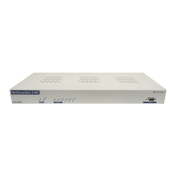
Expandable up to 160 discrete alarm inputs and 26 control outputs with the NetGuardian DX chassis. · The NetGuardian 216F is a 1 rack unit alarm remote that supports 16 discrete alarms that are "software reversible" to support both N/O and N/C alarm wiring, 8 analog inputs (4 general purpose, 1 for monitoring internal temperature, and 2 for monitoring battery feeds). -
Page 6: About This Manual
Shipping List Please make sure all of the following items are included with your NetGuardian 216F. If parts are missing, or if you ever need to order new parts, please refer to the part numbers listed and call DPS Telecom at 1-800-622-3314. - Page 7 14ft. Ethernet Cable 3/8" Ear Screws D-PR-932-10B-14 2-000-60375-05 Standard Rack Screws Metric Rack Screws 1-000-12500-06 2-000-80750-03 Pads Zip Ties 2-015-00030-00 1-012-00106-00...
-
Page 8: Optional Shipping Items - Available By Request
Optional Shipping Items - Available by Request Wire-Wrap Back Panel Temperature Sensor D-PA-00242-10A D-PR-998-10A-07 The NetGuardian 216F's Wire-Wrap back panel allows for wire- The NetGuardian 216F's external wrap connections for the discrete alarms, analog alarms, and temperature sensor cable for manual hook- control relays. -
Page 9: Optional Accessories
You can extend the capabilities of the NetGuardian through accessory units that provide greater discrete alarm capacity, remote audiovisual alarm notification, visual surveillance of remote sites, and other options. If you would like to order any of these accessories, or if you would like more information about them, call DPS Telecom at (800) 622-3314. - Page 10 Front Craft port and LEDs · Extended temp range, -22°F to 158°F (-30°C to 70°C) · · Firmware downloadable via LAN or SFP Fiber Interface · Web browser with multi-level security access SNMP–Traps to at least 2 masters natively · Special amphenol to Wire Wrap termination module ·...
- Page 11 Analog Input Range: (–94 to 94 VDC or 4 to 20 mA) Control Relays: Form A or Form C Maximum Voltage: 60 VDC/120 VAC Maximum Current: 3/4 Amp, AC/DC Discrete Alarms: Ping Alarms: Protocols: SNMPv1, v2c and v3 DCPx, DCPf, TRIP, SMTP, TAP Interfaces: 2 SFP Fiber Interfaces (1000Base-X) 7 RJ45 10/100/1000BaseT Ethernet ports...
-
Page 12: Hardware Installation
Hardware Installation Tools Needed To install the NetGuardian, you'll need the following tools: PC with Edit216F software Wire Strippers/Cutter Phillips No. 2 Screwdriver Punch Down Tool (if 66 blocks are used) Small Standard No. 2 Screwdriver Mounting The NetGuardian can be flush or rear-mounted The NetGuardian mounts in a 19"... -
Page 13: Power Connection
Power Connection Power connectors and fuses The NetGuardian has two screw terminal barrier plug power connectors, located on the left side of the back panel. (See Figure 6.3.1.) Before you connect a power supply to the NetGuardian, test the voltage of your power supply: Connect the black common lead of a voltmeter to the ground terminal of the battery, and connect the red ·... -
Page 14: Lan Connection
216F to the LAN, insert a standard RJ45 Ethernet cable into one of the Ethernet ports. From the NetGuardian 216F, the connection can be routed via Ethernet to a local subnet of up to 7 devices. Yost RS-232 RJ45 Connector Ethernet port pinout The pinout diagram for the Ethernet switch port is shown above. -
Page 15: Alarm And Control Relay Connections
Alarm and Control Relay Connections Alarm and control relay connectors The NetGuardian's discrete alarm inputs, control relay outputs, and analog alarm inputs are connected through the 50-pin connectors labeled "Discretes 1–16, Analogs 1-4, and Relays 1-2" on the back panel. 6.5.1 Alarm and Control Relay Connector Pinout Table Discretes 1–16 ALM 1... -
Page 16: Discretes 1-16 Connector Pinout Diagram
6.5.2 Discretes 1–16 Connector Pinout Diagram Pinout Diagram for Discretes 1-16 connector... -
Page 17: Optional 66 Block Connector
6.5.3 Optional 66 Block Connector Both of the 50-pin connectors on the back panel of the NetGuardian can be connected to the optional 25-pair 66 Block Connector (part number D-PR-966-10A-00). For 66 block pinout and color code information, see diagram below for Discretes 1–16. -
Page 18: Integrated Temperature And Battery Sensor
6.5.4 Integrated Temperature and Battery Sensor The integrated temperature and battery sensor monitors the ambient temperature and the NetGuardian's power feeds. This option is available only if it was ordered with your NetGuardian. The integrated temperature sensor measures a range of -22° F to 158° F (-30° C to 70° C) within an accuracy of ± 1°. Analog Function Location Channel Mapping... -
Page 19: Analog Dipswitches
6.5.5 Analog Dipswitches Dipswitch and layout The analogs are controlled by the dipswitches to the left of the Amphenol connector (located at the back of the unit). For milliamp sensor operation, turn the dipswitch on by placing it in the on position. For normal operation, place the dipswitch in the off position. -
Page 20: Data Port
6.5.6 Data Port The port can function as a DPC or ECU port. Data ports on the NetGuardian 216F Yost RS-232 RJ45 Connector Yost RS-485 RJ45 Connector 8 RTS (Request to Send) 8 TX- (Transmit -) 7 DTR (Data Term inal Ready) -
Page 21: Optional Wire-Wrap Back Panel
Integrated 10/100/1000BaseT Ethernet Switch NetGuardian integrated Ethernet switch The NetGuardian 216F comes equipped with an integrated 10/100/1000BaseT Ethernet switch, which provides seven regular Ethernet ports as shown above. The integrated Ethernet switch is powered by the same –48 VDC power as the NetGuardian, which provides more secure, more robust operation than switches that run off commercial power. -
Page 22: Front Panel Leds
Front Panel LEDs Front panel LEDs The NetGuardian's front panel LEDs indicate communication and alarm reporting status. LED status messages are described below. Status Description Link Solid Green Ethernet link detected Activity Blink Green Activity detected on Ethernet link No link detected Solid Green Link detected Blink Red... -
Page 23: Back Panel Leds
Back Panel LEDs Back panel LEDs for Power and Ethernet connections The back panel LEDs indicate the status of power and Ethernet connections. LED status messages are described below. Status Description Power not applied or polarity incorrect Pwr A Green Power applied Power Power not applied or polarity incorrent... -
Page 24: Connecting To The Netguardian
Connecting to the NetGuardian 10.1 ... via Craft Port NetGuardian Craft Port The simplest way to connect to the NetGuardian is over a physical cable connection between your PC's COM port and the NetGuardian's craft port. Note: You must be connected via craft port to use the TTY interface, but you don't have to be connected to a NetGuardian unit to use Edit216F. - Page 25 port and then assign it an IP address. Then you can complete the rest of the unit configuration over a remote LAN connection, if you want. For instructions, see section: "Connecting to the NetGuardian via Craft Port." If you DON'T have physical access to the NetGuardian, you can make a LAN connection to the unit by temporarily changing your PC's IP address and subnet mask to match the NetGuardian's factory default IP settings.
-
Page 26: Tty Interface
TTY Interface The TTY interface initial configuration screen The TTY interface is the NetGuardian's built-in provision controls for basic configuration of the NetGuardian. Configure the NetGuardian's Ethernet port settings, monitor the status of base and system alarms, operate control relays, view live ping targets , view debug or create proxy connections to other ports. -
Page 27: Unit Configuration
11.2 Unit Configuration 11.2.1 Ethernet Port Setup The NetGuardian must be assigned an IP address before you will be able to connect via LAN using a Telnet client or a Web browser. To connect via LAN, the minimum configuration requires setup of the IP address and subnet mask. Follow the instructions below to configure the NetGuardian's IP address, subnet mask, and default gateway for Ethernet connectivity. -
Page 28: Monitoring
11.3 Monitoring 11.3.1 Monitoring the NetGuardian Connect a PC running terminal emulation software to the craft port or connect via LAN using a Telnet client with emulation to port 2002 to reach the monitor menu selection. This section allows you to do full system monitoring of the NetGuardian including: all alarms, ping information, relays, analogs, and system status. -
Page 29: Monitoring Base Alarms
11.3.1.1 Monitoring Base Alarms View the status of the device connected to the discrete alarms from the M)onitor menu > A)larms option. Under Status, the word Alarm will appear if an alarm has been activated and Clear will appear if an alarm condition is not present. -
Page 30: Monitoring Ping Targets
11.3.1.2 Monitoring Ping Targets View the status of all your ping targets from the M)onitor menu > P)ing targets option. This screen displays the ping target ID, description, and IP address. Under Status the word Alarm will appear if an alarm has been activated and Clear will appear if an alarm condition is not present. -
Page 31: Monitoring Analogs
11.3.1.4 Monitoring Analogs View the current reading and the alarm status of your analog devices from the M)onitor menu > a(N)logs option. The value shown is a snapshot of the channels measurement, not a real-time reading. Refresh the readings by re- selecting the analogs option. -
Page 32: Monitoring System Alarms
11.3.1.5 Monitoring System Alarms View the status of the NetGuardian's system alarms from the M)onitor menu > S)ystem option. Under Status, the word Alarm will appear if an alarm has been activated and Clear will appear if an alarm condition is not present. See section: "System Alarms Display Map,"... -
Page 33: Monitoring Sfp Ports And Fiber Fault Detection
11.3.1.7 Monitoring SFP Ports and Fiber Fault Detection The NG216F can support 2 SPF connections. When using a compatible OpticalZonu SFP transceiver, the contents of their registers can be read and the fiber connection status and parameters are displayed in the TTY interface. The TTY interface displays information about the transceiver such as its Type, Vendor, Part No., and Wavelength, as well as diagnostic information on the connection status such as TX Power, RX Power, Voltage, Bias, and Temperature. - Page 34 Fiber Fault Detection and Micro OTDR If the SFP transceivers are Micro OTDR capable, the distance to the fiber fault will be displayed in this TTY interface when a fault is detected. It will take 15 - 30 seconds after power up for the micro OTDR to run. Once micro OTDR runs, the vendor name field will change from OpticalZonu,Corp to OZC followed by OTDR data: 1.
-
Page 35: Viewing Live Target Pings
11.3.2 Viewing Live Target Pings Choose P)ing to ping any of the NetGuardian's user defined IP addresses. Then enter the ID number (1-32) of the IP address or enter any IP address to ping. Continuously ping an IP address that has been defined in the NetGuardian's ping table 11.3.3 Event Logging Choose E)vent log to view the up to 100 events posted to the NetGuardian;... -
Page 36: Backing Up Netguardian Configuration Data Via Ftp
11.3.4 Backing Up NetGuardian Configuration Data via FTP From the Start menu on your PC, select RUN. Type "ftp" followed by the IP address of the NetGuardian you are backing up (example: ftp 126.10.120.199). After the connection is made press Enter. Enter the password of the NetGuardian (default password is dpstelecom), then press Enter. -
Page 37: Debug Input And Filter Options
11.3.5 Debug Input and Filter Options Debug Input Options Exit Debug Show task status Show DUART information Show network routing table Clear debug enable bitmap. Turn all debug filters OFF Display Options Debug Filter Options: Alarm toggle switch. Shows posting of alarm data Analog toggle switch. -
Page 38: Reference Section
Reference Section 12.1 Display Mapping Port Address Display Description Clear Discrete Alarms 1-16 8001-8016 9001-9016 Ping Table 8065-8096 9065-9096 Analog Channel 1** 8129-8132 9129-9132 Analog Channel 2** 8193-8196 9193-9196 Analog Channel 3** 8257-8260 9257-9260 Analog Channel 4** 8321-8324 9321-9324 Analog Channel 5–Pow er Feed A** 8385-8388 9385-9388 Analog Channel 6–Pow er Feed B**... - Page 39 SNMP Trap #s Points Description Clear Undefined** 8653 9653 Undefined** 8654 9654 Undefined** 8655 9655 Undefined** 8656 9656 Timed Tick 8657 9657 Exp. Module Callout 8658 9658 Netw ork Time Server 8659 9659 Accumulation Event 8660 9660 Duplicate IP Address 8661 9661 Undefined**...
- Page 40 SNMP Trap #s Points Description Clear Data 8 RcvQ full 8695 9695 NetGuardian DX 1 fail 8696 9696 NetGuardian DX 2 fail 8697 9697 NetGuardian DX 3 fail 8698 9698 GLD/BSU 1 Fail 8699 9699 GLD/BSU 2 Fail 8700 9700 GLD/BSU 3 Fail 8701 9701...
-
Page 41: System Alarms Display Map
12.1.1 System Alarms Display Map Display Points Alarm Point Description Solution Toggles state at constant rate as configured by the Timed Tick timer variable. To turn the feature off, set the Timed Tick timer Timed Tick Useful in testing integrity of SNMP trap to 0. - Page 42 Display Points Alarm Point Description Solution Serial 1 RcvQ full Serial 2 RcvQ full Serial 3 RcvQ full Serial port 1 (or appropriate serial port Serial 4 RcvQ full Check proxy connection. The serial port data number) receiver filled w ith 8 K of data (4 K may not be getting collected as expected.
-
Page 43: Snmp Manager Functions
APntDesc (.5)* Display (.3) AState (.6) Point (.4) * For specific alarm points, see Table Action (.5) The NetGuardian 216F OID has changed from 1.3.6.1.4.1.2682.1.4 to 1.3.6.1.4.1.2682.1.2 Hot Tip! Updated MIB files are available on the Resource CD or upon request. - Page 44 Description Port Address Display Points Disp 1 Discrete Alarms 1-32 Undefined** 33-64 Disp 2 Ping Targets 1-32 Undefined** 33-64 Disp 3 Analog 1 Undefined** 5-64 Disp 4 Analog 2 Undefined** 5-64 Disp 5 Analog 3 Undefined** 5-64 Disp 6 Analog 4 Undefined** 5-64 Disp 7...
- Page 45 Description Port Address Display Points NGDdx 1-3 fail 56-58 GLD/BSU 1-3 fail 59-61 CHAN timeout CRFT timeout Event Que Full Alarm point descriptions (continued) * "No data" indicates that the alarm point is defined but there is no description entered. ** "Undefined"...
-
Page 46: Snmp Granular Trap Packets
Public Request Trap Request 1.3.6.1.4.1.2682.1.2 Enterprise 126.10.230.181 Agent address Enterprise Specific Generic Trap 8001 Specific Trap 617077 Time stamp 1.3.7.1.2.1.1.1.0 Object NetGuardian 216F v1.0B Value 1.3.6.1.2.1.1.6.0 Object 1-800-622-3314 Value 1.3.6.1.4.1.2682.1.2.4.1.0 Object 01-02-1995 05:08:27.760 Value 1.3.6.1.4.1.2682.1.2.5.1.1.99.1.1.1 Object Value 1.3.6.1.4.1.2682.1.2.5.1.4.99.1.1.1 Object Value 1.3.6.1.4.1.2682.1.2.5.1.3.99.1.1.1... -
Page 47: Ascii Conversion
12.4 ASCII Conversion The information contained in Table 12.4.A is a list of ASCII symbols and their meanings. Refer to the bulleted list below to interpret the ASCII data transmitted or received through the data port. Port transmit and receive activity can be viewed from the Web browser interface. -
Page 48: Frequently Asked Questions
Frequently Asked Questions Here are answers to some common questions from NetGuardian users. The latest FAQs can be found on the NetGuardian support web page, http://www.dpstele.com If you have a question about the NetGuardian, please call us at (559) 454-1600 or e-mail us at support@dpstele.com 13.1 General FAQs... - Page 49 Telnet is connected through the 10BaseT switch. Make sure you're connected to one of the switch's 7 connectors. Q. I just changed the port settings for one of my data ports, but the changes did not seem to take effect even after I wrote the NVRAM.
-
Page 50: Snmp Faqs
The T/MonXM variables are included in the distributed MIB only to provide SNMP managers with a single MIB for all DPS Telecom products. Q. How many traps are triggered when a single point is set or cleared? The MIB defines traps like "major alarm set/cleared,"... - Page 51 Q. How can I associate descriptive information with a point for the RTU granular traps? A. The NetGuardian alarm point descriptions are individually defined using the Web Browser, TTY, or Edit216F configuration interfaces. Q. My SNMP traps aren't getting through. What should I try? A.
-
Page 52: Technical Support
3. Have access to troubled equipment. Please be at or near your equipment when you call DPS Telecom Technical Support. This will help us solve your problem more efficiently. 4. Call during Customer Support hours. -
Page 53: Rma Policy
DPS Telecom which arise out of or are related to the non-fulfillment of any covenant or obligation of End User in connection with this Agreement. - Page 56 33 debug input, 33 dimensions, 5 discrete alarm inputs, capacity, 5 display mapping, 34 Edit216F, connecting to the NetGuardian 216F, 20, 20 Ethernet port, 10 event logging, 31 firmware updates, 1 frequently asked questions (FAQs), 44 general, 44 SNMP, 46...
- Page 57 5 LAN, 1, 10 LAN connections, making a LAN connection, 20 MIB object identifiers, 39 NetGuardian 216F, accessories, 5 accessory part numbers, 5 configuration interfaces, 2 connecting via craft port, 20 connecting via LAN, 20 MIB, 46 provisioning, 2...
- Page 58 technical support, 44, 48 e-mail address, 44 phone number, 44, 48 web page, 48 Telnet, 44 temperature, external temperature sensor, 14 integrated temperature and battery sensor, 1, 14 specifications, 5 TTY, Analogs, 27 Base Alarms, 25 Controls, 26 Data Port Activity, 28 Ethernet Port, 23 menu keys, 22 Monitoring, 24...
- Page 60 “D ependable, Powerful Solutions that allow users to monitor larger, more complicated networks with a smaller, less trained staff” “Yo u r Part n ers i n Net w o rk Al arm Man ag emen t ” www.dpstelecom.com 4955 E Yale • Fresno, CA 93727 559-454-1600 •...
Need help?
Do you have a question about the NetGuardian 216F and is the answer not in the manual?
Questions and answers