
Related Manuals for DPS Telecom NetGuardian 16 G2


Summary of Contents for DPS Telecom NetGuardian 16 G2
- Page 1 NetGuardian 16 G2 and Voice 16 G2 USER MANUAL D-PK-216G2 D-PK-C16V2 Visit our website at www.dpstelecom.com for the latest PDF manual and FAQs. January 2, 2014 D-UM-216V2 / C16V2 Firmware Version 1.0A...
- Page 2 Notice The material in this manual is for information purposes and is subject to change without notice. DPS Telecom shall not be liable for errors contained herein or consequential damages in connection with the furnishing, performance, or use of this...
-
Page 3: Table Of Contents
Contents Visit our w ebsite at w w w .dpstelecom .com for the latest PDF m anual and FAQs NetGuardian 16 G2 / Voice 16 G2 Overview Specifications Shipping List Optional Shipping Items - Available by Request Optional NetGuardian Accessories... - Page 4 How to Send TRIP Notifications (Voice 16 G2 Only) Provisioning Menu Field Descriptions 11.1 System 11.2 User Profiles 11.3 Ethernet 11.4 Serial Ports (NetGuardian 16 G2 Only) 11.5 SNMP 11.6 Phone List (Voice 16 G2 Only) 11.7 Notifications 11.7.1 Notification Settings 11.7.2...
- Page 5 Technical Support End User License Agreement...
-
Page 7: Netguardian 16 G2 / Voice 16 G2 Overview
Effective, easy-to-install, light-capacity alarm monitoring The NetGuardian 16 G2 is a compact, LAN-based, light-capacity remote telemetry unit. This unit is designed for easy installation at small and medium remote sites, making it cost-effective to deploy alarm monitoring throughout your entire telecom network. The NetGuardian Voice 16 G2 features the monitoring capacity plus voice dialing capabilities for flexible notifications. -
Page 8: Specifications
1 RJ45 10/100BaseT full-duplex Ethernet port 1 USB front-panel craft port 1 RJ11 connector for D-Wire sensor network 1 Serial port: RS232, RS485, or 202 (NetGuardian 16 G2 only) 1 Telco jack (Voice 16 G2 only) Visual Interface: 5 Front Panel LEDs... -
Page 9: Shipping List
Shipping List Please make sure all of the following items are included with your NetGuardian 16 G2 or NetGuardian Voice 16 G2. If parts are missing, or if you ever need to order new parts, please refer to the part numbers listed and call DPS Telecom at 1-800-622-3314. -
Page 10: Optional Shipping Items - Available By Request
Three 3/4-Amp GMT Fuses Two Standard Rack Screws 2-741-00750-00 1-000-12500-06 3/8" Ear Screws Four Metric Rack Screws 2-000-60375-05 2-000-80750-03 Telephone Cable 6 ft (Voice 16 G2 Only) D-PR-045-10A-01 Optional Shipping Items - Available by Request D-Wire Temperature Sensor D-Wire Temperature/Humidity Sensor D-PK-DSNSR-12001.00001 D-PK-DSNSR-12002.00002 Optional NetGuardian Accessories... -
Page 11: Installation
Installation Tools Needed To install the NetGuardian, you'll need the following tools: Phillips No. 2 Screwdriver Small Standard No. 2 Screwdriver PC with terminal emulator, such as HyperTerminal Mounting NetGuardian can be flush or rear-mounted The NetGuardian mounts in a 19" or 23" rack and can be mounted in the flush-mount or rear mount locations, as shown in. -
Page 12: Netguardian Back Panel
NetGuardian Back Panel NetGuardian 16 G2 / Voice 16 G2 back panel connections Power Connection The NetGuardian is powered by two barrier plug power connectors. Lock ing RIA power inputs To connect the NetGuardian to a power supply: 1. Use the grounding lug to connect the unit to earth ground. The grounding lug is next to the symbol 2. -
Page 13: Serial Connection (Netguardian 16 G2 Only)
Serial Connection (NetGuardian 16 G2 Only) The NetGuardian 16 G2 has 3 build options for it's serial / dialup port. You can order your port as a Yost RS-232, RS-485, 202 modem, or 4-wire 202 RJ45. The serial port is located on the back panel, where it is labeled "Primary."... -
Page 14: Telco Connection (Voice 16 G2 Only)
Telco Connection (Voice 16 G2 Only) The NetGuardian Voice 16 G2 features an RJ11 Telco port on the back of the unit. This port is used for dial-up notification via your cell phone and alphanumeric pager. Telco Port Pinout 50-Pin Alarm and Control Relay Connector The primary connectors for discrete alarms, analog alarms and control relays are the 50-pin Amphenol connector on the NetGuardian's back panel. - Page 15 Amphenol connector pinout.
-
Page 16: Optional 66 Block Connector
Optional 66 Block Connector The unit is also available with an optional 66 Block Connector for connecting discrete alarms, analog alarms and control relays. Pinout and wire color coding are shown. Optional 66 block connector pinout... - Page 17 Optional 66 block connector pinout for controls...
-
Page 18: Discrete Alarms
Discrete Alarms Dry Contact Contact to Ground NetGuardian case NetGuardian case Alarm Alarm – Batt. – Batt. Note: Make sure that grounds have a common reference - this is usually done by tying grounds together. Discrete alarm points can connect as a dry contact or a contact to ground This device features 16 discrete alarm inputs - also called digital inputs or contact closures. -
Page 19: Analog Alarms
Analog Alarms The NetGuardian's analog alarm inputs measure continuous ranges of voltage or current. Analog alarms are typically used to monitor battery voltage, charging current, temperature, humidity, wind speed, or other continuously changing conditions. The measurement range of the analog channels is -90 to +90 VDC or 4 to 20 mA. To configure the analogs for current sensing (4 - 20mA) please review the next section for jumper position. -
Page 20: Analog Step Sizes
Jumper installed for current Current Analog 4 to 20 mA Jumper Analog 250 Ohm Channel Current Source Shunt Input ANA 1 Transducer ANA 2 Jumper removed for voltag e ANA 3 Voltage ANA 4 Unjumpered/Open Position: Analog Jumpered/Closed Position: Voltage Source Channel Voltage Operation (default) Current Operation... - Page 21 Maximum Cable Lengths Note: Some sensors may consume 2 analog channels (the combined temp/humidity sensor, D-PK-DSNSR-12002, for example). Connecting D-Wire Sensors Warning: Be sure to only use a straight-through RJ-11 cable (part #D-PR-901-10A-XX, pinout below) to connect any digital sensor port on the NetGuardian to the In jack on a D-Wire sensor. Chain additional sensors to the D- Wire sensor (using the same straight-through cables) from the Out jack on the previous sensor to the In jack on the next (i.e.
-
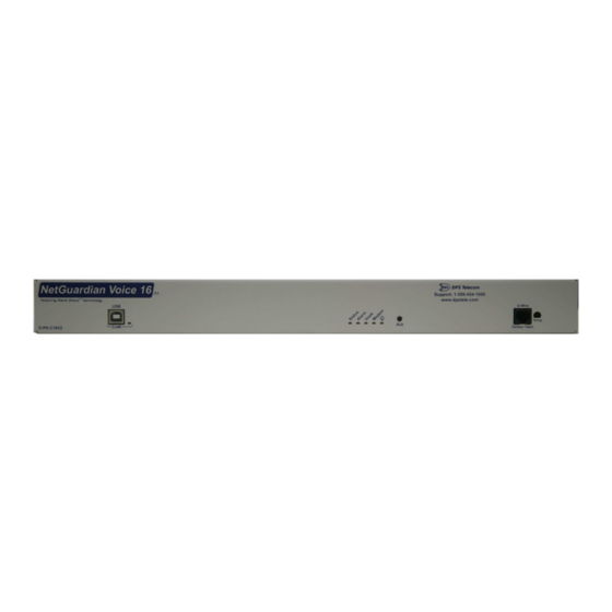
Page 22: Netguardian Front Panel
NetGuardian Front Panel NetGuardian 16 G2 / Voice 16 G2 Front panel connections Status Description Flashing Red New alarm Alarm Solid Red Standing alarm acknowledged Error Flashing Red System error Flashing Green Data transmitted on PRI Serial Primary Flashing Red... -
Page 23: Quick Start: How To Connect To The Netguardian
Quick Start: How to Connect to the NetGuardian Most NetGuardian users find it easiest to give the unit an IP address, subnet and gateway through the front craft port (TTY interface) to start. Once these settings are saved and you reboot the unit, you can access it over LAN to do the rest of your databasing via the Web Browser interface. - Page 24 Note: The following images display the setup process done in Windows XP. The following steps will occur the first time any DPS USB equipment is used on this PC. If you've used a different DPS USB device before and have installed the DPS USB drivers, then skip to Step 9. When you first connect the NetGuardian to your PC via USB, a "Found New Hardware"...
- Page 25 6. Click "Browse" 7. Select the "Driver" folder of your NetGuardian Resource Disc Disc (CD) and click "OK" The following message will confirm installation of a new "USB Communications Port" 8. Click "Finish" to close the Wizard. Now that the driver has been installed, a new COM port is being emulated on your PC. Before using hyperterminal, you must confirm the identity of that new COM port (COM1, COM2, COM3...) in the Windows Device Manager.
- Page 26 9. Right-click the "My Computer" icon on your desktop, then click "Manage" 10. Click "Device Manager" in the left pane.
- Page 27 11. Expand the "Ports (COM & LPT)" section in the right pane. Look for "USB Communications Port (COMx)". Note the number of the COM port ("COM3" in the example above). Now that you know which COM port to use, it's time to launch HyperTerminal (or other terminal software): 12.
- Page 28 • Stop bits: 1 PC and make sure you are using the cable provided. • Flow control: None Additional cables can be ordered from DPS Telecom. Once connected, you will see a blank, white HyperTerminal screen. Press Enter to activate the configuration menu.
- Page 29 Now you're ready to do the rest of your configuration via LAN. Plug the NetGuardian into your LAN and see the "Logging On to the NetGuardian" section to continue databasing using the Web Browser..via LAN Connection through Ethernet port To connect to the NetGuardian via LAN, all you need is the unit's IP address (Default IP address is 192.168.1.100).
-
Page 30: Tty Interface
TTY Interface The TTY interface is the NetGuardian's built-in interface for basic configuration. From the TTY interface, you can: Edit the IPA, subnet, and gateway Set DCP info for T/Mon polling Configure primary port Ping other devices on the network Set unit back to factory defaults Debug and troubleshoot For more advanced configuration tools, please use the Web Browser Interface. -
Page 31: Configure Serial Port Via Tty (Netguardian G2 16 Only)
Configure Serial Port via TTY (NetGuardian G2 16 Only) Serial port configuration 1. To enter configuration setting for the Serial Port, login to the TTY interface and press C)onfig > pr(I)maryPort. 2. Press the hot keys to toggle through the following options. (* Indicates default settings:) NOTE: Default settings may not reflect the primary interface that shipped in the unit. -
Page 32: Tune 202 Modem (Netguardian 16 G2 Only)
Tune 202 Modem (NetGuardian 16 G2 Only) Tuning the 202 modem on a NetGuardian 16 G2 can only be done from the TTY interface (using either HyperTerminal through the front craft port or by telnet over LAN on port 2002). -
Page 33: Netguardian Web Browser
NetGuardian Web Browser The NetGuardian features a built-in Web Browser Interface that allows you to manage alarms and configure the unit through the Internet or your Intranet. You can quickly set up alarm point descriptions, view alarm status, issue controls, configure paging information, and more. -
Page 34: Changing The Default Password
9.1.1 Changing the Default Password The password can be configured from the Provisioning > User Profiles screen. The minimum password length is four characters; however, DPS recommends setting the minimum password length to at least five characters. Use the following steps to change the logon password: 1. -
Page 35: Using Radius Authentication (Available As Of Firmware 5.01)
Using RADIUS Authentication (Available as of Firmware 5.01) RADIUS (Remote Authentication Dial In User Service) is an industry-standard way to manage logins to many different types of equipment in one central location. The NetGuardian Voice 16 G2 connects to your central RADIUS server. -
Page 36: Netguardian - Quick Turn Up
NetGuardian - Quick Turn Up The next 4 sections of this manual will walk you through some of the most common tasks for using the NetGuardian. You will learn how to send email notifications, and send SNMP traps to your alarm master - all using the Web browser. - Page 37 4. At the Schedule screen, you'll select the exact days/times you want to receive email notifications. You can set 2 schedules per notification. For example, you may want to receive notifications at certain times during the week, and at different hours on the weekend. Use the check boxes to select the days of the week, and select the time from the drop down menus.
-
Page 38: How To Send Snmp Traps
10.2 How to Send SNMP Traps 1. Click on the SNMP button in the Provisioning menu. Enter the SNMP GET and SNMP SET community strings for your network, then click Save. The typical SNMP SET and GET community strings for network devices is "public". - Page 39 4. At the SNMP Notification screen, you'll enter your network's SNMP settings. Enter the IP address of your SNMP Trap Server. Enter the Trap Port Number (usually 162) and the Trap Community password. Click Save and Next. 5. At the Schedule screen, you'll select the exact days/times you want to receive SNMP notifications. You can set 2 schedules per notification.
-
Page 40: How To Send Call (Voice) Notifications (Voice 16 G2 Only)
10.3 How to Send Call (Voice) Notifications (Voice 16 G2 Only) The following instructions will guide you through the process of setting up the unit to call your phone when alarms are triggered. Using your custom call list, the NetGuardian Voice 16 G2 will begin the calling tree to notify the correct personnel, according to their schedules. - Page 41 5. At the Schedule screen, you'll select the exact days/times you want to receive notifications. You can set 2 schedules per notification. For example, you may want to send after hours or at certain times during the week, and at different hours on the weekend. Use the check boxes to select the days of the week, and select the time from the drop down menus.
-
Page 42: How To Send Trip Notifications (Voice 16 G2 Only)
10.4 How to Send TRIP Notifications (Voice 16 G2 Only) 1. Click on the Notifications button in the Provisioning menu. You can setup as many as 8 different notifications. Begin the setup "wizard" by clicking on Edit for a notification number. In this example, we'll setup Notification 8 to send an voice alert. -
Page 43: Provisioning Menu Field Descriptions
Provisioning Menu Field Descriptions NetGuardian configuration is performed from the Provisioning menus, the menu options in green on the left-side of the web interface. The following pages provide a brief description of the options available in each menu. Saving Configuration Changes to the NetGuardian: At the bottom of each screen you access from the Provisioning Menu, you will see a Save button. -
Page 44: System
11.1 System From the Provisioning > System menu, you will configure and edit the global system, call, T/Mon and control settings for the NetGuardian. The Provisioning > System menu... - Page 45 Global System Settings Name A name for this NetGuardian unit. {Optional field) Location The location of this NetGuardian unit. {Optional field) Contact telephone number for the person responsible for this NetGuardian unit. Contact {Optional field) DTMF Pass Code Used to login to the unit via telephone to hear alarm notifications. Only number entries (Voice 16 G2 Only) are valid.
-
Page 46: User Profiles
11.2 User Profiles Clicking User Profiles gives you access to modify the default username and password, and to edit the administrator profile and create up to 9 additional unique user profiles, each with different access rights to the NetGuardian's web interface. - Page 47 To create or edit any of the 10 user profiles (including the default), click the Edit button. From there, you can change all configurable settings for a user profile. User Profile Suspend this Profile If this box is checked, the profile will not be able to access the NetGuardian. Username Enter a username or a user description Password...
-
Page 48: Ethernet
11.3 Ethernet The Edit > Ethernet menu allows you to define and configure Ethernet settings. The Provisioning > Ethernet menu Ethernet Settings MAC Address Hardware address of the NetGuardian. (Not editable - For reference only.) Used only for web browsing. Example: If you don't want to remember this NetGuardian's IP address, you can type in a name is this field, such as NG16. -
Page 49: Serial Ports (Netguardian 16 G2 Only)
11.4 Serial Ports (NetGuardian 16 G2 Only) The Provisioning > Serial Port menu allows you to change settings depending on the port type of your NetGuardian. From this menu, you can select a mode of operation and enable reach-through serial port functionality. -
Page 50: Snmp
11.5 SNMP The Provisioning > SNMP menu allows you to define and configure the SNMP settings. SNMP Menu Global Settings Get Community Community name for SNMP requests. Set Community Community name for SNMP SET requests. This field defines how the NetGuardian unit may be accessed via SNMP. This can be set to the following: Read and Write Access Disabled- Restricts all access to unit via SNMP... - Page 51 The Provisioning > Phone List menu...
-
Page 52: Notifications
11.7 Notifications From the initial Provisioning > Notifications menu, you will see which of the 8 notifications are enabled, their server, and schedule. Click on the Edit link for one of the notifications to begin configuration. Once you've chosen which notification you want to setup, check the Enable Notification to turn it "on." Then choose a notification method, either email, SNMP, voice call, or TRIP Dialup (T/Mon). - Page 53 you will have to enter the relevant authentication information the fields below.
- Page 54 SNMP Notification Fields Editing SNMP notification settings SNMP Notification SNMP Trap Server IP The SNMP trap manager's IP address. The SNMP port (UDP port) set by the SNMP trap manager to receive Trap Port No. traps, usually set to 162. Trap Community Community name for SNMP TRAP requests.
-
Page 55: 11.7.2 Schedule
TRIP Dialup (T/Mon) Notification Fields (Voice 16 G2 only) Editing Call notification settings Call Notification T/Mon Phone Number Enter the phone number for your T/Mon unit Only dial if DCP poller Check this box if you want the Netguardian to only dial if the DCP poller inactive alarm is set inactive alarm is set Note: T/Mon will need to have a "^"... -
Page 56: Alarms
11.8 Alarms Discrete alarms are configured from the Provisioning > Alarms menu. Descriptions for the alarm points, polarity (normal or reversed) and notification type(s) are defined from this menu. You also have the option to use Basic or Advanced configuration methods, explained in this section. The Provisioning >... -
Page 57: Controls
11.9 Controls The NetGuardian's 2-18 control relays can be configured in the Provisioning > Controls menu. You can enter your own description for these relays and designate them to a notification device(s). The Provisioning > Controls screen Basic Controls Configuration ID number for the control relay. -
Page 58: Analogs
11.10 Analogs The NetGuardian can have up to 6 analog channels. The 5th and 6th channels are dedicated to monitoring the power input (channel is not used if build option was not selected). These channels support the entire range of power inputs that the NetGuardian can support. - Page 59 Basic Analog Configuration Analog ID number. Enab Check this box to enable the analog. Description User-definable description for the analog channel. Check which notification device(s), 1 through 8, you want to send alarm notifications Notification Devices for that alarm point. Advanced Analog Configuration (Details>>) The amount of time, in minutes (min) or seconds (s), between each log of each Record Freq...
-
Page 60: Sensors
11.11 Sensors The NetGuardian supports up to 16 daisy-chained D-Wire sensors via its D-Wire input. Sensors connected to the NetGuardian will appear on the NetGuardian's web interface. The background color of the ROM field informs the user of the sensor's configuration state. Also the NetGuardian's first D-Wire sensor used to monitor the internal temperature. - Page 61 Basic Sensor Configuration Sensor ID number. The ID number found on the sticker of the temperature sensor node. Your NetGuardian will automatically detect the sensor ID when you plug a sensor into the unit. The color of the sensor ID field will tell you the status of the connected sensor. Green - The sensor is connected and properly configured.
-
Page 62: Ping Targets
11.12 Ping Targets The Provisioning > Ping Targets menu allows you to configure the Description, IP Address, and Notification Devices for each of your 32 ping targets. The Provisioning > Ping Targets menu Provisioning Ping Targets ID number for the ping target. Enab Check this box to enable the ping target. -
Page 63: System Alarms
11.13 System Alarms See "Display Mapping" in the Reference Section for a complete description of system alarms. The Provisioning > System Alarms menu Editing System Alarms Pnt (Point) The system alarm point number Description Non-editable description for this System (housekeeping) Alarm. Silence Check this box to choose to silence this alarm. -
Page 64: Timers
11.14 Timers The Timers are user-definable, and allow you to choose the intervals between automatic refreshing of the unit's web browser interface. Enter the amount of time, in seconds (sec) or minutes (m), in the value field and click Save. The Provisioning >... -
Page 65: Date And Time
11.15 Date and Time The Provisioning > Date and Time menu Unit Time Date Set today's date. Time Set the current time. Automatic Time Adjustment (NTP) Enable NTP Check this box to enable Network Time Protocol. Enter the NTP server's IP address or host name, then click Sync. NTP Server Address or Host Name Example: us.pool.ntp.org. -
Page 66: Monitoring Via The Web Browser
Monitoring via the Web Browser 12.1 Alarms This selection provides the status of the base alarms by indicating if an alarm has been triggered. Under the State column, the status will appear in red if an alarm has been activated. The status will be displayed in green when the alarm condition is not present. -
Page 67: Controls
2) The maximum time value is 18 hours. Once 18 hours is reached, the timer will stop counting. 3) The timer will survive a soft reboot (a reboot from the web interface). 4) The timer will not survive a hard reboot (losing power, disconnection, etc). The timer will be restored to its previously saved value. - Page 68 MOM - Momentarily latch the relay, then automatically release the relay. The duration of the latch is defined in the Provisioning > Controls menu.
-
Page 69: Analogs
12.3 Analogs The Monitor > Analogs screen provides a description of each analog channel, the current reading, the units being read, and alarm conditions (major under, minor under, major over, minor over) according to your temperature settings. If configured under Provisioning > Analogs, your analog values will be displayed as a graphical gauge. Selecting Table View will display a non-graphical interface of your values. -
Page 70: Sensors
12.4 Sensors This selection provides the status of the system's analog channels by indicating if an alarm has been triggered. The Monitor > Sensors screen provides a description of each analog channel, the current reading, the units being read, and alarm conditions (major under, minor under, major over, minor over) according to your temperature settings. If configured under Provisioning >... -
Page 71: Ping Targets
12.5 Ping Targets Ping Targets can be viewed by going to Monitor > Ping Targets. Here you can view the state (either Clear or Alarm) for each of your configured Ping Targets. Up to 32 ping targets may be configured. View the status of Ping Targets from the Monitor >... -
Page 72: Graph
12.7 Graph The Graph section of the monitor menu lets you build a graph of past sensor measurements, which gives you a visual indication of data over time and points out trending values. To create your Graph, specify the Channel (Analogs 1-6 or Sensors 1-16), Group Interval (1-120 minutes, hours, days, or weeks), the Group Function (Average, Min, Max), and Start &... - Page 73 Your graph will appear on the next screen. This graph is Adobe Flash-based and allows you to mouse over the lines to quickly view measurements (date, time, and value) within their context of the overall graphing trend. Below the graph is a full textual list of all indexed points with their dates and values. Specify your parameter values and build an interactive graph based on the alarm point history.
-
Page 74: Device Access Descriptions
Device Access Descriptions The Device Access options, listed in pink on the left side of the web interface, provide options for generating reports, updating the NetGuardian's firmware, and rebooting the unit. Click any of the options under Device Access to perform the desired action. The control menu is located in the bottom left of the web interface Device Access Option Description... -
Page 75: Firmware Upgrade
Firmware Upgrade To access the Firmware Load screen, click on the Provisioning > System menu. At the bottom of this screen, click the Restore Configuration link located in the System Controls section. To upload firmware, click on Upload on the top right corner of the web interface At the Firmware Load screen, simply browse for the firmware update you've downloaded from www.dpstele.com and click Load. -
Page 76: Front And Back Panel Led
Front and Back Panel LED Front panel LEDs Status Description Flashing Red New alarm Alarm Solid Red Standing alarm acknowledged Error (NG Flashing Red System error 16 Only) Primary Flashing Green Data transmitted on PRI Serial (NG 16 Flashing Red Data recieved on PRI Serial Only) Hook... -
Page 77: Reference Section
Reference Section 16.1 Display Mapping & System Alarms Description Port Address Point Discrete Alarms 1-16 Default Configuration DCP Poller Inactive SNMP Community Error Notification 1 Failed Notification 2 Failed Notification 3 Failed Notification 4 Failed Notification 5 Failed Display 1 Notification 6 Failed Notification 7 Failed Notification 8 Failed... - Page 78 Power A Major Over Control 9-16 Value 17-32 Power B Minor Under Power B Minor Over Power B Major Under Power B Major Over Control 41-48 Value 49-64 Digital sensor 1 Minor Under Digital sensor 1 Minor Over Digital sensor 1 Major Under Digital sensor 1 Major Over Digital sensor 1 Sensor not detected Control...
- Page 79 Display Description Port Address Point Digital sensor 3 Minor Under Digital sensor 3 Minor Over Digital sensor 3 Major Under Digital sensor 3 Major Over Digital sensor 3 Sensor not detected Control 9-16 Value 17-32 Display 7 Digital sensor 4 Minor Under Digital sensor 4 Minor Over Digital sensor 4 Major Under Digital sensor 4 Major Over...
- Page 80 Display Description Port Address Point Digital sensor 9 Minor Under Digital sensor 9 Minor Over Digital sensor 9 Major Under Digital sensor 9 Major Over Digital sensor 9 Sensor not detected Control 9-16 Value 17-32 Display 10 Digital sensor 10 Minor Under Digital sensor 10 Minor Over Digital sensor 10 Major Under Digital sensor 10 Major Over...
- Page 81 Display Description Port Address Point Digital sensor 15 Minor Under Digital sensor 15 Minor Over Digital sensor 1 Major Under Digital sensor 15 Major Over Digital sensor 15 Sensor not detected Control 9-16 Value 17-32 Display 13 Digital sensor 16 Minor Under Digital sensor 16 Minor Over Digital sensor 16 Major Under Digital sensor 16 Major Over...
- Page 82 Display Points Alarm Point Description Solution The internal NVRAM may be damaged. Login to the NetGuardian's web Default The unit is using default configuration browser and configure the unit. Power configuration settings. cycle to see is the alarm clears. The NetGuardian is configured to listen Check if unit can ping T/Mon or disable DCP poller for DCP polls but has not received a...
-
Page 83: Voice Notification Flow Chart
16.2 Voice Notification Flow Chart Press 1 Press 2 Press 3 Press 4 Press 5 Press 6 Press 7 Press * Press # Main Menu List Events Acknowledge List Standing Go to Operate Go to More all Events Alarms Relays Options More Options Record... -
Page 84: Snmp Granular Trap Packets
Tbl. B1 (O.)_OV_Traps Tbl. B2 (.1) Identity points Tbl. B3 (.2) DisplayGrid points points Ident _OV_vTraps (1.3.6.1.4.1.2682.1.2.1) DisplayEntry (1.3.6.1.4.1.2682.1.2.0) (1.3.6.1.4.1.2682.1.2.2.1) Manufacturer (.1) PointSet (.20) Port (.1) Model (.2) PointClr (.21) Address (.2) Firmware Version (.3) SumPSet (.101) Display (.3) DateTime (.4) SumPClr (.102) DispDesc (.4)* ResyncReq (.5)*... - Page 85 SNMP Header Description Version Public Request Trap Request 1.3.6.1.4.1.2682.1.4 Enterprise 126.10.230.181 Agent address Enterprise Specific Generic Trap 8001 Specific Trap 617077 Time stamp 1.3.7.1.2.1.1.1.0 Object NetGuardian v1.0K Value 1.3.6.1.2.1.1.6.0 Object 1-800-622-3314 Value 1.3.6.1.4.1.2682.1.4.4.1.0 Object 01-02-1995 05:08:27.760 Value 1.3.6.1.4.1.2682.1.4.5.1.1.99.1.1.1 Object Value 1.3.6.1.4.1.2682.1.4.5.1.2.99.1.1.1 Object Value...
-
Page 86: Frequently Asked Questions
Frequently Asked Questions Here are answers to some common questions from NetGuardian users. The latest FAQs can be found on the NetGuardian support web page, http://www.dpstele.com. If you have a question about the NetGuardian, please call us at (559) 454-1600 or e-mail us at support@dpstele. -
Page 87: Snmp Faqs
A. The NetGuardian begins sending traps as soon as the SNMP managers are defined. The NetGuardian MIB can be found on the DPS Telecom website. The MIB should be compiled on your SNMP manager. (Note: MIB versions may change in the future.) The unit supports 2 SNMP managers, which are configured by entering its IP address in the Trap Address field of Ethernet Port Setup. - Page 88 3. Have access to troubled equipment. Please be at or near your equipment when you call DPS Telecom Technical Support. This will help us solve your problem more efficiently. 4. Call during Customer Support hours.
- Page 89 DPS Telecom which arise out of or are related to the non-fulfillment of any covenant or obligation of End User in connection with this Agreement.
- Page 93 Warranty DPS Telecom warrants, to the original purchaser only, that its products a) substantially conform to DPS' published specifications and b) are substantially free from defects in material and workmanship. This warranty expires two years from the date of product delivery with respect to hardware and ninety days from the date of product delivery with respect to software.
- Page 94 Free Tech Support is Only a Click Away Need help with your alarm monitoring? DPS Information Services are ready to serve you … in your email or over the Web! www.DpsTelecom.com Free Tech Support in Your Email: The Protocol Alarm Monitoring Ezine The Protocol Alarm Monitoring Ezine is your free email tech support alert, delivered directly to your in-box every two weeks.
Need help?
Do you have a question about the NetGuardian 16 G2 and is the answer not in the manual?
Questions and answers