
Related Manuals for DPS Telecom NetGuardian BSM


Summary of Contents for DPS Telecom NetGuardian BSM
- Page 1 NetGuardian BSM and BSM-G2 USER MANUAL D-PK-NGBSM Visit our website at www.dpstelecom.com for the latest PDF manual and FAQs. July 19, 2019 D-UM-NGBSM Firmware Version 2.0A...
- Page 2 © 2019 DPS Telecom Notice The material in this manual is for information purposes and is subject to change without notice. DPS Telecom shall not be liable for errors contained herein or consequential damages in connection with the furnishing, performance, or...
-
Page 3: Table Of Contents
Power Connection Configuration NetGuardian BSM Front and Back Panel NetGuardian BSM G2 Front and Back Panel Data Ports Quick Start: How to Connect to the NetGuardian BSM ...via Craft Port (using TTY Interface) ...via LAN TTY Interface Quick Turn Up... - Page 4 11.13 Timers 11.14 Date and Time Monitoring via the Web Browser 12.1 Alarms (G2 only) 12.2 Controls (G2 only) 12.3 Ping Targets 12.4 System Alarms 12.5 Battery Alarms 12.6 Battery Stats Device Access Descriptions Backup Configuration Firmware Upgrade Reference Section 16.1 Display Mapping 16.2...
-
Page 5: Netguardian Bsm Overview
Master using any of your network computers. The compact NetGuardian BSM alerts you of changing conditions 24 hours a day, 7 days a week, either to your cell or SNMP manager. The NetGuardian BSM is the cost-effective way to stay proactive in your monitoring. -
Page 6: Specifications
Specifications Hardware Discrete Alarm 2 Hardware Interfaces: 1 RJ45 10/100BaseT full-duplex 0-4 (NGBSM G2 only) Inputs: Ethernet port Control Relays: 2-4 (NGBSM G2 only) 1 USB rear-panel craft port 1 DB9 for CAN serial interface (adjustable baud, NGBSM only) Dimensions: 1 RJ-45 for CAN bus interface 1.720"... -
Page 7: Shipping List
Shipping List Please make sure all of the following items are included with your NetGuardian BSM. If parts are missing, or if you ever need to order new parts, please refer to the part numbers listed and call DPS Telecom at 1-800-622-3314. - Page 8 3/8" Ear Screws CANBUS Termination Adapter (G1 only) 2-000-60375-05 D-PR-1057-10A-00 Standard Rack Screws Metric Rack Screws 1-000-12500-06 2-000-80750-03 Pads Zip Ties 2-015-00030-00 1-012-00106-00...
-
Page 9: Installation
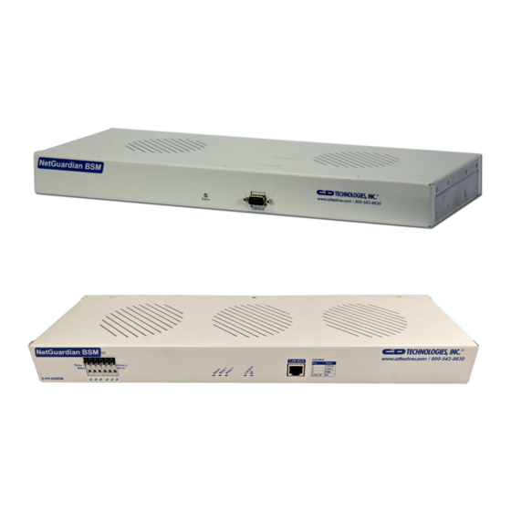
Fig. 1.1 The NetGuardian BSM can be flush or rear-mounted The NetGuardian BSM mounts in a 19" rack or a 23" rack using the provided rack ears for each size. Two rack ear locations are provided. Attach the appropriate rack ears in the flush-mount or rear-mount locations shown in Figure 1.1. -
Page 10: Configuration
LED is lit. To confirm that power is correctly connected, the front panel status LED will flash RED and GREEN, indicating that the firmware is booting up. Configuration To configure the NetGuardian BSM, you'll need a PC with terminal emulator, such as HyperTerminal... -
Page 11: Netguardian Bsm Front And Back Panel
NetGuardian BSM Front and Back Panel NetGuardian BSM Front Panel NetGuardian BSM Back Panel Status Description Status Flashing Green Application Running Flashing Red Bootloader Running Transmit to CAN Network Receive from CAN Network Transmit to NetGuardian RS232 Receive from NetGuardian... -
Page 12: Netguardian Bsm G2 Front And Back Panel
NetGuardian BSM G2 Front and Back Panel NetGuardian BSM G2 Front Panel NetGuardian BSM G2 Back Panel Front Panel Status Description Status Flashing Green Application Running Flashing Red Bootloader Running Flashing Green Transmit to CAN Network CAN-BUS Flashing Red Receive from CAN Network... -
Page 13: Data Ports
Data Ports Included CANBUS Termination Adapter DB-9 CAN Connector on NetGuardian BSM - CAN DB-9 Connection (G1 only) Pinout Diagram Included CANBUS Termination Adapter RJ45 CAN Connection - RJ45 Connection NGBSM RJ45 Adaptor NGBSM G2 RJ45 Port... -
Page 14: Quick Start: How To Connect To The Netguardian Bsm
Quick Start: How to Connect to the NetGuardian BSM Most NetGuardian BSM users find it easiest to give the unit an IP address, subnet and gateway through the front craft port (TTY interface) to start. Once these settings are saved and you reboot the unit, you can access it over LAN to do the rest of your databasing via the Web Browser interface. - Page 15 2. Select "Install from a list or specific location (Advanced)" 3. Click "Next >" 4. Select "Search for the best driver in these locations." 5. Insert NetGuardian BSM Resource Disc (CD) into your PC. 6. Click "Browse"...
- Page 16 7. Select the "Driver" folder of your NetGuardian BSM Resource Disc Disc (CD) and click "OK" The following message will confirm installation of a new "USB Communications Port" 8. Click "Finish" to close the Wizard. Now that the driver has been installed, a new COM port is being emulated on your PC. Before using hyperterminal, you must confirm the identity of that new COM port (COM1, COM2, COM3...) in the Windows...
- Page 17 9. Right-click the "My Computer" icon on your desktop, then click "Manage" 10.Click "Device Manager" in the left pane.
- Page 18 11.Expand the "Ports (COM & LPT)" section in the right pane. Look for "USB Communications Port (COMx)". Note the number of the COM port ("COM3" in the example above). 12.Click on the Start menu > select Programs > Accessories > Communications > HyperTerminal. 13.
- Page 19 Once connected, you will see a blank, white HyperTerminal screen. Press Enter to activate the configuration menu. 17. The NetGuardian BSM's main menu will appear. 18. ESC to the main menu. When asked if you'd like Type C for C)onfig, then E for E)thernet. Configure the to save your changes, type Y for Y)es.
- Page 20 6. Provision the NetGuardian BSM with the appropriate information, then change your computer's IP address and subnet mask back to their original settings. Now you're ready to do the rest of your configuration via LAN. Plug your LAN cable into the NetGuardian BSM and enter your username and password.
-
Page 21: Tty Interface
TTY Interface The TTY interface is the NetGuardian BSM's built-in interface for basic configuration. From the TTY interface, you can: · Edit the IPA, subnet, and gateway · Set DCP info for T/Mon polling · Configure primary port · Ping other devices on the network ·... -
Page 22: Quick Turn Up
1. Plug in all the batteries you would like to monitor. 2. Enable polling, save, write, and reboot. 3. Wait for the "Discovery Delay" (default 60 seconds) to make sure the NetGuardian BSM has time to find the batteries. 4. Click "Sync". - Page 23 1. Log in using telnet to port 2002 or the USB Craft port and press 'B' for BMS. 2. Press 'D' to force a discovery cycle to detect new batteries. Battery identifies and CAN addresses will be printed in hexadecimal. 3.
-
Page 24: How To Send Snmp Traps
How to Send SNMP Traps 1. Click on the SNMP button in the Provisioning menu. Enter the SNMP GET and SNMP SET community strings for your network, then click Save. The typical SNMP SET and GET community strings for network devices is "public". - Page 25 4. At the SNMP Notification screen, you'll enter your network's SNMP settings. Enter the IP address of your SNMP Trap Server. Enter the Trap Port Number (usually 162) and the Trap Community password. Click Save and Next. 5. At the Schedule screen, you'll select the exact days/times you want to receive SNMP notifications. You can set 2 schedules per notification.
-
Page 27: How To Send Email Notifications
How to Send Email Notifications 1. Click on the Notifications button in the Provisioning menu. You can setup as many as 8 different notifications. Begin the setup "wizard" by clicking Edit for a notification number. In this example, we'll setup Notification 1 to send emails. - Page 28 4. At the Schedule screen, you'll select the exact days/times you want to receive email notifications. You can set 2 schedules per notification. For example, you may want to receive notifications at certain times during the week, and at different hours on the weekend. Use the check boxes to select the days of the week, and select the time from the drop down menus.
-
Page 29: Lan Security
LAN Security The Telnet interface is available on TCP port 2002. It is enabled by default per section 10.1 LAN Lockdown. The web interface is available on the HTTP port 80 and HTTPS (SSLv3) port 443. Both are enabled by default. -
Page 30: Provisioning Menu Field Descriptions
Provisioning Menu Field Descriptions NetGuardian BSM configuration is performed from the Provisioning menus, the menu options in green on the left- side of the web interface. The following pages provide a brief description of the options available in each menu. -
Page 31: System
Name A name for this NetGuardian BSM unit. {Optional field) Location The location of this NetGuardian BSM unit. {Optional field) Contact telephone number for the person responsible for this NetGuardian BSM unit. Contact {Optional field) TRIP Unit ID Site number used when communicating over dialup with T/Mon. -
Page 32: 11.1.1 Bms Interrogator
11.1.1 BMS Interrogator BMS Interrogator Polling Enabled Check to monitor CAN Network. Notifications Report critical alarms via SNMP Trap or email (See Section 9.1) Polling Delay Time between polling string of batteries. Default 10 sec. Timeout How long BMS has to respond before it is considered not detected. Default 1 sec. -
Page 33: User Profiles
User Profiles Clicking User Profiles gives you access to modify the default username and password, and to edit the administrator profile and create up to 9 additional unique user profiles, each with different access rights to the NetGuardian BSM's web interface. -
Page 34: Ethernet
Unit IP IP address of the NetGuardian BSM. A road sign to the NetGuardian BSM, telling it whether your packets should stay on your Subnet Mask local network or be forwarded somewhere else on a wide-area network. An important parameter if you are connected to a wide-area network. It tells the Gateway NetGuardian BSM which machine is the gateway out of your local network. -
Page 35: Radius
RADIUS (Remote Authentication Dial In User Service) is an industry-standard way to manage logins to many different types of equipment in one central location. The NetGuardian BSM connects to your central RADIUS server. Every time a device receives a login attempt (usually a username & password), it requests an authentication from the RADIUS server. -
Page 36: Can 232 (G1 Only)
11.5 CAN 232 (G1 only) The Provisioning > CAN 232 menu allows you to change settings depending on the port type of your NetGuardian BSM. From this menu, you can select a mode of operation and enable reach-through serial port functionality. The Provisioning >... -
Page 37: Snmp
Community name for SNMP requests. Set Community Community name for SNMP SET requests. This field defines how the NetGuardian BSM unit may be accessed via SNMP. This can be set to the following: Read and Write · Access Disabled- Restricts all access to unit via SNMP Access ·... -
Page 38: Notifications
11.7 Notifications From the initial Provisioning > Notifications menu, you will see which of the 8 notifications are enabled, their server, and schedule. Click on the Edit link for one of the notifications to begin configuration. Once you've chosen which notification you want to setup, check the Enable Notification to turn it "on." Then choose a notification method, either email, SNMP, or Syslog. - Page 39 who will receive email alarm notifications. User Name User name for the Gmail account being used. Password Password for the Gmail account being used. Note: If you want to send authenticated emails, click the appropriate radio button. If you enable POP authentication, you will have to enter the relevant authentication information the fields below.
- Page 40 message Severity: Used to determine the severity of the message being logged.
-
Page 41: 11.7.2 Schedule
11.7.2 Schedule The notifications scheduling menu is where you will tell the NetGuardian exactly which days and times you want to receive alarm notifications. You set 2 different schedules for each. The Schedule creation screen Notification Scheduling From either Schedule 1 or 2, check which days you want to receive Days of the week notifications. -
Page 42: Alarms (G2 Only)
11.8 Alarms (G2 only) If your NetGuardian was built with discrete alarms, they are configured from the Provisioning > Alarms menu. Descriptions for the alarm points, polarity (normal or reversed) and notification type(s) are defined from this menu. You also have the option to use Basic or Advanced configuration methods, explained in this section. The Provisioning >... -
Page 43: Controls (G2 Only)
11.9 Controls (G2 only) The NetGuardian BSM G2 has two control relays that can be configured in the Provisioning > Controls menu. You can enter your own description for these relays and designate them to a notification device(s). The Provisioning > Controls screen Basic Controls Configuration ID number for the control relay. -
Page 44: Ping Targets
11.10 Ping Targets The Provisioning > Ping Targets menu allows you to configure the Description, IP Address, and Notification Devices for each of your ping targets. The Provisioning > Ping Targets menu Provisioning Ping Targets ID number for the ping target. Enab Check this box to enable the ping target. -
Page 45: System Alarms
11.11 System Alarms See "Display Mapping" in the Reference Section for a complete description of system alarms. The Provisioning > System Alarms menu Editing System Alarms Pnt (Point) The system alarm point number Non-editable description for this System (housekeeping) Description Alarm. -
Page 46: Battery Alarms
11.12 Battery Alarms The Provisioning > Battery Alarms menu allows you to configure which battery states should trigger an alarm, and which relay (if any) should be latched when an alarm is triggered. For each non-configurable alarm point, the drop-down menu allows you to select whether the triggered alarm will latch Relay 1 (signifying a Major alarm), Relay 2 (signifying a Minor alarm), or no relay at all. -
Page 47: Timers
11.13 Timers Enter the amount of time in seconds (sec) or minutes (m), in each value field and click Save. The Provisioning > Timers menu... -
Page 48: Date And Time
Select your time zone from the drop-down menu. Adjust Clock for Daylight Savings Time (DST) Enable DST Check this box to have the NetGuardian BSM observe Daylight Savings. Start Day Select the month, weekday, and time when Daylight Savings will begin. -
Page 49: Monitoring Via The Web Browser
Monitoring via the Web Browser 12.1 Alarms (G2 only) This selection provides the status of the base alarms by indicating if an alarm has been triggered. Under the State column, the status will appear in red if an alarm has been activated. The status will be displayed in green when the alarm condition is not present. -
Page 50: Controls (G2 Only)
MOM release before latching again. View and operate control relays from the Monitor > Controls menu Control Relay Operation ID number for the control relay. Description for the NetGuardian BSM G2's control relay defined in the Provisioning > Description Controls menu. State Status of the control relay. -
Page 51: Ping Targets
12.4 System Alarms System alarms are not-editable, housekeeping alarms that are programmed into NetGuardian BSM and BSMG2. The Monitor > System Alarms screen provides the status of the system alarms by indicating if an alarm has been triggered. Under the State column, the status will appear in red if an alarm has been activated. The status will be displayed in green when the alarm condition is not present. -
Page 52: Battery Alarms
12.5 Battery Alarms Each battery is monitored independently according the non-configurable set of alarms in Provisioning > Battery Alarms. Select a battery to monitor via the drop-down menu in the Monitor > Battery Alarms sidebar on the left. Monitor > Battery 2 Alarms 12.6 Battery Stats The Monitor >... -
Page 53: Device Access Descriptions
The Device Access options, listed in pink on the left side of the web interface, provide options for generating reports, updating the NetGuardian BSM's firmware, and rebooting the unit. Click any of the options under Device Access to perform the desired action. -
Page 54: Backup Configuration
Backup Configuration With the NetGuardian BSM you can backup your current configuration from the Web Interface. These configuration files can then be uploaded later, or uploaded to other NetGuardian BSM units. The Back up Config tab is located in the Device Access menu shown above. -
Page 55: Firmware Upgrade
Firmware Upgrade To access the Firmware Load screen, click on the Provisioning > System menu. At the bottom of this screen, click the Restore Configuration link located in the System Controls section. To upload firmware, click on Upload on the top right corner of the web interface At the Firmware Load screen, simply browse for the firmware update you've downloaded from www.dpstele.com and click Load. -
Page 56: Reference Section
Reference Section 16.1 Display Mapping Display Mapping Display Point Description Alarms 1-4 5-16 Undefined 17-20 Control Relays 1-4 21-32 Undefined Default configuration DIP Switch Config MAC Address Not Set IP Address Not Set LAN Hardware Error SNMP Processing Error SNMP community error LAN TX packet drop Notification 1 failed Notification 2 failed... - Page 57 25-32 Battery #1 Type ID 33-40 Battery #1 Type Switch Setting 41-48 Battery #1 Firmwre/Hardware Match 49-64 Undefined Display Point Description Undefined Battery #1 Not Detected Battery #1 Sent to Sleep 4-32 Undefined Battery #1 Operation Mode: Initializing Battery #1 Operation Mode: Wake-Up Battery #1 Operation Mode: Validating Battery #1 Operation Mode: Post Battery #1 Operation Mode: Normal...
- Page 58 Display Point Description Battery #2 Software Version 9-16 Battery #2 Software Revision 17-24 Battery #2 Hardware Version Display 10 25-32 Battery #2 Type ID 33-40 Battery #2 Type Switch Setting 41-48 Battery #2 Firmware/Hardware Match 49-64 Undefined Display Point Description Undefined Battery #2 Not Detected Battery #2 Sent to Sleep...
- Page 59 33-48 Battery #2 Number of Complete Discharge Cycles 49-64 Battery #2 Usable Capacity (Ahr) Display Point Description Display 15 1-64 Battery #3 Serial Number Display Point Description Battery #3 Software Version 9-16 Battery #3 Software Revision 17-24 Battery #3 Hardware Version Display 16 25-32 Battery #3 Type ID...
- Page 60 49-64 Battery #3 Estimated Runtime (minutes) Display Point Description 1-16 Battery #3 Design Max Capacity (Ahr) 17-32 Battery #3 State of Health (%) Display 20 33-48 Battery #3 Number of Complete Discharge Cycles 49-64 Battery #3 Usable Capacity (Ahr) Display Point Description Display 21...
- Page 61 Display Point Description 1-16 Battery #4 Remaining Capacity (Ahr) 17-32 Battery #4 Average Cell Temperature (°C/ °F) Display 25 33-48 Battery #4 Nominal Float Voltage (VDC) 49-64 Battery #4 Estimated Runtime (minutes) Display Point Description 1-16 Battery #4 Design Max Capacity (Ahr) 17-32 Battery #4 State of Health (%) Display 26...
- Page 62 Display Point Description 1-16 Battery #5 Current (A) 17-32 Battery #5 Max Current (A) Display 30 33-48 Battery #5 State of Charge (%) 49-64 Battery #5 Voltage (VDC) Display Point Description 1-16 Battery #5 Remaining Capacity (Ahr) (°C/ °F) 17-32 Battery #5 Average Cell Temperature Display 31 33-48...
- Page 63 Battery #6 High Voltage: Warning Battery #6 High Voltage: Alarm Battery #6 High Voltage: Lock-Out 58-64 Undefined Display Point Description 1-16 Battery #6 Current (A) 17-32 Battery #6 Max Current (A) Display 36 33-48 Battery #6 State of Charge (%) 49-64 Battery #6 Voltage (VDC) Display...
- Page 64 Battery #7 Temperature: Warning Battery #7 Temperature: Alarm Battery #7 Temperature: Lock-Out Battery #7 Low Voltage: Warning Battery #7 Low Voltage: Alarm Battery #7 Low Voltage: Lock-Out Battery #7 High Voltage: Warning Battery #7 High Voltage: Alarm Battery #7 High Voltage: Lock-Out 58-64 Undefined Display...
- Page 65 Battery #8 Charge Mode: Discharge Battery #8 Charge Mode: Charge Complete Battery #8 Current: Warning Battery #8 Current: Alarm Battery #8 Current: Lock-Out Battery #8 Temperature: Warning Battery #8 Temperature: Alarm Battery #8 Temperature: Lock-Out Battery #8 Low Voltage: Warning Battery #8 Low Voltage: Alarm Battery #8 Low Voltage: Lock-Out Battery #8 High Voltage: Warning...
- Page 66 Battery #9 Operation Mode: Lock-Out Battery #9 In Lock-Out Battery #9 Charge Mode: Initializing Battery #9 Charge Mode: Float Battery #9 Charge Mode: Charge Battery #9 Charge Mode: Discharge Battery #9 Charge Mode: Charge Complete Battery #9 Current: Warning Battery #9 Current: Alarm Battery #9 Current: Lock-Out Battery #9 Temperature: Warning Battery #9 Temperature: Alarm...
- Page 67 4-32 Undefined Battery #10 Operation Mode: Initializing Battery #10 Operation Mode: Wake-Up Battery #10 Operation Mode: Validating Battery #10 Operation Mode: Post Battery #10 Operation Mode: Normal Battery #10 Operation Mode: Lock-Out Battery #10 In Lock-Out Battery #10 Charge Mode: Initializing Battery #10 Charge Mode: Float Battery #10 Charge Mode: Charge Battery #10 Charge Mode: Discharge...
-
Page 68: System Alarms
16.2 System Alarms Display Point Description Default Configuration DIP Switch Configuration MAC Address Not Set IP Address Not Set LAN hardware error SNMP Process Error SNMP Community Error LAN TX packet drop Notification 1 Failed Notification 2 Failed Notification 3 Failed Notification 4 Failed Notification 5 Failed Notification 6 Failed... -
Page 69: Snmp Manager Functions
16.3 SNMP Manager Functions The SNMP Manager allows the user to view alarm status, set date/time, issue controls, and perform a resync. The display and tables below outline the MIB object identifiers. The table below begins with dpsRTU; however, the MIB object identifier tree has several levels above it. -
Page 70: Snmp Granular Trap Packets
BSM. SNMP Trap managers can use one of two methods to get alarm information: 1. Granular traps (not necessary to define point descriptions for the NetGuardian BSM) OR 2. The SNMP manager reads the description from the Trap. UDP Header... -
Page 71: Frequently Asked Questions
Q. How do I connect my NetGuardian BSM to the LAN? A. To connect your NetGuardian BSM to your LAN, you need to configure the unit IP address, the subnet mask and the default gateway. A sample configuration could look like this: Unit Address: 192.168.1.100... -
Page 72: Snmp Faqs
A. SNMP v1, SNMPv2 and SNMPv3. Q. How do I configure the NetGuardian BSM to send traps to an SNMP manager? Is there a separate MIB for the NetGuardian BSM? How many SNMP managers can the agent send traps to? And how do I set the IP address of the SNMP manager and the community string to be used when sending traps? A. -
Page 73: Technical Support
3. Have access to troubled equipment. Please be at or near your equipment when you call DPS Telecom Technical Support. This will help us solve your problem more efficiently. 4. Call during Customer Support hours. -
Page 74: End User License Agreement
DPS Telecom which arise out of or are related to the non-fulfillment of any covenant or obligation of End User in connection with this Agreement. - Page 75 Warranty DPS Telecom warrants, to the original purchaser only, that its products a) substantially conform to DPS' published specifications and b) are substantially free from defects in material and workmanship. This warranty expires two years from the date of product delivery with respect to hardware and ninety days from the date of product delivery with respect to software.
- Page 76 Free Tech Support is Only a Click Away Need help with your alarm monitoring? DPS Information Services are ready to serve you … in your email or over the Web! www.DpsTelecom.com Free Tech Support in Your Email: The Protocol Alarm Monitoring Ezine The Protocol Alarm Monitoring Ezine is your free email tech support alert, delivered directly to your in-box every two weeks.
Need help?
Do you have a question about the NetGuardian BSM and is the answer not in the manual?
Questions and answers