Table of Contents
Advertisement
Quick Links
Advertisement
Table of Contents

Related Manuals for AXIOMTEK MVS900-511-FL Series


Summary of Contents for AXIOMTEK MVS900-511-FL Series
- Page 1 MVS900-511-FL series MVS900-512-FL series Fanless Vision System User’s Manual...
- Page 2 Disclaimers This manual has been carefully checked and believed to contain accurate information. Axiomtek Co., Ltd. assumes no responsibility for any infringements of patents or rights of any third party, or any liability arising from such use. Axiomtek does not warrant or assume any legal liability or responsibility for the accuracy, completeness or usefulness of any information in this document.
- Page 3 When handling boards and components, wear a grounding wrist strap available from most electronic component stores. Trademarks Acknowledgments Axiomtek is a trademark of Axiomtek Co., Ltd. ® Windows is a trademark of Microsoft Corporation. IBM, PC/AT, PS/2, VGA are trademarks of International Business Machines Corporation.
-
Page 4: Table Of Contents
Table of Contents Disclaimers ..................... ii ESD Precautions ................... iii Section 1 Introduction ..........1 General Description ................1 System Specifications ................ 2 1.2.1 Main CPU Board ..................2 1.2.2 I/O System ....................3 1.2.3 Vision I/O (D-sub 44-pin connetor) .............. 4 Dimensions .................. - Page 5 Wall-mount bracket kit ..............32 Din-rail bracket kit ................34 Section 3 I/O Connection ........... 35 I/O Connection (44-pin female I/O connector) ........ 35 3.1.1 Isolated Digital Input .................. 35 3.1.2 Isolated Digital Output ................36 3.1.3 Isolated Trigger/Latch Input ............... 36 3.1.4 Isolated Trigger Output ................
- Page 6 How to Use Watchdog Timer ............71 Sample Program ................72...
-
Page 7: Section 1 Introduction
MVS900-511/512-FL Section 1 Introduction This section contains general information and detailed specifications of the MVS900 Series Vision System, including the following sections: General Description Features Specifications Dimensions General Description The MVS900-511/512-FL integrates camera interfaces and various I/O features for machine vision applications, including GigE camera support, trigger input and output with microsecond-scale real-time control, as well as LED lighting output with constant current control. -
Page 8: System Specifications
MVS900-511/512-FL 2 CH quadrature encoder input 16 CH isolated DI; 16 CH isolated DO Supports camera interfaces 4 IEEE802.3at GbE LAN ports (PoE) 4 USB 3.0 ports Power input: 24 VDC (uMin=19V/uMax=30V) -10°C to +60°C operating temperature range with W.T. SSD ... -
Page 9: 1.2.2 I/O System
MVS900-511/512-FL System memory Two DDR4-2133/2400 un-buffered SO-DIMM max. up to 32GB 1.2.2 I/O System Standard I/O interface One ATX power on/off switch One ATX/AT Mode switch One Reset switch One 2-pin connector output for remote power on/off switch ... -
Page 10: Vision I/O (D-Sub 44-Pin Connetor)
MVS900-511/512-FL 1 x M.2 M key slot 2280 with PCIe x4 signal (only for MVS900-512-FL) Camera interface 4 x IEEE802.3at GbE LAN port (PoE, Intel® i210-AT, IEEE802.3at compliant, total max. power output 30W) 1.2.3 Vision I/O (D-sub 44-pin connetor) ... - Page 11 MVS900-511/512-FL Encoder FIFO Number of channel: 2 FIFO depth: 1024x32-bit Interrupt type: Empty/ Almost Empty (Almost empty: FIFO data number is less than 1/3) Auto reload: Yes. After compared, the next FIFO data will reload to FIFO storage. ...
-
Page 12: Dimensions
MVS900-511/512-FL Connector: 4CH LED lighting control via an 8-pin terminal connector Dimensions Introduction... -
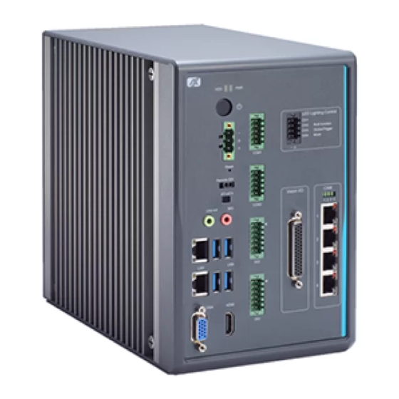
Page 13: I/O Outlet
MVS900-511/512-FL I/O Outlet The following figure shows you the I/O outlets on the front and rear panels of the MVS900 Series. Introduction... -
Page 14: Packing List
Foot pad x 4 CPU grease x 1 Power connector x 1 Terminal block x 5 Remote switch cable x 1 If you cannot find this package or any items are missing, please contact Axiomtek distributor immediately. Introduction... -
Page 15: Jumper Settings
MVS900-511/512-FL Jumper Settings Properly configure jumper settings on the SBC87511/SBC87512 to meet your application purpose. Below you can find a summary table of all jumpers and onboard default settings. Note: How to setup Jumpers Illustrations below show that a cap on a jumper is to “close” the jumper, whereas that off a jumper is to “open”... -
Page 16: Connectors
MVS900-511/512-FL Connectors Connectors connect the board with other parts of the system. Loose or improper connection might cause problems. Make sure all connectors are properly and firmly connected. Here is a table summarizing all connectors on the board. Connector Section MINI Card slot 1.8.1 LAN+USB3.0... -
Page 17: Mini Card Slot
MVS900-511/512-FL 1.7.1 MINI CARD SLOT There is a PCI-Express Mini Card connector on the top side. It supports a USB signal for MVS900-511-FL. In addition, MVS900-512-FL can support USB and PCIe signals. Pins Signals Pins Signals WAKE# +3.3VSB No use No use +1.5V CLKREQ#... -
Page 18: Lan+Usb3.0
MVS900-511/512-FL 1.7.2 LAN+USB3.0 The system has two RJ-45 connectors: LAN1 and LAN2. Ethernet connection can be established by plugging one end of the Ethernet cable into this RJ-45 connector and the other end (phone jack) to a 1000/100/10-Base-T hub. 1000 100/10 Pins Descriptions... -
Page 19: Vga Connector
MVS900-511/512-FL The Universal Serial Bus connectors are compliant with USB 3.0 (5Gb/s), ideal for connecting USB peripherals to the system, such as scanners, cameras and USB devices, etc. Signal USB Port 0 Signal USB Port 1 USB_VCC (+5V level standby power) USB_VCC (+5V level standby power) USB_Data3- USB_Data2-... -
Page 20: Dc-In Phoenix Power Connector
MVS900-511/512-FL 1.7.4 DC-in Phoenix Power Connector These two audio jacks are used for Audio Mic-In and Audio Line-out. Pins Signals Line out Microphone In 1.7.5 DC-in Phoenix Power Connector The system supports 24VDC (uMin=19V/uMax=30V) Phoenix DC-in connector for system power input. Pins Signals 1.7.6... -
Page 21: Sata Power Connector
MVS900-511/512-FL 1.7.7 SATA Power connector Use SCN1 and SCN2 for interfacing to SATA 2.5" HDD power supply. Pins Signals +12V level +5V level 1.7.8 SATA Connector (SATA1、SATA2) These Serial Advanced Technology Attachment (Serial ATA or SATA) connectors are used as high-speed SATA interfaces. -
Page 22: At/Atx Switch
MVS900-511/512-FL 1.7.10 AT/ATX Switch If you set AT/ATX switch to AT mode, the system will be automatically powered on without pressing soft power button during power input; we can use this switch to achieve auto power on demand. 1.7.11 Reset Button The Reset button allows users to reset the system. -
Page 23: 8-Pin Terminal Connector For Led Lighting Control
MVS900-511/512-FL 1.7.13 8-Pin Terminal Connector for LED Lighting Control The 8-pin terminal connector supports 4CH LED output for a variety of illumination. Description Description LED1 - LED1 + LED2 - LED2 + LED3 - LED3 + LED4 - LED4 + 1.7.14 44-Pin Female I/O Connector The 44-pin D-SUB female I/O connector has special I/O functions, including encoder input,... -
Page 24: Isolated Com & Dio I/O
MVS900-511/512-FL 1.7.15 Isolated COM & DIO I/O The system has two serial ports & DIO, including COM1~COM2* with isolated 1.5KVDC protection and DIO1~DIO2 8-in/8-out isolated 1.5KVDC DIO ports. *RS-232/422/485 can be configured via BIOS settings (Refer to website about SDK, driver and test tool.) ※COM1,COM2,DIO1,DIO2 CN1 (COM1)&... -
Page 25: Pd Power Indicator & Cam1 ~ Cam4 Connector
MVS900-511/512-FL CN3(DIO1) CN4(DIO2) Function Function Common1 PWR+ Common2 PWR+ DO10 DO20 DO11 DO21 DO12 DO22 DO13 DO23 Common 1 PWR- Common 2 PWR- External 1 Power External 2 Power DI10 DI20 DI11 DI21 DI12 DI22 DI13 DI23 Isolation 1 GND Isolation 2 GND 1.7.16 PD Power Indicator &... - Page 26 MVS900-511/512-FL PD Power Indicator When a CAM port is currently active, its corresponding PD power indicator will light up. Signal CAM Port1 CAM Port2 CAM Port3 CAM Port4 CAM1 ~ CAM4 Connector Description Active LED: Amber LED1 Off: No link Blinking: Data activity detected LED2 Link LED (10/100-Green;...
-
Page 27: M.2 2280 Key M Slot Nvme Ssd
MVS900-511/512-FL 1.7.17 M.2 2280 Key M slot NVMe SSD The MVS900-512-FL comes with one M.2 2280 Key M slot (Gen.3 PCIex4 signal) for storage. Signal Signal Signal Signal +3.3V +3.3V PERn3 PERp3 LED_1# PETn3 +3.3V PETp3 +3.3V +3.3V PERn2 +3.3V PERp2 PETn2 PETp2... - Page 28 MVS900-511/512-FL This page is intentionally left blank. Introduction...
-
Page 29: Section 2 Hardware Installation
MVS900-511/512-FL Section 2 Hardware Installation The MVS900 Series is convenient for your various hardware configurations, including the CPU (Central Processing Unit), memory module, HDD (Hard Disk Drive) and PCIe/PCI card. Section 2 will show you how to install the hardware. Installing the Processor ®... - Page 30 MVS900-511/512-FL Procedure of Installation: Step 1 Turn off the system. Step 2 Disconnect the power connector. Step 3 Loosen screws to remove the heatsink cover from the chassis. Step 4 After opening the heatsink cover, you can locate the CPU socket as marked. Align pins of the CPU with pin holes of the socket.
-
Page 31: Installing The Memory Module
MVS900-511/512-FL Step 5 Apply thermal grease on top of the CPU Step 6 After installing all components, close the heatsink cover back to the chassis and fasten all screws. Installing the Memory Module Step 1 Turn off the system. Step 2 Disconnect the power connector. -
Page 32: Installing The Hard Disk Drive
MVS900-511/512-FL Step 4 Install the SO-DIMM (small outline dual in-line memory module) into the socket and push it firmly down until it is fully seated. The socket latches are clipped on to the edges of the memory module. Step 5 After installing the memory modules, please close the heatsink cover back to the chassis and fasten all screws. - Page 33 MVS900-511/512-FL Step 6 Fix the HDD onto the HDD1 bracket with four screws and HDD2 bracket with two screws. Step 7 Insert and screw the HDD1 module into the HDD bay. Step 8 Insert and screw the HDD2 module, on top of the HDD1 module. Step 9 Screw the backplane back to the system.
-
Page 34: Installing Foot Pad
MVS900-511/512-FL Installing foot pad The MVS900 series provides four foot pad. Step 1 Turn off the system. Step 2 Disconnect the power connector. Step 3 Take the foot pads from the accessory pack. Turn the system upside and then screw the foot pads into system. Hardware Installation... -
Page 35: Installing M.2 2280 Key M Ssd Module
MVS900-511/512-FL Installing M.2 2280 Key M SSD Module The MVS900-512-FL provides M.2 2280 Key M slot for SSD storage. Step 1 Turn off the system. Step 2 Disconnect the power connector. Step 3 Turn the system upside down to locate and then unscrew the screws at the bottom side. - Page 36 MVS900-511/512-FL Step 5 Hold the M.2 2280 Key M SSD storage module at 30 degree up from horizontal direction and inset the golden finger into the slot until fully inserted. Step 6 Fix the SSD storage onto the board with one screw. Hardware Installation...
-
Page 37: Installing Internal Usb Dongle (Option)
MVS900-511/512-FL Installing internal USB dongle (Option) The MVS900 series support internal USB2.0 slot for software dongle. Step 1 Turn off the system. Step 2 Disconnect the power connector. Step 3 Turn the left side of the system to locate and then unscrew the screws; furtherly, open the cover. -
Page 38: Wall-Mount Bracket Kit
MVS900-511/512-FL Wall-mount bracket kit Get 4pcs truss head M4*6L screws to fix the wall-mount kit from optional wall-mount kit. Hardware Installation... - Page 39 MVS900-511/512-FL Note: If you install the screws in drywall, use the hollow wall anchors to ensure that unit does unit pull away from the wall due to prolonged strain the cable and power connector. Hardware Installation...
-
Page 40: Din-Rail Bracket Kit
MVS900-511/512-FL Din-rail bracket kit Get 4pcs truss head M3*5L screws to fix the wall-mount kit from optional din-rail kit. Hardware Installation... -
Page 41: Section 3 I/O Connection
MVS900-511/512-FL Section 3 I/O Connection I/O Connection (44-pin female I/O connector) Refer to this section to connect any cables between the system and other devices. Each of the following I/O figures illustrates their respective connection on the MVS900. 3.1.1 Isolated Digital Input The figure shows how to connect between external input source and the system. -
Page 42: Isolated Digital Output
MVS900-511/512-FL 3.1.2 Isolated Digital Output The figure shows how to connect between an output channel and the system. If an external voltage 5~30 VDC is applied to an isolated output channel, the current will flow from the external voltage source to the system. Please note that the current through each DO channel should not exceed 200 mA. -
Page 43: Isolated Trigger Output
MVS900-511/512-FL 3.1.4 Isolated Trigger Output The figure shows how to connect between an output channel and the system. If an external voltage 5~30 VDC is applied to an isolated output channel, the current will flow from the external voltage source to the system. Please note that the current through each trigger output channel should not exceed 100 mA. -
Page 44: I/O Connection
MVS900-511/512-FL Open Collector Type: I/O Connection The system offers 8-in/8-out DIO ports with isolated 1.5KVDC as the red box of the figure below. Refer to this section to connect any cables between the flexible I/O and other devices. 3.2.1 Isolated Digital Input The figure shows how to connect between external input source and the system. -
Page 45: Isolated Digital Output
MVS900-511/512-FL 3.2.2 Isolated Digital output The figure shows how to connect between an output channel and the system. If an external voltage 12~24 VDC is applied to an isolated output channel, the current will flow from the external voltage source to the system. Please note that the current through each DO channel should not exceed 200 mA. - Page 46 MVS900-511/512-FL This page is intentionally left blank. I/O Connection...
-
Page 47: Section 4 Operating
MVS900-511/512-FL Section 4 Operating Operating This section describes the detail operation of the MVS900. 4.1.1 Encoder function The MVS900 supports 2CH 32-bit incremental quadrature encoder input for the ABZ signal by a mode x1, x2 or x4, which is used for applications where direction sensing is required. This mode consists of two square-wave pulse signals known as Phase A and Phase B, which are generated by a rotating encoder. -
Page 48: Bounce Filter
MVS900-511/512-FL The figure below depicts a case where a valid encoder value is pulse edge from phase A encoder signal. The 1/2, 1/3 or 1/4 mode defines the number of pulses to skip between valid acquisition. After the following pulses meet mode setting, the encoder value will be increasing (As defined by the selection of 1/2, 1/3 or 1/4 mode). -
Page 49: Encoder Linear Trigger
MVS900-511/512-FL 4.1.4 Encoder Linear Trigger This function is able to compare counter value by an encoder linear function. Each encoder supports two linear functions and has four parameters of configuration as below: Start Point, Repeat Times, Interval and Direction. Trigger Point (N+1) = Trigger Point N + Interval (N = Repeat Times, the first trigger condition is start point.) Trigger output will generate an output signal when Trigger Point equals the current counter... -
Page 50: Trigger Input/ Output
MVS900-511/512-FL 4.1.7 Trigger Input/ Output Trigger input supports de-bounce filter function to help filter out environmental noise that can mix with normal encoder signals and affect the accuracy of the pulse count. The de-bounce filter defines the interval width for high/low signals. Signals with interval width less than the defined value will be filtered out. -
Page 51: Led Lighting Control
MVS900-511/512-FL Invert Trigger source mode can be set as rising trigger or falling trigger. Trigger Source Trigger Output Delay Time Rising Trigger Trigger Source Trigger Output Delay Time Falling Trigger 4.1.8 LED Lighting Control LED lighting output can be set to use Trigger or Strobe mode. Further, based on a variety of conditions, trigger LED output, duration time, delay time and dimming control are all programmable to help identify object characteristics and meet high image requirements in different inspections. -
Page 52: Application
MVS900-511/512-FL Application This section shows the real cases in the machine vision field. 4.2.1 Scenario 1 In this scenario, when an optical sensor or encoder detects objects passing down the production line, it will send trigger signals to notify the system. These signals trigger a camera to capture images. -
Page 53: Section 5 Ami Bios Utility
MVS900-511/512-FL Section 5 AMI BIOS Utility The AMI UEFI BIOS provides users with a built-in setup program to modify basic system configuration. All configured parameters are stored in a 16MB flash chip to save the setup information whenever the power is turned off. This chapter provides users with detailed description about how to set up basic system configuration through the AMI BIOS setup utility. -
Page 54: Navigation Keys
MVS900-511/512-FL Navigation Keys The BIOS setup/utility uses a key-based navigation system called hot keys. Most of the BIOS setup utility hot keys can be used at any time during the setup navigation process. These keys include <F1>, <F2>, <Enter>, <ESC>, <Arrow> keys, and so on. Note: Some of the navigation keys differ from one screen to another. -
Page 55: Main Menu
MVS900-511/512-FL Main Menu The first time you enter the setup utility, you will be in the Main setup screen. You can always return to the Main setup screen by selecting the Main tab. System Time/Date can be set up as described below. -
Page 56: Advanced Menu
MVS900-511/512-FL Advanced Menu The Advanced menu also allows users to set configuration of the CPU and other system devices. You can select any of the items in the left frame of the screen to go to the sub menus: ► Hardware Monitor ►... - Page 57 MVS900-511/512-FL Hardware Monitor This screen monitors hardware health. AMI BIOS Utility...
- Page 58 MVS900-511/512-FL EtherCAT Configuration Set “Disable” mode in the following 5 times to support the Ethercat. ACPI Sleep State Select the highest ACPI sleep state the system will enter when the suspend button is pressed. Configuration options are Suspend S3 only (Suspend to RAM). AMI BIOS Utility...
- Page 59 MVS900-511/512-FL Trusted Computing Select the Security Device Support to enable or disable the TPM function. AMI BIOS Utility...
- Page 60 MVS900-511/512-FL CPU Configuration This screen shows the CPU configuration, and you can change the value of the selected option. Hardware Prefetcher Turn on/off the MLC streamer prefetcher. Adjacent Cache Line Prefetch Turn on/off prefetching of adjacent cache lines. ...
- Page 61 MVS900-511/512-FL SATA Configuration You can read the current installed hardware configurations from those SATA ports in the SATA Configuration menu. During system boot up, BIOS will detect the present SATA devices automatically. SATA Controller(s) Enable or disable the SATA Controller feature. The default is Enabled. ...
- Page 62 MVS900-511/512-FL PCH-FW Configuration Display ME firmware information AMI BIOS Utility...
- Page 63 MVS900-511/512-FL USB Configuration USB configuration can be configured here by selecting and changing each item. A description of the selected item appears on the right side of the screen. USB Devices Displays all detected USB devices. Legacy USB Support Enables Legacy USB support.
- Page 64 MVS900-511/512-FL CSM Configuration The screen displays CSM information. CSM Support Enabled / Disable CSM Support. GateA20 Active UPON REQUEST - GA20 can be disabled using BIOS services. ALWAYS - do not allow disabling GA20. This option is useful when any RT code is executed above 1MB. ...
-
Page 65: Chipset Menu
MVS900-511/512-FL Chipset Menu The Chipset menu allows users to change the advanced chipset settings. You can select any of the items in the left frame of the screen to go to the sub menus: ► System Agent (SA) Configuration For items marked with “”, please press <Enter> for more options. AMI BIOS Utility... - Page 66 MVS900-511/512-FL System Agent (SA) Configuration This screen shows System Agent information and provides functions for specifying related parameters. For items marked with “”, please press <Enter> for more options. Graphics Configuration Use this item for graphics configuration settings. ...
- Page 67 MVS900-511/512-FL Display Select Allows you to select which graphics controller to use as the primary boot device. AMI BIOS Utility...
- Page 68 MVS900-511/512-FL Memory Configuration This screen shows Memory information. AMI BIOS Utility...
- Page 69 MVS900-511/512-FL PEG Port Configuration This screen shows Enable Root Port and Max Link function settings. Further, the next item provides functions for PEG Port Feature Configuration. For items marked with “”, please press <Enter> for more options. AMI BIOS Utility...
- Page 70 MVS900-511/512-FL PEG Port Feature Configuration This screen shows Detect Non-Compliance Device settings. AMI BIOS Utility...
- Page 71 MVS900-511/512-FL Module Configuration Serial Port 1~4 Configuration Use this item to set parameters of serial port 1 to 4. AMI BIOS Utility...
- Page 72 MVS900-511/512-FL Serial Port (1~2) Configuration COM Port Type Use this item to set parameters of RS232/422/485. AMI BIOS Utility...
-
Page 73: Security Menu
MVS900-511/512-FL Security Menu The Security menu allows users to change the security settings for the system. Administrator Password This item indicates whether an administrator password has been set (installed or uninstalled). User Password This item indicates whether an user password has been set (installed or uninstalled). AMI BIOS Utility... -
Page 74: Boot Menu
MVS900-511/512-FL Boot Menu The Boot menu allows users to change boot options of the system. Setup Prompt Timeout Number of seconds to wait for setup activation key. 65535(0xFFFF) means indefinite waiting. Bootup NumLock State Use this item to select the power-on state for the keyboard NumLock. ... -
Page 75: Save & Exit Menu
MVS900-511/512-FL Save & Exit Menu The Save & Exit menu allows users to load your system configuration with optimal or fail-safe default values. Save Changes and Exit When finishing the system configuration settings, select this option to leave Setup and return to Main Menu. - Page 76 MVS900-511/512-FL Discard Changes and Reset Select this option to quit Setup without making any permanent changes to the system configuration and reboot the computer. Select Discard Changes and Reset from the Save & Exit menu and press <Enter>. Select Yes to discard changes and reset. ...
-
Page 77: Appendix A Watchdog Timer
MVS900-511/512-FL Appendix A Watchdog Timer A.1 About Watchdog Timer Software stability is major issue in most applications. Some embedded systems are not watched by an operator for 24 hours. It is usually too slow to wait for someone to reboot when computer hangs. - Page 78 MVS900-511/512-FL Begin Begin Next Next Enable and Initialize Enable and Initialize Watchdog Timer Watchdog Timer Next Next Program “A” Program “A” Next Next Disable Watchdog Reset Watchdog Timer Timer Next Next A.3 Sample Program Assembly sample code: ;Enable WDT: dx,2Eh al,87 ;Un-lock super I/O dx,al...
- Page 79 MVS900-511/512-FL dx,al dx,2Fh al,01h dx,al ;Activate WDT: dx,2Eh al,0F0h dx,al dx,2Fh al,80h dx,al ;Set base timer : dx,2Eh al,0F6h dx,al dx,2Fh al,Mh ;M=00h,01h,...FFh (hex),Value=0 to 255 Note dx,al ;(see below) ;Set Second or Minute : dx,2Eh al,0F5h dx,al dx,2Fh Note al,Nh ;N=71h or 79h(see below)
- Page 80 MVS900-511/512-FL If N=79h, the time base is set to minute. M = time value 00: Time-out disable 01: Time-out occurs after 1 minute 02: Time-out occurs after 2 minutes 03: Time-out occurs after 3 minutes FFh: Time-out occurs after 255 minutes Watchdog Timer...
Need help?
Do you have a question about the MVS900-511-FL Series and is the answer not in the manual?
Questions and answers