AXIOMTEK UST500-517-FL Series User Manual
Embedded system
Hide thumbs
Also See for UST500-517-FL Series:
- User manual (83 pages) ,
- Quick installation manual (2 pages)
Table of Contents
Advertisement
Quick Links
Advertisement
Table of Contents

Related Manuals for AXIOMTEK UST500-517-FL Series


Summary of Contents for AXIOMTEK UST500-517-FL Series
- Page 1 UST500-517-FL Series Embedded System User’s Manual...
-
Page 2: Disclaimers
Disclaimers This manual has been carefully checked and believed to contain accurate information. Axiomtek Co., Ltd. assumes no responsibility for any infringements of patents or rights of any third party, or any liability arising from such uses. Axiomtek does not warrant or assume any legal liability or responsibility for the accuracy, completeness or usefulness of any information in this document. -
Page 3: Safety Precautions
Safety Precautions Before getting started, please read the following important safety precautions. The UST500-517-FL does not come with an operating system which must be loaded first before installation of any software into the computer. Be sure to ground yourself to prevent static charge when installing any internal components. -
Page 4: Classifications
Classifications Degree of production against electric shock: not classified Degree of protection against ingress of water: IP40* Equipment not suitable for use in the presence of a flammable anesthetic mixture with air, oxygen or nitrous oxide. Mode of operation: Continuous *Please refer the IP rating for UST500 SKUs in 1.6 Model List. -
Page 5: General Cleaning Tips
General Cleaning Tips Please keep the following precautions in mind while understanding the details fully before and during any cleaning of the computer and any components within. A piece of dry cloth is ideal to clean the device. Be cautious of any tiny removable components when using a vacuum cleaner to absorb dirt on the floor. -
Page 6: Scrap Computer Recycling
Scrap Computer Recycling Please inform the nearest Axiomtek distributor as soon as possible for suitable solutions in case computers require maintenance or repair; or for recycling in case computers are out of order. Trademarks Acknowledgments Axiomtek is a trademark of Axiomtek Co., Ltd. -
Page 7: Table Of Contents
Table of Contents Disclaimers ......................i Safety Precautions ....................iii Classifications ....................... iv General Cleaning Tips ................... v Scrap Computer Recycling ................... vi SECTION 1 INTRODUCTION ................ 1 General Descriptions ................. 1 System Specifications ............... 2 1.2.1 Driver Contents ....................4 Dimensions .................. - Page 8 3.2.2 Reset Button ....................42 Connectors ..................42 3.3.1 DC-in Power Connector ................42 3.3.2 HDMI Connector ..................... 43 3.3.3 DVI-D Connector .................... 43 3.3.4 VGA Connector ....................43 3.3.5 Serial Port Connector(COM1~COM2) ............44 3.3.6 Ethernet Connector (LAN1~LAN16) ............. 44 3.3.7 USB 3.0 Connector ..................
-
Page 9: Section 1 Introduction
UST500-517-FL Series user’s Manual SECTION 1 INTRODUCTION This section contains general information and detailed specifications of the UST500-517- FL.Section 1 consists of the following sub-sections: General Descriptions System Specifications Dimensions I/O Outlets Packing List ... -
Page 10: System Specifications
UST500-517-FL Series user’s Manual Features ® ® Core™ i7/i5/i3 & Celeron LGA1151 socket 7 generation Intel ® processor (Kaby Lake / Skylake) with Intel Q170 Supporting wide range of DC power input from 9 to 36VDC One DVI-D, one HDMI and VGA with triple view supported ... - Page 11 No Tray ---3Grm with SSD (5-500Hz, X, Y, Z directions) ---2Grm with HDD (5~500Hz, X,Y, Z directions) (must be used with the Axiomtek Anti-Vibration Kit; please contact Axiomtek for details) 2 SATA Tray ---3Grm with SSD (5-500Hz, X, Y, Z directions) ---2Grm with HDD (5~500Hz, X,Y, Z directions) (must be used with the Axiomtek Anti-Vibration Kit;...
-
Page 12: Driver Contents
2 SATA drive trays: 280 mm(11.02”)(W ) x 210.5 mm(8.27”)(D) x 83.7 mm(3.30”)(H) 4 SATA drive trays: 280 mm(11.02”)(W ) x 210.5 mm(8.27”)(D) x 99.2 mm(3.91”)(H) 1.2.1 Driver Contents Please download the drivers from the Axiomtek official website. Ethernet Chipset Graphic ... -
Page 13: Dimensions
UST500-517-FL Series user’s Manual 1.3 Dimensions The following diagrams show the dimensions and outlines of the UST500-517-FL. 1.3.1 UST500-517-FL FOR 4SATA TRAY Dimensions Introduction... -
Page 14: Ust500-517-Fl For 2Sata Tray Dimensions
UST500-517-FL Series user’s Manual 1.3.2 UST500-517-FL FOR 2SATA TRAY Dimensions Introduction... -
Page 15: Ust500-517-Fl For No Tray Dimensions
UST500-517-FL Series user’s Manual 1.3.3 UST500-517-FL FOR NO TRAY Dimensions Introduction... -
Page 16: I/O Outlets
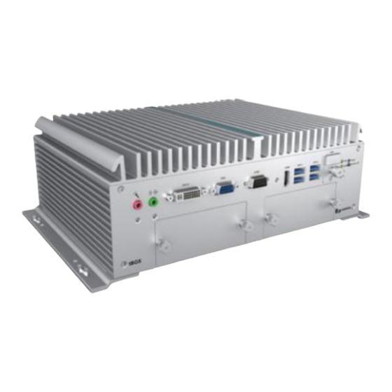
UST500-517-FL Series user’s Manual 1.4 I/O Outlets The following figures show I/O outlets on the UST500-517-FL. Front View UST500-517-FL-16RJ-4SATA-TDC / UST500-517-FL-8RJ8M12-4SATA-TDC Rear View UST500-517-FL-16RJ-4SATA-TDC Introduction... - Page 17 UST500-517-FL Series user’s Manual Rear View UST500-517-FL-8RJ8M12-4SATA-TDC Introduction...
- Page 18 UST500-517-FL Series user’s Manual Front View UST500-517-FL-16RJ-2SATA-TDC / UST500-517-FL-8RJ-2SATA-TDC Rear View UST500-517-FL-16RJ-2SATA-TRAY-TDC Rear View UST500-517-FL-8RJ-2SATA-TRAY-TDC Introduction...
- Page 19 UST500-517-FL Series user’s Manual Front View UST500-517-FL 2SATA-TDC Rear View UST500-517-FL 2SATA-TDC Introduction...
-
Page 20: Packing List
UST500-517-FL Series user’s Manual 1.5 Packing List The UST500-517-FL comes with the following bundle package : 4 SATA Tray No Tray 2 SATA Tray UST500-517-FL system unit x 1 UST500-517-FL system unit x 1 UST500-517-FL system unit x 1 CPU grease x 1... -
Page 21: Model List
(LGA1151), Q170, VGA, DVI-D, HDMI, 6-in/2-out DIO, 2 2SATA-TRAY-TDC COM, 4 USB 3.0,8 RJ-45 PoE GbE LAN, 2 SATA swappable (P/N: E274500105) drives and ACC ignition. Please contact an Axiomtek distributor immediately if any of the abovementioned item is missing. Introduction... - Page 22 UST500-517-FL Series user’s Manual This page is intentionally left blank. Introduction...
-
Page 23: Section 2 Hardware Installation
UST500-517-FL Series user’s Manual SECTION 2 HARDWARE INSTALLATION The UST500-517-FL is convenient for various hardware configurations, such as CPU, DRAM, HDD (Hard Disk Drive), SSD (Solid State Drive), and PCI Express Mini card modules. Section 2 contains guidelines for hardware installation. - Page 24 UST500-517-FL Series user’s Manual Step 4 CPU installation steps: Lift the processor package from shipping media by grasping the substrate edges. Scan the processor package gold pads for any presence of foreign material. Locate connection 1 indicator on the processor which aligns with connection 1 indicator chamfer on the socket, and notice processor keying features that line up with posts along socket walls.
- Page 25 UST500-517-FL Series user’s Manual Step 5 When installing the CPU, pay attention to the CPU’s orientation and align the arrow mark on the CPU with the arrow key on the socket (Step 4).And apply the thermal grease evenly on top of the processor.
-
Page 26: Installing So-Dimm
UST500-517-FL Series user’s Manual 2.2 Installing SO-DIMM Step 1 Turn off the system and unplug the power cord. Step 2 Loosen all screws to remove the top cover. Step 3 Locate the dual SO-DIMM sockets on the main board. Step 4 Insert the gold colored contact of the memory module into the socket and push the module’s two end latches down until locked. -
Page 27: Installing Thermal Pads
UST500-517-FL Series user’s Manual 2.3 Installing thermal pads Step 1 Turn off the system and unplug the power cord. Step 2 Loosen all screws to remove the top cover. Step 3 Put the thermal pads on the secant locations. 【Note】... -
Page 28: Installing 2.5" Sata Device
UST500-517-FL Series user’s Manual 2.4 Installing 2.5” SATA Device 2.4.1 Installing 2.5” SATA Device for 4SATA Step 1 Turn off the system and unplug the power cord. Step 2 Loosen all of the SATA drive tray’s screws. Step 3 Extract the SATA drive tray. Each drive tray can install two storage drives. -
Page 29: Installing 2.5" Sata Device For 2Sata
UST500-517-FL Series user’s Manual Step 5 Slide the secured SATA drive tray back into the system and fasten the screws tight to complete the installation. 2.4.2 Installing 2.5” SATA Device for 2SATA Step 1 Turn off the system and unplug the power cord. -
Page 30: Installing 2.5" Sata Device For No Tray
UST500-517-FL Series user’s Manual Step 4 Turn the SATA drive tray upside down to install SSD/HDD and fasten the four screws to secure the SATA drive tray. Step 5 Slide the secured SATA drive tray back into the system and fasten the screws firmly to complete the installation. - Page 31 UST500-517-FL Series user’s Manual Step 4 Install a HDD/SSD onto a drive holder by tightening HDD/SSD screws on the holder. Step 5 Put the drive holders to precisely meet the screws hole positions and tighten screws. Step 6 Plug the SATA cable into HDD/SSD.
-
Page 32: Installing Mini Pcie Module
UST500-517-FL Series user’s Manual 2.5 Installing Mini PCIe Module 2.5.1 Installing Mini PCIe Module for 4SATA Step 1 Turn off the system and unplug the power cord. Step 2 Turn the system upside down and loosen the SATA tray screws. -
Page 33: Installing Mini Pcie Module For 2Sata
UST500-517-FL Series user’s Manual Step 7 Slide the secured SATA tray back and fasten screws tight to complete the installation. 2.5.2 Installing Mini PCIe Module for 2SATA Step 1 Turn off the system and unplug the power cord. Step 2 Turn the system upside down and loosen the SATA trays. -
Page 34: Installing Mini Pcie Module For No Tray
UST500-517-FL Series user’s Manual Step 6 Secure the cover back to original position and fasten all screws firmly. Step 7 Slide the SATA trays back and fasten screws firmly to complete the installation. 2.5.3 Installing Mini PCIe Module for No Tray Step 1 Turn off the system and unplug the power cord. -
Page 35: Installing 4G/3G Module
UST500-517-FL Series user’s Manual Step 4 Insert the PCIe card and fasten the screws as shown. Step 5 Put the cover back and plug the SATA cable. Step 6 Fasten all cover screws tight to complete the installation. 2.6 Installing 4G/3G Module 2.6.1... - Page 36 UST500-517-FL Series user’s Manual Step 4 Loosen nine bottom cover screws as shown and open the cover carefully. Step 5 Insert the wireless module (3G/4G/BT/GPS module etc.) into the slot with the marking “PCIe / USB”. Step 6 For instance, insert the 3G module and screw it tight.
- Page 37 UST500-517-FL Series user’s Manual Step 9 Put the larger plastic spacer over the other end of the RF cable (Figure 1) (Figure 2), and then insert the end of the RF cable through the antenna hole (Figure 3). (Figure 1)
- Page 38 UST500-517-FL Series user’s Manual Step 11 Put the cover back onto the system, and fasten nine bottom screws tight. Step 12 Slide and secure SATA trays back to complete the installation. Step 13 Turn the system back to its upright position, and screw the RF antenna tight.
-
Page 39: Installing 4G/3G Module For 2Sata
UST500-517-FL Series user’s Manual 2.6.2 Installing 4G/3G Module for 2SATA Step 1 Turn off the system and unplug the power cord. Step 2 Turn the system upside down, and loosen the SATA tray. Step 3 Loosen nine bottom cover screws as shown and open the cover... - Page 40 UST500-517-FL Series user’s Manual Step 4 Insert the wireless module (3G/4G/BT/GPS module etc.) into the slot with the marking “PCIe / USB”. Step 5 For instance, insert the 3G module and screw it tight. Step 6 Remove the black plastic antenna plug cover from the rear panel.
- Page 41 UST500-517-FL Series user’s Manual Step 8 Place the larger plastic spacer over the other end of the RF cable (Figure 1 left) (Figure 2) and then insert the RF cable through the antenna hole (Figure 3). (Figure 1) (Figure 2)
- Page 42 UST500-517-FL Series user’s Manual Step 10 Put the cover back onto the system, and fasten nine bottom screws firmly. Step 11 Slide and secure SATA trays back. Step 12 Place the system upright, and then screw the RF antenna firmly.
-
Page 43: Installing 4G/3G Module For No Tray
UST500-517-FL Series user’s Manual 2.6.3 Installing 4G/3G Module for No Tray Step 1 Turn off the system and unplug the power cord. Step 2 Flip over the system, and loosen the cover screws. Step 3 Open the cover carefully and unplug the SATA cable. - Page 44 UST500-517-FL Series user’s Manual Step 7 Make the end of the RF cable go through the hole of the larger RF gasket . Step 8 Take out the fastening nuts from the 4G/3G kit package (Figure 1). Insert the end of the RF cable through the antenna hole (Figure 2 and 3).
- Page 45 UST500-517-FL Series user’s Manual Step 11 Flip over the system, and screw the RF antenna tight. Step12 Loosen the screw to remove the SIM cover and insert the SIM card. Hardware Installation...
-
Page 46: Installing The Wall Mount Kit
UST500-517-FL Series user’s Manual 2.7 Installing the Wall Mount Kit 2.7.1 Installing the Wall Mount Kit for 2SATA/4SATA Step 1 Turn off the system and unplug the power cord. Step 2 Turn the system upside down to locate four screw holes reserved for the wall mount at the bottom. -
Page 47: Installing The Cable Fixing Plate
UST500-517-FL Series user’s Manual 2.8 Installing the Cable Fixing Plate 2.8.1 Installing the HDMI Cable Fixing Plate Step 1 Turn off the system and unplug the power cord. Step 2 To fasten the HDMI cable fixing plate to the system, position the hole on the plate against the hole on the system, insert the screw into the holes, and turn the screw tightly to fasten the plate, as shown below. - Page 48 UST500-517-FL Series user’s Manual This page is intentionally left blank. Hardware Installation...
-
Page 49: Section 3 Dip Switch, Button & Connector Settings
UST500-517-FL Series user’s Manual SECTION 3 DIP SWITCH, BUTTON & CONNECTOR SETTINGS 3.1 Summary of DIP Switch Settings Proper DIP Switch settings configure the UST500-517-FL to meet various application purposes. The table below lists all jumpers and their default settings. -
Page 50: Buttons
UST500-517-FL Series user’s Manual 3.2 Buttons 3.2.1 Power Button The power button is located on the I/O side. It allows users to control power on/off state of the UST500-517-FL. Functions Descriptions Turn on/off system Keep system status 3.2.2 Reset Button The reset button allows users to reset UST500-517-FL. -
Page 51: Hdmi Connector
UST500-517-FL Series user’s Manual 【 】 Note Connect the DC-in power connector for the UST500-517-FL in-vehicle system as follows: When using in-Vehicle applications, connect the ACC pin to the accessory power of the vehicle. If the testing environment is not able to provide accessory power, refer to the connection method illustrated in Figure 1 to proceed. -
Page 52: Serial Port Connector(Com1~Com2)
UST500-517-FL Series user’s Manual 3.3.5 Serial Port Connector(COM1~COM2) The UST500-517-FL has two serial ports. COM1~COM2 are RS-232/422/485 ports. Please refer to Chapter 4 for detailed BIOS settings. Pins RS-232 RS-422 RS-485 Data- DCD, Data carrier detect Data+ RXD, Receive data... -
Page 53: Usb 3.0 Connector
UST500-517-FL Series user’s Manual NOTE: If PoE power supply exceeds power budget and the PoE LED will start blinking. 3.3.7 USB 3.0 Connector The Universal Serial Bus connectors are compliant with USB 3.0 (5 GB/s), ideal for connecting USB peripherals such as scanners, cameras and other USB devices. Pin definition follows USB Implementers Forum, Inc. -
Page 54: Sata Connector (Sata 1~4)
UST500-517-FL Series user’s Manual 3.3.10 SATA Connector (SATA 1~4) These Serial Advanced Technology Attachment (Serial ATA or SATA) connectors support high- speed SATA interfaces. They are computer bus interfaces for connecting to devices such as hard disk drives. This board has two SATA 3.0 ports with 6Gb/s performance. Pin definition follows Serial ATA International Organization. - Page 55 UST500-517-FL Series user’s Manual UIM_VPP REFCLK+ UIM_RESET REFCLK- UIM_CLK UIM_DATA UIM_PW R 1.5V W AKE# 3.3Vaux Half-Size (CN15 & CN16) CN15 applies to PCI-Express2.0, USB2.0 and SATA (mSATA) signals and complies with PCI- Express Mini Card Spec. V1.2. Thus, users can install an mSATA card into this slot. Please refer to section 3.1 DIP Switch Mode.
- Page 56 UST500-517-FL Series user’s Manual This page is intentionally left blank. Dip Switch, Button & Connector Settings...
-
Page 57: Section 4 Bios Setup Utility
UST500-517-FL Series user’s Manual SECTION 4 BIOS SETUP UTILITY This section provides users with detailed descriptions in terms of how to set up basic system configurations through the BIOS setup utility. 4.1 Starting To enter the setup screens, follow the steps below: Turn on the computer and press the <Del>... -
Page 58: Main Menu
UST500-517-FL Series user’s Manual 4.3 Main Menu The Main Menu screen is the first screen users see when entering the setup utility. Users can always return to the Main setup screen by selecting the Main tab. System Time/Date can be set up as described below. -
Page 59: Advanced Menu
UST500-517-FL Series user’s Manual 4.4 Advanced Menu The Advanced menu also allows users to set configuration of the CPU and other system devices. Users can select any items in the left frame of the screen to go to sub menus: ►... - Page 60 UST500-517-FL Series user’s Manual CPU Configuration This screen shows the CPU version and its detailed information. Intel Virtualization Technology It allows a hardware platform to run multiple operating systems separately and simultaneously, enabling one system to virtually function as several systems.
- Page 61 UST500-517-FL Series user’s Manual NCT6106D Super IO Configuration Use this screen to select options for the NCT6106D Super IO Configurations, and change the value of the selected option. A description of the selected item appears on the right side of the screen.
- Page 62 UST500-517-FL Series user’s Manual Serial Port 1 Configuration Select Mode Use this option to set RS-232/RS-422/RS-485 mode. BIOS Setup Utility...
- Page 63 UST500-517-FL Series user’s Manual Serial Port 2 Configuration BIOS Setup Utility...
- Page 64 UST500-517-FL Series user’s Manual NCT6106D Hardware Monitor This screen displays the temperature of system and CPU and system voltages (VCORE, +3.3V, +12V and +5V). BIOS Setup Utility...
- Page 65 UST500-517-FL Series user’s Manual SATA Configuration SATA Mode Selection AHCI (Advanced Host Controller Interface) mode is how SATA controller(s) operate. Serial ATA Port 0~5 It shows the device installed in connector SATA0~5. BIOS Setup Utility...
- Page 66 UST500-517-FL Series user’s Manual PCH-FW Configuration This screen shows ME Firmware information. BIOS Setup Utility...
- Page 67 UST500-517-FL Series user’s Manual USB Configuration This screen specifies USB settings. USB Devices Display all detected USB devices. BIOS Setup Utility...
- Page 68 BIOS flash utility is a tool for flashing BIOS on setup menu. Follow the steps to flash BIOS. Create a folder and rename it to Axiomtek on the root of USB storage (Ex: X:\Axiomtek) Copy the BIOS file to the Axiomtek folder (Ex: X:\Axiomtek\SBC87517V.103). (Note: The BIOS file name must contain the word SBC87517) Enter the BIOS flash utility and locate the BIOS file.
- Page 69 UST500-517-FL Series user’s Manual BIOS Setup Utility...
- Page 70 UST500-517-FL Series user’s Manual BIOS Setup Utility...
- Page 71 UST500-517-FL Series user’s Manual NCT6106D DIO Configuration Use this screen to display DIO polarity and level. BIOS Setup Utility...
- Page 72 UST500-517-FL Series user’s Manual Ignition Configuration This menu allows users to configure settings related to vehicle ignition switch. Use this screen to set ACC Timer. (1) ACC-ON Delay (T1): Set delay timer for system power on. (2) ACC-OFF Delay (T2): Set delay timer for system power off.
- Page 73 UST500-517-FL Series user’s Manual Advance Setting This item shows all information and voltage settings. Voltage Setting Voltage setting is designed to protec t the lead-acid batteries and keep the system from running out of power when the lead-acid battery is low, so as not to drain the battery.
- Page 74 UST500-517-FL Series user’s Manual Counter Setting (3) Low Voltage Counter: Sets shut down delay time. (4) Very Low Voltage Counter: Sets force turn off system power delay time. Function Spec range Default Value Unit Low Voltage Counter 1~60 Very Low Voltage Counter...
- Page 75 UST500-517-FL Series user’s Manual Save Setting W hen all settings are completed, select “Save Current Setting to PSU” to save changes. If the user forgets to save current settings, the interface will pop up a notice message. BIOS Setup Utility...
- Page 76 UST500-517-FL Series user’s Manual Load Default Setting This option allows you to restore to default settings and save factory defaults. BIOS Setup Utility...
- Page 77 UST500-517-FL Series user’s Manual POE Configuration Power over Ethernet (PoE) describes any of several standard or ad-hoc systems which pass electric power along with data on twisted pair Ethernet cabling. This menu allows users to set the power and enable/disable a specific port.
- Page 78 UST500-517-FL Series user’s Manual Port1~Port8 Enable/Disable a specific POE port and display all port status. Port9~Port16 Enable/Disable a specific POE port and display all port status. BIOS Setup Utility...
-
Page 79: Chipset Menu
UST500-517-FL Series user’s Manual 4.5 Chipset Menu The Chipset menu allows users to change the advanced chipset settings. Users can select any of the items in the left frame of the screen to go to the sub menus: ► System Agent (SA) Configurations For items marked with “”, please press <Enter>... - Page 80 UST500-517-FL Series user’s Manual System Agent (SA) Configurations Graphics Configuration Use this item to configure internal graphics controller. Memory Configuration Use this item to refer to the information related to system memory. BIOS Setup Utility...
- Page 81 UST500-517-FL Series user’s Manual Graphic Configurations Primary IGFX Boot Display Select the video device which will be activated during POST (Power-On Self-Test). The default is Auto. BIOS Setup Utility...
- Page 82 UST500-517-FL Series user’s Manual Memory Configurations This screen shows the system memory information. BIOS Setup Utility...
- Page 83 UST500-517-FL Series user’s Manual Security Menu Administrator Password This item indicates whether an administrator password has been set (installed or uninstalled). User Password This item indicates whether a user password has been set (installed or uninstalled). BIOS Setup Utility...
-
Page 84: Boot Menu
UST500-517-FL Series user’s Manual 4.6 Boot Menu The Boot menu allows users to change boot options of the system. Setup Prompt Timeout Use this item to set up number of seconds to wait for setup activation key where 65535(0xFFFF) means indefinite waiting. -
Page 85: Save & Exit Menu
UST500-517-FL Series user’s Manual 4.7 Save & Exit Menu The Save & Exit menu allows users to load system configurations with optimal or fail-safe default values. Save Changes and Exit When users have completed the system configuration changes, select this option to leave Setup and return to Main Menu. - Page 86 UST500-517-FL Series user’s Manual Save Changes When completed the system configuration changes, select this option to save changes. Select Save Changes from the Save & Exit menu and press <Enter>. Select Yes to save changes. Discard Changes Select this option to quit Setup without making any permanent changes to the system configurations.
-
Page 87: Appendix Awatchdog Timer
How to Use the Watchdog Timer The user can configure the watchdog timer using the watchdog function included in the AXVIEW 2.0 software developed by Axiomtek, or using the debug.exe software released by Microsoft. NOTE: The related tool for setting WDT will not be available on the official downloads area. - Page 88 UST500-517-FL Series user’s Manual Disable watchdog timer STEP Sample code Note 1. Enter configuration mode O 2E 87 Un-lock super I/O O 2E 87 Un-lock super I/O 2. Select logic device O 2E 07 Select logic register O 2F 08 Switch to WDT device 3.
-
Page 89: Appendix Bdigital I/O
UST500-517-FL Series user’s Manual APPENDIX B DIGITAL I/O Digital I/O Specification Digital Input: Input channels: 6, sink/source type Input voltage: 0 to 30VDC Input level for dry contacts: Logic level 0: close to ground Logic level 1: open Input level for wet contacts: Logic level 1: +/-3VDC max. - Page 90 UST500-517-FL Series user’s Manual Digital I/O...
- Page 91 UST500-517-FL Series user’s Manual Digital Input Wiring Digital I/O...
- Page 92 UST500-517-FL Series user’s Manual Digital Output Wiring About Programmable Digital I/O LED UST500-517-FL supports isolated digital I/O which allows the user to control 6DI or 2DO. Please refer to Driver CD for sample code and demo tool to check. 【...
- Page 93 UST500-517-FL Series user’s Manual Digital I/O...
- Page 94 UST500-517-FL Series user’s Manual This page is intentionally left blank. Digital I/O...
-
Page 95: Appendix Cconfiguring Sata For Raid
UST500-517-FL Series user’s Manual APPENDIX C CONFIGURING SATA FOR RAID ® Configuring SATA Hard Drive(s) for RAID (Controller: Intel Q170) Before you begin the SATA configuration, please prepare four SATA hard drives (to ensure optimal performance, it is recommended that you use two hard drives with the identical model and capacity). - Page 96 UST500-517-FL Series user’s Manual Turn on your system, and then press the <Del> button to enter BIOS Setup during running 2.1. POST (Power-On Self-Test). If you want to create RAID, just go to the Advanced Settings menu\SATA Configuration, select the “SATA Mode Selection”, and press <Enter> for more options.
- Page 97 UST500-517-FL Series user’s Manual 3. Configuring RAID by the RAID BIOS. Enter the RAID BIOS setup utility to configure a RAID array. Skip this step and proceed if you do not want to create a RAID. 3.1. After the POST memory testing and before the operating system booting, a message "Press <Ctrl-I>...
- Page 98 UST500-517-FL Series user’s Manual 3.3. After entering the Create Volume Menu screen, you can type the disk array name with 1~16 letters (letters cannot be special characters) in the item “Name:”. 3.4. When finished, press <Enter> to select a RAID level. There are three RAID levels: RAID0, RAID1, RAID5 and RAID10.
- Page 99 UST500-517-FL Series user’s Manual 3.5. Set the stripe block size. The KB is the standard unit of stripe block size. The stripe block size can be 4KB to 128KB. After the setting, press <Enter> for the array capacity. 3.6. After setting all the items on the menu, select Create Volume and press <Enter> to start creating the RAID array.
- Page 100 UST500-517-FL Series user’s Manual 3.7. When prompting the confirmation, press <Y> to create this volume, or <N> to cancel the creation. 3.8. After the creation is completed, you will see detailed information about the RAID array in the Disk/Volume Information section, including RAID mode, disk block size, disk name, disk capacity, etc.
- Page 101 UST500-517-FL Series user’s Manual Delete RAID volume If you want to delete a RAID volume, select the Delete RAID Volume option in Main Menu. Press <Enter> and follow on-screen instructions. Please press <Esc> to exit the RAID BIOS utility. Now, you can proceed to install a SATA driver controller and the operating system.
Need help?
Do you have a question about the UST500-517-FL Series and is the answer not in the manual?
Questions and answers