Table of Contents
Advertisement
Quick Links
Advertisement
Table of Contents

Related Manuals for AXIOMTEK eBOX671-885-FL Series


Summary of Contents for AXIOMTEK eBOX671-885-FL Series
- Page 1 Series Embedded System User’s Manual...
-
Page 2: Disclaimers
Axiomtek does not make any commitment to update the information in this manual. Axiomtek reserves the right to change or revise this document and/or product at any time without notice. No part of this document may be reproduced, stored in a retrieval system, or transmitted, in any form or by any means, electronic, mechanical, photocopying, recording, or otherwise, without the prior written permission of Axiomtek Co., Ltd. -
Page 3: Safety Precautions
Safety Precautions Before getting started, please read the following important safety precautions. The eBOX671-885-FL does not come equipped with an operating system. An operating system must be loaded first before installing any software into the computer. Be sure to ground yourself to prevent static charge when installing the internal components. -
Page 4: Classification
Classification Degree of production against electric shock : not classified Degree of protection against the ingress of water : IP40 Equipment not suitable for use in the presence of a flammable anesthetic mixture with air or with oxygen or nitrous oxide. Mode of operation : Continuous... -
Page 5: General Cleaning Tips
General Cleaning Tips You may need the following precautions before you begin to clean the computer. When you clean any single part or component for the computer, please read and understand the details below fully. When you need to clean the device, please rub it with a piece of dry cloth. Be cautious of the tiny removable components when you use a vacuum cleaner to absorb the dirt on the floor. -
Page 6: Scrap Computer Recycling
If the computer equipment’s needs the maintenance or are beyond repair, we strongly recommended that you should inform your Axiomtek distributor as soon as possible for the suitable solution. For the computers that are no longer useful or no longer working well, please contact your Axiomtek distributor for recycling and we will make the proper arrangement. -
Page 7: Table Of Contents
Table of Contents Disclaimers ......................ii Safety Precautions ....................iii Classification ......................iv General Cleaning Tips ................... v Scrap Computer Recycling ................... vi CHAPTER 1 INTRODUCTION ................1 General Description ................1 System Specifications ............... 3 1.2.1 CPU ........................3 1.2.2 I/O System ...................... - Page 8 3.3.13 Reset Button ....................31 3.3.14 Remote Power Switch Connector (SPWRBT1) ........... 31 3.3.15 AT/ATX Switch ....................32 3.3.16 CFast™ Socket ....................32 3.3.17 SATA Connector (SATA 1 & 2) ..............33 3.3.18 SATA Power Connector ................33 3.3.19 SIM Card Slots ....................33 3.3.20 Full-Size PCI Express Mini Card Slot (SCN2 &...
-
Page 9: Chapter 1 Introduction
Series User’s Manual CHAPTER 1 INTRODUCTION This chapter contains general information and detailed specifications of the eBOX671-885-FL. The Chapter 1 includes the following sections: General Description System Specifications Dimensions I/O Outlets Packing List ... - Page 10 Series User’s Manual Reliable and Stable Design The eBOX671-885-FL adopts the advanced cooling system and supporting the CFast™, & mSATA which makes it especially suitable for vibration environments, eBOX671-885- FL also supports wall mount kit, it’s best for industrial automation, digital signage and gaming application.
-
Page 11: System Specifications
Series User’s Manual System Specifications 1.2.1 CPU LGA1150 Socket Intel® Core™ i7/i5/i3/Celeron processor Chipset Intel® Haswell/ Haswell-refresh Q87 chipset BIOS American Megatrends Inc. UEFI (Unified Extensible Firmware Interface) BIOS. System Memory ... -
Page 12: System Specification
Series User’s Manual Switch: 1 x Power switch 1 x Reset switch 1 x AT/ATX switch 1 x Remote PWR switch connector SIM Slot x 1 1.2.3 System Specification Watchdog Timer ... -
Page 13: Dimensions
Series User’s Manual Dimensions The following diagrams show you dimensions and outlines of the eBOX671-885-FL. 1.3.1 System Dimension Introduction... -
Page 14: Wall Mount Bracket Dimension
Series User’s Manual 1.3.2 Wall mount Bracket Dimension Introduction... -
Page 15: I/O Outlets
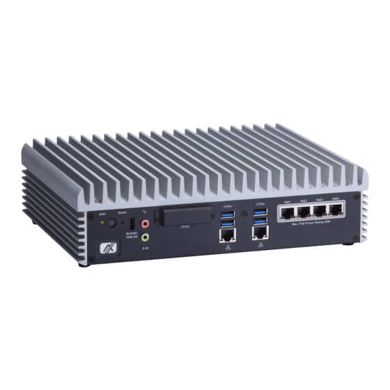
Series User’s Manual I/O Outlets The following figures show you I/O outlets on front view of the eBOX671-885-FL. Front View drawing Introduction... - Page 16 Series User’s Manual Rear View drawing eBOX671-885-FL-DC eBOX671-885-FL-DC-I Introduction...
-
Page 17: Packing List
Fanless Embedded System with Intel Core i7 /i5/i3 & Celeron Processor, Q87 PCH, DVI-I/HDMI/DisplayPort, Dual eBOX671-885-FL-DC-I HDD, PoE*4, GbE LAN*2, USB*8, Audio, COM*4 and 8-CH isolated digital I/O, 24VDC If you cannot find this package or any items are missing, please contact Axiomtek distributors immediately. Introduction... - Page 18 Series User’s Manual This page is intentionally left blank. Introduction...
-
Page 19: Chapter 2 Hardware Installation
Series User’s Manual CHAPTER 2 HARDWARE INSTALLATION The eBOX671-885-FL is convenient for your various hardware configurations, such as Processor, DRAM, HDD (Hard Disk Drive), SSD (Solid State Drive), CFast card or PCI Express Mini Card modules. The chapter 2 will show you how to install the hardware. - Page 20 Series User’s Manual Step 4 Remove the warning label and disengage load lever. Rotate load lever to open position at approximately 135°. Rotate load plate to open position at approximately 150°. Apply pressure to corner with right-hand thumb when opening or...
- Page 21 Series User’s Manual Never touch fragile socket contacts to avoid damage and do not touch processor sensitive contacts at any time during installation. Caution Step 6 Thermal pad installation. Please confirm the processor has placed into CPU socket properly.
- Page 22 Series User’s Manual Step 7 Fasten four screws to assemble top heatsink with main chassis . Hardware Installation...
-
Page 23: Installing The So-Dimm
Series User’s Manual Installing the SO-DIMM Step 1 Turn off the system, and unplug the power cord. Step 2 There are four screws on the top heatsink are used to fasten the heatsink to the chassis. Step 3 Loosen these screws to remove the top heatsink then you can find dual SO-DIMM sockets on main board. - Page 24 Series User’s Manual Step 5 Assemble top heatsink with chassis through four screws carefully to complete SO-DIMM installation. Hardware Installation...
-
Page 25: Installing The 2.5" Sata Device
Series User’s Manual Installing the 2.5” SATA Device Step 1 Turn off the system, and unplug the power cord. Step 2 Turn the system upside down to locate screws at the bottom, loosen screws. Step 3 Remove the bottom cover. - Page 26 Series User’s Manual Step 6 Connect the SATA data cable and SATA power cable to the connectors on the SATA drive. Step 7 Please fasten screws and foot pad to complete installation. Hardware Installation...
-
Page 27: Installing The Express Mini Card
Series User’s Manual Installing the Express Mini Card Step 1 Turn off the system, and unplug the power cord. Step 2 Turn the system upside down to locate screw s at the bottom, loosen screws. Step 3 Remove the bottom cover then find Mini Card location. -
Page 28: Installing The Cfast Card
Series User’s Manual Installing the CFast Card Step 1 Turn off the system, and unplug the power cord. Remove the mounting screws of the CompactFlash socket ’s cover. Step 2 Step 3 Slide CompactFlash card into CompactFlash socket’s slot with caution. -
Page 29: Chapter 3 Jumper Setting & Connector
Series User’s Manual CHAPTER 3 JUMPER SETTING & CONNECTOR Proper jumper settings configure the eBOX671-885-FL to meet your application purpose. We are herewith listing a summary table of all jumpers and default settings for onboard devices, respectively. Jumper & Connector Location SBC87885 Top Side Jumper Setting &... - Page 30 Series User’s Manual SBC87885 Bottom Side Note: We strongly recommended that you should not modify any unmentioned jumper setting without Axiomtek FAE’s instruction. Any modification without instruction might cause system to become damage. Jumper Setting & Connector...
-
Page 31: Jumper Setting Summary
Series User’s Manual Jumper Setting Summary Proper jumper settings configure the eBOX671-885-FL to meet your application purpose. We are herewith listing a summary table of all jumpers and default settings for onboard devices, respectively. Jumper Function/Default Setting Jumper Setting... -
Page 32: Connectors
Series User’s Manual Connectors Connectors connect the board with other parts of the system. Loose or i mproper connection might cause problems. Make sure all connectors are properly and firmly connected. Here is a summary table shows you all connectors and button on the eBOX671-885-FL Series. -
Page 33: Dc-In Phoenix Power Connector
Series User’s Manual 3.3.1 DC-in Phoenix Power Connector The system supports 24V Phoenix DC-in connector for system power input. Signal 3.3.2 HDMI Connector The HDMI (High-Definition Multimedia Interface) is a compact digital interface which is capable of transmitting high-definition video and high-resolution audio over a single cable. -
Page 34: Displayport Connector
Series User’s Manual 3.3.3 DisplayPort Connector DisplayPort interface is also called DP port. Signal Signal DPB_LANE0 DPB_LANE3# DPB_LANE0# Detect Pin DPB_LANE1 DPB_AUX DPB_LANE1# DPB_LANE2 DPB_AUX# DPB_HPDE DPB_LANE2# DPB_LANE3 +3.3V 3.3.4 DVI-I Connector DVI-I ( integrated, combines digital and analog in the same connector; digital may be... -
Page 35: Com1~Com4 Serial Port Connector
Series User’s Manual 3.3.5 COM1~COM4 Serial Port Connector The system has four serial ports. COM1~COM2 are RS-232/422/485 ports. Please refer to Chapter 4 for the detail of BIOS setting. COM3~COM4 are RS-232 ports. ※COM1,COM2 RS-232 RS-422 RS-485 DCD, Data Carrier Detect... -
Page 36: Usb 3.0 Connector
Series User’s Manual 3.3.6 USB 3.0 Connector The Universal Serial Bus connectors are compliant with USB 3.0 (5Gb/s), and ideally for installing USB peripherals such as scanner, camera and USB devices, etc. Signal USB Port 0 Signal USB Port 1... -
Page 37: Usb 2.0 Connector
Series User’s Manual 3.3.8 USB 2.0 Connector The Universal Serial Bus connectors are compliant with USB 2.0 (480Mbps), and ideally for installing USB peripherals such as keyboard, mouse, scanner, etc. Pin Signal USB Port 0 Signal USB Port 1... -
Page 38: Isolated Digital I/O Connector (Option)
Series User’s Manual 3.3.11 Isolated Digital I/O Connector (Option) eBOX671-885-FL also equipped one version that supports isolated COM 8 channel digital I/O to instead of 8 channel programmable digital I/O. Therefore, please refer to the following information if your system belongs to isolated digital I/O version of eBOX671-885-FL. -
Page 39: Atx Power On/Off Button
Series User’s Manual DO Contact Wiring 3.3.12 ATX Power On/OFF Button The ATX power button is on the I/O side. It can allow users to control eBOX671-885- FL power on/off. Function Description Turn on/off system Keep system status 3.3.13 Reset Button The Reset button can allow users to reset eBOX671-885-FL. -
Page 40: At/Atx Switch
Series User’s Manual 3.3.15 AT/ATX Switch You can adjust this switch once you remove CFast cover. If you set AT/ATX switch to AT mode, the system will be automatically power on without pressing soft power button during power input; we can use this switch to achieve auto power on demand. -
Page 41: Sata Connector (Sata 1 & 2)
Series User’s Manual 3.3.17 SATA Connector (SATA 1 & 2) These Serial Advanced Technology Attachment (Serial ATA or SATA) connectors are for high-speed SATA interfaces. They are computer bus interfaces for connecting to devices such as hard disk drives. This board has two SATA 3.0 ports with 6Gb/s performance. -
Page 42: Full-Size Pci Express Mini Card Slot (Scn2 & Scn3)
Series User’s Manual 3.3.20 Full-Size PCI Express Mini Card Slot (SCN2 & SCN3) There are two PCI-Express Mini Card connectors on the bottom side applying to either PCI- Express or USB 2.0 or SATA (mSATA). It complies with PCI-Express Mini Card Spec. V1.2. It can also support mSATA cards. -
Page 43: Chapter 4 Bios Setup Utility
Series User’s Manual CHAPTER 4 BIOS SETUP UTILITY This chapter provides users with detailed description how to set up basic system configuration through the BIOS setup utility. Starting To enter the setup screens, follow the steps below: Turn on the computer and press the <Del> key immediately. -
Page 44: Main Menu
Series User’s Manual Main Menu The first time you enter the setup utility, you will enter the Main setup screen. You can always return to the Main setup screen by selecting the Main tab. System Time/Date can be set up as described below. -
Page 45: Advanced Menu
Series User’s Manual Advanced Menu The Advanced menu also allows users to set configuration of the CPU and other system devices. You can select any of the items in the left frame of the screen to go to the sub menus: ►... - Page 46 Series User’s Manual ACPI Settings You can use this screen to select options for the ACPI configuration, and change the value of the selected option. A description of the selected item appears on the right side of the screen.
- Page 47 Series User’s Manual CPU Configuration This screen shows the CPU information. Hyper-threading To enable hyperthreading you must first enable it in your system's BIOS settings, the default is enabled. Active Processor Cores Active the cores of processors , default sets to “All”.
- Page 48 Series User’s Manual SATA Configuration In this Configuration menu, you can see the currently installed hardware in the SATA ports. During system boot up, the BIOS automatically detects the presence of SATA devices. SATA Mode Selection Determine how SATA controller(s) operate. Operation mode options are RAID Mode, IDE Mode and AHCI Mode.
- Page 49 Series User’s Manual NCT6106D Super IO Configuration You can use this screen to select options for the Super IO Configuration, and change the value of the selected option. A description of the selected item appears on the right side of the screen. For items marked with “”, please press <Enter>...
- Page 50 Series User’s Manual Serial Port 1 Configuration Serial Port Use this item to enable or disable serial port 1. The optimal setting for base I/O address is 3F8h and for interrupt request line is IRQ4. Select Mode Use this item to configure serial port 1. Here are the options for your selection:...
- Page 51 Series User’s Manual Serial Port 2 Configuration Serial Port Use this item to enable or disable serial port 2. The optimal setting for base I/O address is 2F8h and for interrupt request line is IRQ3. Select Mode Use this item to configure serial port 2. Here are the options for your selection:...
- Page 52 Series User’s Manual Serial Port 3 Configuration Serial Port Use this item to enable or disable serial port 3. The optimal setting for base I/O address is 3E8h and for interrupt request line is IRQ7. BIOS Setup Utility...
- Page 53 Series User’s Manual Serial Port 4 Configuration Serial Port Use this item to enable or disable serial port 4. The optimal setting for base I/O address is 2E8h and for interrupt request line is IRQ6. BIOS Setup Utility...
- Page 54 Series User’s Manual NCT6106D HW Monitor Users can base on this page to get detail hardware monitor information. Intel I211 Gigabit Network Connection setting (Port1 to Port 6) Port Configuration Menu User’s can get LAN detail connection information by this page.
-
Page 55: Chipset Menu
Series User’s Manual Chipset Menu The Chipset menu allows users to change the advanced chipset settings. You can select any of the items in the left frame of the screen to go to the sub menus: ► PCH-IO Configuration ►... - Page 56 Series User’s Manual PCH-IO Configuration This screen shows memory information. For items marked with “”, please press <Enter> for more options. PCH Azalia Configuration This item controls detection of the Azalia device. BIOS Setup Utility...
- Page 57 Series User’s Manual System Agent (SA) Configuration This screen provides function for specifying internal graphics controller and memory related parameters. Graphics Configuration Primary IGFX Boot Display Select the video device which will be activated during POST (Power-On Self Test).
- Page 58 Series User’s Manual DVMT Pre-Allocated Dynamic video memory technology (DVMT) allows dynamic allocation of system memory for use as video memory to ensure the most efficient use of available resources for maximum 2D/3D graphics performance. DVMT Total Gfx Mem Select DVMT 5.0 total graphics memory size used by the internal graphics device.
-
Page 59: Boot Menu
Series User’s Manual Boot Menu The Boot menu allows users to change boot options of the system. Setup Prompt Timeout Number of seconds to wait for setup activation key. 65535(0xFFFF) means indefinite waiting. Bootup NumLock State Select the keyboard NumLock state. -
Page 60: Security Menu
Series User’s Manual Security Menu The Security menu allows users to change the security settings for the system. Administrator Password This item indicates whether an administrator password has been set (installed or uninstalled). User Password This item indicates whether an user password has been set (installed or uninstalled). -
Page 61: Save & Exit Menu
Series User’s Manual Save & Exit Menu The Save & Exit menu allows users to load your system configuration with optimal or fail-safe default values. Save Changes and Exit When you have completed the system configuration changes, select this option to leave Setup and return to Main Menu. - Page 62 Series User’s Manual Save Changes When you have completed the system configuration changes, select this option to save changes. Select Save Changes from the Save & Exit menu and press <Enter>. Select Yes to save changes. Discard Changes Select this option to quit Setup without making any permanent changes to the system configuration.
-
Page 63: Appendix Awatchdog Timer
Series User’s Manual APPENDIX A WATCHDOG TIMER About Watchdog Timer Software stability is major issue in most application. Some embedded systems are not watched by human for 24 hours. It is usually too slow to wait for someone to reboot when computer hangs. -
Page 64: Sample Program
Series User’s Manual Sample Program The following example enables configuration using debug tool. Enable WDT Enable configuration: O 2E 87 ; Un-lock super I/O O 2E 87 Select logic device: O 2E 07 O 2F 08 ...
Need help?
Do you have a question about the eBOX671-885-FL Series and is the answer not in the manual?
Questions and answers