
Related Manuals for AXIOMTEK IPC964-512-FL Series


Summary of Contents for AXIOMTEK IPC964-512-FL Series
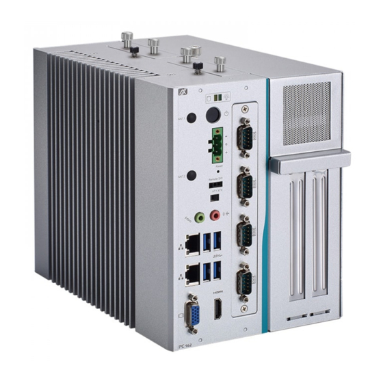
- Page 1 IPC962-511-FL series IPC964-512-FL Series Industrial and Fanless Computers User’s Manual...
- Page 2 Axiomtek does not make any commitment to update the information in this manual. Axiomtek reserves the right to change or revise this document and/or product at any time without notice.
-
Page 3: Safety Precautions
Safety Precautions Before getting started, please read the following important safety precautions. The IPC962-511-FL/IPC964-512-FL Series does not come equipped with an operating system. An operating system must be loaded first before installing any software into the com puter. Be sure to ground yourself to prevent static charge when installing the internal components. -
Page 4: Classification
Classification Degree of production against electric shock: not classified Degree of protection against the ingress of water: IPX40 Equipment not suitable for use in the presence of a flammable anesthetic mixture with air or with oxygen or nitrous oxide. Mode of operation: Continuous Type of protection against electric shock: Class I equipment General Cleaning Tips You may need the following precautions before you begin to clean the computer. - Page 5 Cleaning Tools: Although many companies have created products t o help improve the process of cleaning your computer and peripherals users can also use household items to clean their computers and peripherals. Below is a listing of items you may need or want to use while cleaning your computer or computer peripherals.
-
Page 6: Scrap Computer Recycling
If the computer equipments need the maintenance or are beyond repair, we strongly recommended that you should inform your Axiomtek distributor as soon as possible for the suitable solution. For the computers that are no longer useful or no longer working well, please contact your Axiomtek distributor for recycling and we will make the proper arrangement. -
Page 7: Table Of Contents
Table of Contents Safety Precautions ....................iii Classification ......................iv General Cleaning Tips ..................iv Scrap Computer Recycling .................. vi CHAPTER 1 INTRODUCTION ................1 General Description ................1 System Specifications ............... 2 1.2.1 Main CPU Board ....................2 1.2.2 I/O System ...................... - Page 8 Security Menu .................. 47 Boot Menu ..................48 Save & Exit Menu ................49 APPENDIX A WATCHDOG TIMER ..............51 About Watchdog Timer ..............51 How to Use Watchdog Timer ............51 Sample Program ................53 viii...
-
Page 9: Chapter 1 Introduction
I/O Outlets Jumper Settings Connectors Package List General Description The IPC962-511-FL/IPC964-512-FL Series is a fanless system that can support ® LGA1151 socket for Intel generation Core i7/i5/i3 processors. The IPC962- ® ® 511-FL/IPC964-512-FL Series supports W indows... -
Page 10: System Specifications
IPC962-511-FL/IPC964-512-FL Series User’s Manual System Specifications 1.2.1 Main CPU Board ® Socket LGA1151 for 6 Generation Intel Core i7/i5/i3 processors, up to 35W System Chipset ® Intel H110 chipset (IPC962-511) ® Intel Q170 chipset (IPC964-512) ... -
Page 11: System Specification
(120W) Note: 12V maximum loading 10A , the remaining 30W is shared by 3.3V & 5V. Note: 24V is only for Axiomtek’s add-on card. 1.2.3 System Specification Drive Capacity Supports two 2.5” HDD driver bay (SSD/HDD thickness<=15mm) Note: Due to Gen. 2 SSD with JMicron controller has compatibility issue with Intel H110 PCH, we strongly recommend to use Gen. - Page 12 IPC962-511-FL/IPC964-512-FL Series User’s Manual Note: All specifications and images are subject to change without notice. The performance of the system might be adversely affected a t an °C. operatingtemperature above 60 Note: If the operating temperature is above 35 ° C, it is recommended to use a wide temperature SSD on the device.
-
Page 13: Dimensions
IPC962-511-FL/IPC964-512-FL Series User’s Manual Dimensions The following diagrams show you dimensions and outlines of the IPC962-511-FL/IPC964-512- FL Series. IPC962-511 IPC964-512 Introduction... -
Page 14: I/O Outlets
IPC962-511-FL/IPC964-512-FL Series User’s Manual I/O Outlets The following figures show you I/O outlets on front and rear panels of the IPC962-511- FL/IPC964-512-FL Series. IPC962-511 Front Panel Introduction... - Page 15 IPC962-511-FL/IPC964-512-FL Series User’s Manual IPC964-512 Front Panel Introduction...
-
Page 16: Packing List
Foot pad x 4 CPU grease x 1 Terminal block x 1 Remote switch cable x 1 Holder bracket x1 If you can not find this package or any items are missing, please contact Axiomtek distributors immediately. Introduction... -
Page 17: Jumper Settings
IPC962-511-FL/IPC964-512-FL Series User’s Manual Jumper Settings Properly configure jumper settings on the SBC87511/SBC87512 to meet your application purpose. Below you can find a summary table of all jumpers and onboard default settings. Note: How to setup Jumpers That a cap on a jumper is to “close” the jumper, whereas that offs a jumper is to “open” the jumper. -
Page 18: Connectors
IPC962-511-FL/IPC964-512-FL Series User’s Manual Connectors Connectors connect this board with other parts of the system. Loose or improper connection might cause problems. Make sure all connectors are properly and firmly connected. Here is a summary table shows you all connectors on the board. -
Page 19: Mini Card Slot (Cn3)
IPC962-511-FL/IPC964-512-FL Series User’s Manual 1.7.1 MINI CARD SLOT (CN3) There is a PCI-Express Mini Card connector on the top side applying USB 2.0. It supports an USB mini card. Pins Signals Pins Signals W AKE# +3.3VSB No use No use +1.5V... -
Page 20: Lan+Usb3.0 (Cn4、Cn5)
IPC962-511-FL/IPC964-512-FL Series User’s Manual 1.7.2 LAN+USB3.0 (CN4、CN5) The system has two RJ-45 connectors: LAN1 and LAN2. Ethernet connection can be established by plugging one end of the Ethernet cable into this RJ-45 connector and the other end (phone jack) to a 1000/100/10-Base-T hub. -
Page 21: Vga Connector (Cn6)
IPC962-511-FL/IPC964-512-FL Series User’s Manual The Universal Serial Bus connectors are compliant with USB 3.0 (5Gb/s), and ideally for installing USB peripherals such as scanner, camera and USB devices, etc. Pins Signal USB Port 0 Pins Signal USB Port 1 USB_VCC (+5V level standby... -
Page 22: Audio Connector (Cn7)
IPC962-511-FL/IPC964-512-FL Series User’s Manual 1.7.4 Audio Connector (CN7) These two audio jacks ideal are for Audio Mic-In and Audio Line-out. Pins Signals Line Out Microphone In 1.7.5 DC-in Phoenix Power Connector (CN8) The system supports 24VDC (uMin=19V/uMax=30V) Phoenix DC-in connector for system power input. -
Page 23: Sata Power Connector (Scn1、Scn2)
IPC962-511-FL/IPC964-512-FL Series User’s Manual 1.7.7 SATA Power connector (SCN1、SCN2) Use SCN1、SCN2 for interfacing to SATA 2.5" HDD power supply. Pins Signals +12V level +5V level 1.7.8 SATA Connector (SATA1、SATA2) These Serial Advanced Technology Attachment (Serial ATA or SATA) connectors are for high-speed SATA interfaces. -
Page 24: At/Atx Switch (Sw2)
IPC962-511-FL/IPC964-512-FL Series User’s Manual 1.7.10 AT/ATX Switch (SW2) If you set AT/ATX switch to AT mode, the system will be automatically power on without pressing soft power button during power input; we can use this switch to achieve auto power on demand. -
Page 25: Flexible Io - Com I/O Card Connector (Ax93511)
IPC962-511-FL/IPC964-512-FL Series User’s Manual 1.7.13 Flexible IO - COM I/O Card Connector (AX93511) The system has four serial ports. COM1~COM4 are RS-232/422/485 ports. Please refer to Chapter 4 for the detail of BIOS setting. ※COM1,COM2,COM3,COM4 Pins RS-232 RS-422 RS-485 DCD, Data Carrier Detect... - Page 26 IPC962-511-FL/IPC964-512-FL Series User’s Manual This page is intentionally left blank. Introduction...
-
Page 27: Chapter 2 Hardware Installation
CHAPTER 2 HARDWARE INSTALLATION The IPC962-511-FL/IPC964-512-FL Series are convenient for your various hardware configurations, such as CPU (Central Processing Unit), Memory Module, HDD (Hard Disk Drive) and PCIe/PCI card. The chapter 2 will show you how to install the hardware. It includes: Installing the Processor The Intel®... - Page 28 IPC962-511-FL/IPC964-512-FL Series User’s Manual Procedure of Installation: Step 1 Turn off the system. Step 2 Disconnect the power connector. Step 3 Loosen screws to remove the Heatsink cover from the chassis. Step 4 After opening the HS cover, you can locate the CPU socket as marked. Align pins of the CPU with pin holes of the socket.
-
Page 29: Installing The Memory Module
IPC962-511-FL/IPC964-512-FL Series User’s Manual Step 5 Then, applying thermal grease on top of the CPU Step 6 After install all components, please close the HS cover back to the chassis and fasten all screws. Installing the Memory Module Step 1 Turn off the system. - Page 30 IPC962-511-FL/IPC964-512-FL Series User’s Manual Step 4 Install the memory module into the socket and push it firmly down until it is fully seated. The socket latches are clipped on to the edges of the SO-DIMM. Step 5 After install the ram modules, please close the Heatsink cover back to the chassis and fasten all screws.
-
Page 31: Installing The Hard Disk Drive
IPC962-511-FL/IPC964-512-FL Series User’s Manual Installing the Hard Disk Drive The IPC962-511-FL/IPC964-512-FL Series offers a convenient drive bay module for users to install HDD. The system offers users two 2.5” Hard Disk Drive for installation. Please follow the steps: Step 1 Turn off the system. -
Page 32: Installing The Fan Module And Pci Or Pcie Card
IPC962-511-FL/IPC964-512-FL Series User’s Manual Installing the Fan Module and PCI or PCIe Card IPC962-511-FL/IPC964-512-FL provides two/four PCI or PCIe slots for expansion. The procedure of installing the Fand module and PCI / PCIe expansion card into IPC962-511- FL/IPC964-512-FL is instructed below. - Page 33 IPC962-511-FL/IPC964-512-FL Series User’s Manual Step 5 Locate the PCI or PCIe slots and remove the slot bracket which you want to add the card in. Step 6 Align the PCI or PCIe card with the slot, press the card into the slot until it is firmly seated and screw it.
- Page 34 IPC962-511-FL/IPC964-512-FL Series User’s Manual Step 8 Close the cover back to the chassis and fasten all screws. Installing the WIFI Module The IPC962-511 and IPC964-512 come with a Mini card slo (for IPC964-512) and an USB connector for users to install a wireless LAN card. Please refer to the following instructions and illustrationfor the installation of the wireless LAN.
- Page 35 IPC962-511-FL/IPC964-512-FL Series User’s Manual Step 4 Insert the wireless LAN card to slot. Push it down firmly. Then screw tightly the card to the mainboard Step 5 Remove the antenna plug from the top of back cover, and then install the antenna on the antenna connector.
- Page 36 IPC962-511-FL/IPC964-512-FL Series User’s Manual Installing the WIFI Module via USB Step 1 Turn off the system. Step 2 Disconnect the power connector. Step 3 Loosen screws to remove the Heatsink cover from the chassis. Step 4 Remove the antenna plug from the top of back cover, and then install the...
- Page 37 IPC962-511-FL/IPC964-512-FL Series User’s Manual Step 6 Connect the antenna to wifi module via the bottom of main board. Step 7 Connect USB cable to wifi module. Step 8 Stick wifi module on chassis. Locate the antenna cable and connect it to the wireless LAN card, then connect the USB cable to USB connector.
- Page 38 IPC962-511-FL/IPC964-512-FL Series User’s Manual This page is intentionally left blank. Hardware Installation...
-
Page 39: Chapter 3 Ami Bios Utility
IPC962-511-FL/IPC964-512-FL Series User’s Manual CHAPTER 3 AMI BIOS UTILITY The AMI UEFI BIOS provides users with a built-in setup program to modify basic system configuration. All configured parameters are stored in a 16MB flash chip to save the setup information whenever the power is turned off. This chapter provides users with detailed description about how to set up basic system configuration through the AMI BIOS setup utility. -
Page 40: Navigation Keys
IPC962-511-FL/IPC964-512-FL Series User’s Manual Navigation Keys The BIOS setup/utility uses a key-based navigation system called hot keys. Most of the BIOS setup utility hot keys can be used at any time during the setup navigation process. These keys include <F1>, <F2>, <Enter>, <ESC>, <Arrow> keys, and so on. -
Page 41: Main Menu
IPC962-511-FL/IPC964-512-FL Series User’s Manual Main Menu The first time you enter the setup utility, you will be in the Main setup screen. You can always return to the Main setup screen by selecting the Main tab. System Time/Date can be set up as described below. -
Page 42: Advanced Menu
IPC962-511-FL/IPC964-512-FL Series User’s Manual Advanced Menu Launch PXE OpROM Use this item to enable or disable the boot ROM function of the onboard LAN chip when the system boots up. The Advanced menu also allows users to set configuration of the CPU and other system devices. - Page 43 IPC962-511-FL/IPC964-512-FL Series User’s Manual HW Monitor This screen monitors hardware health. AMI BIOS Utility...
- Page 44 IPC962-511-FL/IPC964-512-FL Series User’s Manual ACPI Settings ACPI configuration can be configured in ACPI Settings. A description of the selected item appears on the right side of the screen. ACPI Sleep State Select the highest ACPI sleep state the system will enter when the suspend button is pressed.
- Page 45 IPC962-511-FL/IPC964-512-FL Series User’s Manual CPU Configuration This screen shows the CPU Configuration, and you can change the value of the selected option. Intel Virtualization Technology This item allows a hardware platform to run multiple operating systems separately and simultaneously, enabling one system to virtually function as several systems.
- Page 46 IPC962-511-FL/IPC964-512-FL Series User’s Manual SATA Configuration You can read the current installed hardware configurations from those SATA ports in the SATA Configuration menu. During system boot up, BIOS will detect the present SATA devices automatically. AMI BIOS Utility...
- Page 47 IPC962-511-FL/IPC964-512-FL Series User’s Manual FCH-FW Configuation Display ME firmware information AMI BIOS Utility...
- Page 48 IPC962-511-FL/IPC964-512-FL Series User’s Manual USB Configuration USB configuration can be configured here by selecting and changing each item. A description of the selected item appears on the right side of the screen. USB Devices Display all detected USB devices.
- Page 49 IPC962-511-FL/IPC964-512-FL Series User’s Manual Module Configuration Serial Port 1~4 Configuration Use this item to set parameters of serial port 1 to 4. AMI BIOS Utility...
- Page 50 IPC962-511-FL/IPC964-512-FL Series User’s Manual Serial Port (1~4) Configuration COM Port Type Use this item to set parameters of RS232/422/485. AMI BIOS Utility...
-
Page 51: Chipset Menu
IPC962-511-FL/IPC964-512-FL Series User’s Manual Chipset Menu The Chipset menu allows users to change the advanced chipset settings. You can select any of the items in the left frame of the screen to go to the sub menus: ► System Agent (SA) Configuration For items marked with “”, please press <Enter>... - Page 52 IPC962-511-FL/IPC964-512-FL Series User’s Manual System Agent (SA) Configuration This screen shows System Agent information and provides function for specifying related parameters. For items marked with “”, please press <Enter> for more options. Graphics Configuration Use this item for graphics configuration settings.
- Page 53 IPC962-511-FL/IPC964-512-FL Series User’s Manual Graphic Configuration Displat Select Allow you to select which graphics controller to use as the primary boot device. AMI BIOS Utility...
- Page 54 IPC962-511-FL/IPC964-512-FL Series User’s Manual Memory Configuration AMI BIOS Utility...
-
Page 55: Security Menu
IPC962-511-FL/IPC964-512-FL Series User’s Manual Security Menu The Security menu allows users to change the security settings for the system. Administrator Password This item indicates whether an administrator password has been set (installed or uninstalled). User Password This item indicates whether an user password has been set (installed or uninstalled). -
Page 56: Boot Menu
IPC962-511-FL/IPC964-512-FL Series User’s Manual Boot Menu The Boot menu allows users to change boot options of the system. Setup Prompt Timeout Number of seconds to wait for setup activation key. 65535(0xFFFF) means indefinite waiting. Bootup NumLock State Use this item to select the power-on state for the keyboard NumLock. -
Page 57: Save & Exit Menu
IPC962-511-FL/IPC964-512-FL Series User’s Manual Save & Exit Menu The Save & Exit menu allows users to load your system configuration with optimal or fail-safe default values. Save Changes and Exit When finish the system configuration settings, select this option to leave Setup and return to Main Menu. - Page 58 IPC962-511-FL/IPC964-512-FL Series User’s Manual Discard Changes and Reset Select this option to quit Setup without making any permanent changes to the system configuration and reboot the computer. Select Discard Changes and Reset from the Save & Exit menu and press <Enter>. Select Yes to discard changes and reset.
-
Page 59: Appendix Awatchdog Timer
IPC962-511-FL/IPC964-512-FL Series User’s Manual APPENDIX A WATCHDOG TIMER A.1 About Watchdog Timer Software stability is major issue in most application. Some embedded systems are not watched by operator for 24 hours. It is usually too slow to wait for someone to reboot when computer hangs. - Page 60 IPC962-511-FL/IPC964-512-FL Series User’s Manual Begin Begin Next Next Enable and Initialize Enable and Initialize Watchdog Timer Watchdog Timer Next Next Program “A” Program “A” Next Next Disable Watchdog Reset Watchdog Timer Timer Next Next Watchdog Timer...
-
Page 61: Sample Program
IPC962-511-FL/IPC964-512-FL Series User’s Manual A.3 Sample Program Assembly sample code : ;Enable WDT: dx,2Eh al,87 ;Un-lock super I/O dx,al dx,al ;Select Logic device: dx,2Eh al,07h dx,al dx,2Fh al,07h dx,al ;Enable WDT base address: dx,2Eh al,30h dx,al dx,2Fh al,01h dx,al ;Activate WDT:... - Page 62 IPC962-511-FL/IPC964-512-FL Series User’s Manual al,0F6h dx,al dx,2Fh al,Mh ;M=00h,01h,...FFh (hex),Value=0 to 255 Note dx,al ;(see below) ;Set Second or Minute : dx,2Eh al,0F5h dx,al dx,2Fh Note al,Nh ;N=71h or 79h(see below) dx,al Note: If N=71h, the time base is set to second.
- Page 63 IPC962-511-FL/IPC964-512-FL Series User’s Manual If N=79h, the time base is set to minute. M = time value 00: Time-out disable 01: Time-out occurs after 1 minute 02: Time-out occurs after 2 minutes 03: Time-out occurs after 3 minutes FFh: Time-out occurs after 255 minutes...
Need help?
Do you have a question about the IPC964-512-FL Series and is the answer not in the manual?
Questions and answers