Table of Contents
Advertisement
Quick Links
Advertisement
Table of Contents

Related Manuals for AXIOMTEK eBOX800-511-FL Series


Summary of Contents for AXIOMTEK eBOX800-511-FL Series
- Page 1 Series Embedded System User’s Manual...
-
Page 2: Disclaimers
Axiomtek does not make any commitment to update any information in this manual. Axiomtek reserves the right to change or revise this document and/or product at any time without notice. No part of this document may be reproduced, stored in a retrieval system, or transmitted in any forms or by any means, electronic, mechanical, photocopying, recording, among others, without prior written permissions of Axiomtek Co., Ltd. -
Page 3: Safety Precautions
Safety Precautions Before getting started, please read the following important safety precautions. The eBOX800-511-FL does not come with an operating system which must be loaded first before installation of any software into the computer. Be sure to ground yourself to prevent static charge when installing any internal components. -
Page 4: Classifications
Classifications Degree of production against electric shock: not classified Degree of protection against ingress of water: IP67 Equipment not suitable for use in the presence of a flammable anesthetic mixture with air, oxygen or nitrous oxide. Mode of operation: Continuous... -
Page 5: General Cleaning Tips
General Cleaning Tips Please keep the following precautions in mind while understanding the details fully before and during any cleaning of the computer and any components within. A piece of dry cloth is ideal to clean the device. Be cautious of any tiny removable components when using a vacuum cleaner to absorb dirt on the floor. -
Page 6: Scrap Computer Recycling
Scrap Computer Recycling Please inform the nearest Axiomtek distributor as soon as possible for suitable solutions in case computers require maintenance or repair; or for recycling in case computers are out of order. Trademarks Acknowledgments Axiomtek is a trademark of Axiomtek Co., Ltd. -
Page 7: Table Of Contents
Table of Contents Disclaimers ......................ii Safety Precautions ....................iii Classifications ....................... iv General Cleaning Tips ................... v Scrap Computer Recycling ................... vi SECTION 1 INTRODUCTION ................ 1 General Descriptions ................. 1 System Specifications ............... 3 1.2.1 CPU ........................3 1.2.2 I/O System ...................... - Page 8 SECTION 4 BIOS SETUP UTILITY .............. 33 Starting ..................... 33 Navigation Keys ................33 Main Menu ..................34 Advanced Menu ................35 Chipset Menu ................... 47 Boot Menu ..................53 Save & Exit Menu ................54 APPENDIX A WATCHDOG TIMER .............. 57 About Watchdog Timer ..............
-
Page 9: Section 1 Introduction
eBOX800-511-FL-FL Series user’s Manual SECTION 1 INTRODUCTION This section contains general information and detailed specifications of the eBOX800-511-FL.Section 1 consist of the following sub-sections: General Descriptions System Specifications Dimensions I/O Outlets Packing List Model List 1.1 General Descriptions ®... - Page 10 eBOX800-511-FL-FL Series user’s Manual Reliable and Stable Design Powered by onboard quad-core processor, the eBOX800-511-FL is equipped with M12 lockable connectors while supporting wall-mount/vest-mount kit for outdoor applications. Flexible Connectivity The eBOX800-511-FL features one Gigabit Ethernet ports and two USB 2.0 ports. Additionally, it also supports two RS-232/422/485 serial interfaces.
-
Page 11: System Specifications
eBOX800-511-FL-FL Series user’s Manual 1.2 System Specifications 1.2.1 CPU ® Core™ i5-7300U 2.6 GHz Intel ® ® Intel Celeron 3965U 2.2 GHz Chipset SoC integrated BIOS American Megatrends Inc. UEFI (Unified Extensible Firmware Inte rface) BIOS System Memory ... -
Page 12: System Specifications
eBOX800-511-FL-FL Series user’s Manual 1.2.3 System Specifications Watchdog Timer 1~255 seconds or minutes; up to 255 levels. Power Supply 9~36 VDC input Operation Temperature -30℃ ~ 60℃ (-22 ºF ~ 140ºF), with W.T. SSD & Memory) Storage Temperature ... -
Page 13: Dimensions
eBOX800-511-FL-FL Series user’s Manual 1.3 Dimensions The following diagrams show dimensions and outlines of the eBOX800-511-FL. 1.3.1 System Dimensions Introduction... -
Page 14: Wall-Mount Bracket Dimensions
eBOX800-511-FL-FL Series user’s Manual 1.3.2 Wall-mount Bracket Dimensions Introduction... -
Page 15: Vesa-Mount Bracket Dimensions
eBOX800-511-FL-FL Series user’s Manual 1.3.3 VESA-mount Bracket Dimensions Introduction... -
Page 16: I/O Outlets
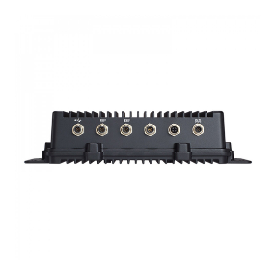
eBOX800-511-FL-FL Series user’s Manual 1.4 I/O Outlets The following figures show I/O outlets on front of the eBOX800-511-FL. Top View Bottom View Introduction... -
Page 17: Packing List
® Rugged IP67-rated fanless embedded system with Intel ® eBOX800-511-FL- DC-3965U Celeron 3965U 2.2 GHz, VGA, 1 GbE LANs, 2 USBs, 2 COMs and 9~36VDC power input Please contact Axiomtek’s distributors immediately in case any abovementioned items are missing. Introduction... - Page 18 eBOX800-511-FL-FL Series user’s Manual This page is intentionally left blank. Introduction...
-
Page 19: Section 2 Hardware Installation
【Note】: Waterproof capability may be affected if a system is dissembled; under such circumstances Axiomtek shall not be liable for any quality deterioration. 【Note】: Please refer to tightening torque below for all system screws: HEX socket set screw: 7.5 kgf HEX KEY specifications are shown below ... -
Page 20: Installation Of 2.5" Sata Device
eBOX800-511-FL-FL Series user’s Manual 2.1 Installation of 2.5" SATA Device Step 1 Turn off the system and unplug the power cord. Step 2 Turn the system upside down to locate screws at the bottom and then loosen all screws. Step 3 Remove the bottom cover. - Page 21 eBOX800-511-FL-FL Series user’s Manual Step 5 Before install an SSD/HDD, please place the mylar on top of the SSD/HDD and fasten two screws. Step 6 Install the SSD/HDD into the HDD drive bay and push the poron down to ensure the complete insertion of SSD/HDD. Hardware Installation...
-
Page 22: Installation Of So-Dimm
eBOX800-511-FL-FL Series user’s Manual 2.2 Installation of SO-DIMM Step 1 Turn off the system and unplug the power cord. Step 2 Six screws on the bottom heatsink are used to fasten the heatsink to the chassis. Step 3 Loosen the thumb screws to remove the metal plate then a SO-DIMM socket on main board is visible. - Page 23 eBOX800-511-FL-FL Series user’s Manual Step 4 Locate the memory module, insert a gold colored contact into the socket and push the module two end latches till locked. Step 5 Replace the metal plate, fasten the thumb screws, then put the bottom cover and fasten six screws back onto the system.
-
Page 24: Installation Of Wi-Fi Mini Pcie Module (Half-Size)
eBOX800-511-FL-FL Series user’s Manual 2.3 Installation of WI-FI Mini PCIe Module (half-size) Step 1 Turn off the system and unplug the power cord. Step 2 Turn the system upside down to locate screws at the bottom, and then loosen all screws. Step 3 Remove the metal plate by loosening the thumb screw, identify the WI- FI, and then insert a WI-FI module. -
Page 25: Installation Of 3G/4G Mini Pcie Module (Full-Size)
eBOX800-511-FL-FL Series user’s Manual 2.4 Installation of 3G/4G Mini PCIe Module (full-size) Step 1 Turn off the system and unplug the power cord. Step 2 Turn the system upside down to locate screws at the bottom, and then loosen all screws. Step 3 Remove the metal plate by loosening the thumb screw s, identify the socket,and then insert a 3G/4G module. - Page 26 eBOX800-511-FL-FL Series user’s Manual Step 4 Connect RF cable to I-PEX4 connector of 3G/4G Module and install Antenna 3 and Antenna 4. Hardware Installation...
-
Page 27: Section 3 Jumper & Connector Settings
eBOX800-511-FL-FL Series user’s Manual SECTION 3 JUMPER & CONNECTOR SETTINGS Proper jumper settings configure the eBOX800-511-FL to meet various application needs. Hereby all jumpers settings along with their default settings are listed for devices onboard. 3.1 Locations of Jumpers & Connectors PICO511 Top View Jumper &... - Page 28 Series user’s Manual PICO511 Bottom View 【 Note 】 : It is strongly recommended that any unmentioned jumper settings should not be modified without instructions by Axiomtek FAEs. Any modifications without instructions might cause system failure. Jumper & Connector Settings...
-
Page 29: Summary Of Jumper Settings
eBOX800-511-FL-FL Series user’s Manual 3.2 Summary of Jumper Settings Proper jumper settings configure the eBOX800-511-FL to meet various application purposes. A table of all jumpers and their default settings is listed below. PICO511 Jumpers Descriptions Settings Restore BIOS Optimal Defaults 1-2 Close Default: Normal Operation Auto Power On... -
Page 30: Restore Bios Optimal Defaults (Jp2)
eBOX800-511-FL-FL Series user’s Manual 3.2.1 Restore BIOS Optimal Defaults (JP2) Put jumper clip to pin 2-3 for a few seconds then move it back to pin 1-2. Doing this procedure can restore BIOS optimal defaults. Function Setting Normal (Default) 1-2 close Restore BIOS optimal defaults 2-3 close 3.2.2 Auto Power On (JP3) -
Page 31: Connectors
eBOX800-511-FL-FL Series user’s Manual 3.3 Connectors Please refer to pin assignments below : External Connectors Sections Serial Port 3.3.1 Ethernet Port 3.3.2 USB Port 3.3.3 DC Power Jack Connector 3.3.4 VGA Connector 3.3.5 Internal Connectors Sections Half-size PCI-Express Mini Card (on PICO511) 3.3.6 Full-size PCI-Express Mini Card or mSATA 3.3.7... -
Page 32: Serial Port (M12 A-Code 8 Pos Male)
eBOX800-511-FL-FL Series user’s Manual 3.3.1 Serial Port (M12 A-Code 8 pos Male) The following table shows pin assignments of this connector: Pins RS-232 RS-422 RS-485 Data- Data+ No use No use No use No use No use No use No use No use No use No use... -
Page 33: Ethernet Port (M12 X-Code 8 Pos Female)
eBOX800-511-FL-FL Series user’s Manual 3.3.2 Ethernet Port (M12 X-Code 8 pos Female) Connectable via a M12 X-CODE LAN connector, the eBOX800-511-FL may be equipped with a high performance Plug and Play Ethernet interface which is fully compliant with IEEE 802.3 standard. -
Page 34: Vga Connector (M12 A-Code 12 Pos Male)
eBOX800-511-FL-FL Series user’s Manual 3.3.5 VGA Connector (M12 A-Code 12 pos Male) Pins Signals Pins Signals Vertical Sync Green DDC CLK Blue DDC DATA Horizontal Sync DETECT Jumper & Connector Settings... -
Page 35: Half-Size Pci-Express Mini Card Connector (Scn3)
eBOX800-511-FL-FL Series user’s Manual 3.3.6 Half-size PCI-Express Mini Card Connector (SCN3) This is a half-size PCI-Express Mini Card connector on the bottom side complying with PCI- Express Mini Card Spec. V1.2. It supports either PCI-Express or USB 2.0. Pins Signals Pins Signals W AKE#... -
Page 36: Full-Size Pci-Express Mini Card Connector (Scn1)
eBOX800-511-FL-FL Series user’s Manual 3.3.7 Full-Size PCI-Express Mini Card Connector (SCN1) This is a full-size PCI-Express Mini Card connector on the bottom side complying with PCI- Express Mini Card Spec. V1.2. It supports either PCI-Express, USB 2.0 or SATA (mSATA). To enable or disable mSATA support, please refer to BIOS setting in section 4.4. -
Page 37: Sata Power Connector (Cn6)
eBOX800-511-FL-FL Series user’s Manual 3.3.8 SATA Power Connector (CN6) The CN6 is a 4-pin (pitch=2.0mm) wafer connector, which is compliant with JST B4B-PH-K-S, for SATA power interface. Pins Signals +12V 3.3.9 CMOS Battery Connector (CN8) This connector is for CMOS battery interface. Pins Signals +3.3V... -
Page 38: Power Connector (Cn14)
+12V +12V 3.4 Waterproof Cables The eBOX800-511-FL series uses specific M12 connector for waterproof as enclosed in the accessory box; included in the box are also VGA, USB and Power cables. Please refer to pictures below for cables pin definitions. - Page 39 eBOX800-511-FL-FL Series user’s Manual USB Cable With two extended USB ports, the USB cable is combined with M12 connectors for waterproof. VGA Cable Jumper & Connector Settings...
- Page 40 eBOX800-511-FL-FL Series user’s Manual This page is intentionally left blank. Jumper & Connector Settings...
-
Page 41: Section 4 Bios Setup Utility
eBOX800-511-FL-FL Series user’s Manual SECTION 4 BIOS SETUP UTILITY This section provides users with detailed descriptions in terms of how to set up basic system configurations through the BIOS setup utility. 4.1 Starting To enter the setup screens, follow the steps below: Turn on the computer and press the <Del>... -
Page 42: Main Menu
eBOX800-511-FL-FL Series user’s Manual 4.3 Main Menu The Main Menu screen is the first screen users see when entering the setup utility. Users can always return to the Main setup screen by selecting the Main tab. System Time/Date can be set up as described below. -
Page 43: Advanced Menu
eBOX800-511-FL-FL Series user’s Manual 4.4 Advanced Menu The Advanced menu also allows users to set configuration of the CPU and other system devices. Users can select any items in the left frame of the screen to go to sub menus: ►... - Page 44 eBOX800-511-FL-FL Series user’s Manual Hardware Monitor Use this screen to select options for the ACPI configuration, and change the value of the selected option. A description of the selected item appears on the right side of the screen. This screen displays the temperature of system and CPU, system voltages (VBAT, +3.3V, +3.3_SBY and +5V).
- Page 45 eBOX800-511-FL-FL Series user’s Manual Utility Configuration BIOS Flash Utility BIOS flash utility configuration. For more detailed information, please refer to Appendix D. BIOS Setup Utility...
- Page 46 eBOX800-511-FL-FL Series user’s Manual ACPI Settings ACPI Sleep State The setting is S3 (Suspend to RAM); this option selects ACPI sleep state the system will enter when suspend button is pressed. BIOS Setup Utility...
- Page 47 eBOX800-511-FL-FL Series user’s Manual CPU Configurations This screen shows the CPU Configuration and you can change the value of the selected option. Intel (VMX) Virtualization Technology Enable or disable Intel Virtualization Technology. When enabled, a VMM (Virtual Machine Mode) can utilize the additional hardware capabilities. It allows a platform to run multiple operating systems and applications independently, hence enabling a computer system to work as several virtual systems.
- Page 48 eBOX800-511-FL-FL Series user’s Manual SATA Configuration In the SATA Configuration menu, you can see the current installed hardware in the SATA ports. During system boot up, the BIOS automatically detects the presence of SATA devices. SATA Mode Selection The SATA mode is set to AHCI. mSATA Enable or disable mSATA feature.
- Page 49 eBOX800-511-FL-FL Series user’s Manual PCH-HW AMT Configuration Use this screen to configure AMT parameters. BIOS Setup Utility...
- Page 50 eBOX800-511-FL-FL Series user’s Manual AMT BIOS Features Enable or disable AMT (Active Management Technology) BIOS features. The default is Enabled. After enabling, please refer to Appendix C for iAMT settings. USB Configuration USB Devices Display all detected USB devices. BIOS Setup Utility...
- Page 51 eBOX800-511-FL-FL Series user’s Manual Device Configuration A description of selected item appears on the right side of the screen. For items marked with “”, please press <Enter> for more options. Module Device Configuration This option appears only if an I/O board is installed CN2 and CN3 (See Section 2.5.1). BIOS will auto-detect all supported functions and you can use it to change settings on the I/O board.
- Page 52 eBOX800-511-FL-FL Series user’s Manual Module Device Configuration This screen is available only if an I/O board with serial ports is connected. For items marked with “”, please press <Enter> for more options. AxiomType3 Super IO Configuration BIOS Setup Utility...
- Page 53 eBOX800-511-FL-FL Series user’s Manual Serial Port 1~2 Configuration Set parameters related to serial port 1~2 on I/O board. BIOS Setup Utility...
- Page 54 eBOX800-511-FL-FL Series user’s Manual Serial Port 1 Configuration COM Port Type Use this item to set RS-232/422/485 communication mode. Terminal Mode Enable or disable terminal mode. BIOS Setup Utility...
-
Page 55: Chipset Menu
eBOX800-511-FL-FL Series user’s Manual 4.5 Chipset Menu The Chipset menu allows users to change the advanced chipset settings. Users can select any of the items in the left frame of the screen to go to the sub menus: ► PCH-IO Configuration ►... - Page 56 eBOX800-511-FL-FL Series user’s Manual HD Audio For items marked with “ , please press <Enter> for more options. HD Audio Configuration Use this item to set HD audio configuration. BIOS Setup Utility...
- Page 57 eBOX800-511-FL-FL Series user’s Manual System Agent (SA) Configuration This screen allows users to configure parameters of South Bridge chipset. Graphics Configuration Use this item to open graphics configuration sub screen. Memory Configuration Use this item to refer to information related to system memory. BIOS Setup Utility...
- Page 58 eBOX800-511-FL-FL Series user’s Manual Primary IGFX Boot Display Select the video device which will be activated during POST (Power-On Self Test). BIOS Setup Utility...
- Page 59 eBOX800-511-FL-FL Series user’s Manual Memory information This screen shows the system memory information. BIOS Setup Utility...
- Page 60 eBOX800-511-FL-FL Series user’s Manual Security Menu Administrator Password This item indicates whether an administrator password has been set (installed or uninstalled). User Password This item indicates whether a user password has been set (installed or uninstalled). BIOS Setup Utility...
-
Page 61: Boot Menu
eBOX800-511-FL-FL Series user’s Manual 4.6 Boot Menu The Boot menu allows users to change boot options of the system. Bootup NumLock State Use this item to select the power-on state for the keyboard NumLock. Quiet Boot Select to display either POST output messages or a splash screen during boot-up. ... -
Page 62: Save & Exit Menu
eBOX800-511-FL-FL Series user’s Manual 4.7 Save & Exit Menu The Save & Exit menu allows users to load system configurations with optimal or fail-safe default values. Save Changes and Exit When users have completed the system configuration changes, select this option to leave Setup and return to Main Menu. - Page 63 eBOX800-511-FL-FL Series user’s Manual Save Changes When completed the system configuration changes, select this option to save changes. Select Save Changes from the Save & Exit menu and press <Enter>. Select Yes to save changes. Discard Changes Select this option to quit Setup without making any permanent changes to the system configurations.
- Page 64 eBOX800-511-FL-FL Series user’s Manual This page is intentionally left blank. BIOS Setup Utility...
-
Page 65: Appendix Awatchdog Timer
eBOX800-511-FL-FL Series user’s Manual APPENDIX A WATCHDOG TIMER A.1 About Watchdog Timer After the system stops working for a while, it can be auto-reset by the watchdog timer. The integrated watchdog timer can be set up in the system reset mode by program. A.2 How to Use Watchdog Timer Assembly sample code : mov dx,fa10 ;... - Page 66 eBOX800-511-FL-FL Series user’s Manual This page is intentionally left blank. Watchdog Timer...
-
Page 67: Appendix B Iamt Settings
eBOX800-511-FL-FL Series user’s Manual APPENDIX B iAMT SETTINGS ® ® The Intel Active Management Technology (Intel iAMT) has decreased a major barrier to IT efficiency that uses built-in platform capabilities and popular third-party management and security applications to allow IT a better discovering, healing, and protection their networked computing assets. - Page 68 eBOX800-511-FL-FL Series user’s Manual You will be asked to change the password before setting ME. You must confirm your new password while revising. The new password must contain: (example: !!11qqQQ) (default value). Eight characters One upper case One lower case ...
-
Page 69: Iamt Configuration
eBOX800-511-FL-FL Series user’s Manual iAMT Configuration ® From Main Menu, select Intel Standard Manageability Configuration and press <Enter>. Set Manageability Feature Selection to Enabled. iAMT Settings... - Page 70 eBOX800-511-FL-FL Series user’s Manual SOL/Storage Redirection/KVM This screen enabling disabling Serial-over-LAN (SOL)/Storage Redirection/Keyboard Video Mouse (KVM) functionality. User Consent iAMT Settings...
- Page 71 eBOX800-511-FL-FL Series user’s Manual User Opt-in Configure this item when user consent should be required. Opt-in Configurable from Remote IT Enable or disable remote change capability of user consent feature. Network Setup ® 1. From Intel AMT Configuration Menu, select Network Setup. 2.
- Page 72 eBOX800-511-FL-FL Series user’s Manual 3. Select TCP/IP to get into Network interface. Get into DHCP Mode and set it to Disabled. iAMT Settings...
- Page 73 eBOX800-511-FL-FL Series user’s Manual 4. If DHCP Mode is disabled, set the following settings: IP address Subnet mask 5. Go back to Intel® iAMT Configuration, then select Activate Network Access and press <Enter>. iAMT Settings...
- Page 74 eBOX800-511-FL-FL Series user’s Manual 6. Exit from MEBx after completing the iAMT settings. Remote Setup and Configuration 1. Select TLS PKI to get into remote configuration screen. Then select Start Configuration to activate it. iAMT Settings...
- Page 75 eBOX800-511-FL-FL Series user’s Manual 2. Select Manage Hashes to add, delete and activate hash. iAMT Settings...
- Page 76 eBOX800-511-FL-FL Series user’s Manual Power Control AMT ON in Host Sleep States Select the appropriate AMT ON in Host Sleep States setting. Options are ON in S0 and ON in S0, ME Wake in S3, S4-5 (AC only). Idle Timeout This is timeout value for Wake_On_ME in minutes.
-
Page 77: Iamt Web Console
eBOX800-511-FL-FL Series user’s Manual iAMT Web Console From a web browser, please type http://(IP ADDRESS):16992, which connects to iAMT Web. Example: http://10.1.40.214:16992 To log on, you will be required to type in username and password for access to the Web. USER: admin (default value) PASS: (MEBx password) iAMT Settings... - Page 78 eBOX800-511-FL-FL Series user’s Manual Enter the iAMT Web. Click Remote Control, and select commands on the right side. When you have finished using the iAMT Web console, close the Web browser. iAMT Settings...
-
Page 79: Appendix Cbios Flash Utility
Please read and follow the instructions below carefully. In your USB flash drive, create a new folder and name it “Axiomtek”, see figure below. Copy BIOS ROM file (e.g. PICO511.005) to “Axiomtek” folder. - Page 80 USB drive is attached to the system. That’s why, you can see only one device is displayed in figure below. Select the USB drive containing BIOS ROM file you want to update using the <> or <> key. Then press <Enter> to get into “Axiomtek” folder. BIOS Flash Utility...
- Page 81 eBOX800-511-FL-FL Series user’s Manual Now you can see the BIOS ROM file on the screen, press <Enter> to select. PICO511.005 Select Start to flash system BIOS option to begin updating procedure. BIOS Flash Utility...
- Page 82 eBOX800-511-FL-FL Series user’s Manual Please wait while BIOS completes the entire flash update process: erase data, write new data and verify data. 10. When you see the following figure, press <Enter> to finish the update process. After that the system will shut down and restart immediately. BIOS Flash Utility...
-
Page 83: Appendix Dio Board
eBOX800-511-FL-FL Series user’s Manual APPENDIX D IO BOARD The AX93287/AX93A00 is an I/O expansion board which is suggested to attach carefully to PICO511. Its specifications and detailed information are given in this appendix. AX93287 TOP View AX93287 Side View Ethernet Connector from AX93287 (CN1) Pins Signals Pins... - Page 84 eBOX800-511-FL-FL Series user’s Manual AX93A00 TOP View CN10 AX93A00 side view AX93A00 Jumpers Descriptions Settings +5V_SBY (Default) 1-2 Close USB port 0 and 1 Power Selection 2-3 Close +5V_SBY (Default) 1-2 Close USB port 2 and 3 Power Selection 2-3 Close Power: Set COM1 pin 9 to +12V level 1-3 Close RS-232 Data: Set COM1 pin 9 to RI...
- Page 85 eBOX800-511-FL-FL Series user’s Manual COM 2 Wafer Connector (CN4) Pins RS-232 RS-422 RS-485 Data- No use No use Data+ No use No use No use No use No use No use No use No use No use No use No use No use No use IO Board...
Need help?
Do you have a question about the eBOX800-511-FL Series and is the answer not in the manual?
Questions and answers