Table of Contents
Advertisement
Quick Links
Advertisement
Table of Contents

Related Manuals for AXIOMTEK eBOX638-842-FL-2 PCI


Summary of Contents for AXIOMTEK eBOX638-842-FL-2 PCI
- Page 1 eBOX638-842-FL Series Embedded System User’s Manual...
-
Page 2: Disclaimers
Axiomtek does not make any commitment to update any information in this manual. Axiomtek reserves the right to change or revise this document and/or product at any time without notice. No part of this document may be reproduced, stored in a retrieval system, or transmitted in any forms or by any means, electronic, mechanical, photocopying, recording, among others, without prior written permissions of Axiomtek Co., Ltd. -
Page 3: Safety Precautions
Safety Precautions Before getting started, please read the following important safety precautions. The eBOX638-842-FL does not come with an operating system which must be loaded first before installation of any software into the computer. Be sure to ground yourself to prevent static charge when installing any internal components. -
Page 4: Classification
Classification Degree of production against electric shock : not classified Degree of protection against the ingress of water : IP40 Equipment not suitable for use in the presence of a flammable anesthetic mixture with air or with oxygen or nitrous oxide. Mode of operation : Continuous... -
Page 5: General Cleaning Tips
General Cleaning Tips Please keep the following precautions in mind while understanding the details fully before and during any cleaning of the computer and any components within. A piece of dry cloth is ideal to clean the device. Be cautious of any tiny removable components when using a vacuum cleaner to absorb dirt on the floor. -
Page 6: Scrap Computer Recycling
Scrap Computer Recycling Please inform the nearest Axiomtek distributor as soon as possible for suitable solutions in case computers require maintenance or repair; or for recycling in case computers are out of order. Trademarks Acknowledgments Axiomtek is a trademark of Axiomtek Co., Ltd. -
Page 7: Table Of Contents
Table of Contents Disclaimers ......................ii Safety Precautions ....................iii Classification ......................iv General Cleaning Tips ................... v Scrap Computer Recycling .................. vi SECTION 1 INTRODUCTION .................. 1 General Description ................1 System Specifications ............... 2 1.2.1 CPU ........................2 1.2.2 I/O System ...................... - Page 8 3.3.5 COM Serial Port Connector (CN18) .............. 23 3.3.6 LAN and USB Connectors (CN24 and CN25) ..........24 3.3.7 HDMI Connector (CN29) ................26 3.3.8 Internal USB Header (CN3) ................26 3.3.9 USB 3.0 Internal Connector ................27 3.3.10 Audio Jack (CN30) ..................27 3.3.11 SATA Connectors (CN4) ................
-
Page 9: Section 1 Introduction
eBOX638-842-FL Series User’s Manual SECTION 1 INTRODUCTION This section contains general information and detailed specifications of the eBOX638-842- FL.Section 1 consist of the following sub-sections: General Descriptions System Specifications Dimensions I/O Outlets Packing List Model List General Description ®... -
Page 10: System Specifications
eBOX638-842-FL Series User’s Manual Dual PCI or PCIe expansion slots 9~36 VDC wide range power input Reliable and Stable Design The eBOX638-842-FL adopts the advanced cooling system and supporting the 2.5" HDD/SSD, which makes it especially suitable for vibration environments, best for industrial automation, digital signage and gaming application. -
Page 11: System Specification
eBOX638-842-FL Series User’s Manual 2 x 32bit/33MHz PCI slots (Total max 10W for usage) or 2 x PCIe x1 slots (Total max 18W for usage) 1.2.3 System Specification Watchdog Timer 1~255 seconds or minutes; up to 255 levels. ... -
Page 12: Dimensions
eBOX638-842-FL Series User’s Manual Dimensions The following diagrams show you dimensions and outlines of the eBOX638-842-FL. 1.3.1 System Dimension Introduction... -
Page 13: Wall Mount Bracket Dimension
eBOX638-842-FL Series User’s Manual 1.3.2 Wall mount Bracket Dimension Introduction... -
Page 14: I/O Outlets
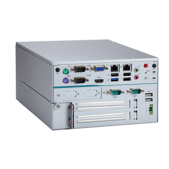
eBOX638-842-FL Series User’s Manual I/O Outlets The following figures show you I/O outlets on front view of the eBOX638-842-FL. Front View 1 x PS/2 KB/MS LEDs 1 x RS-232/422/485 (COM1) 1 x RS-232 (COM4) 1 x VGA 1 x RS-232 (COM3) 1 x HDMI 2 x USB 2.0 1 x LAN1... -
Page 15: Packing List
2-pin terminal block connector x 1 1 x PCI riser card or 1 x PCIe x1 riser Note: If you cannot find this package or any items are missing, please contact Axiomtek distributors immediately. Model List ® ®... - Page 16 eBOX638-842-FL Series User’s Manual This page is intentionally left blank. Introduction...
-
Page 17: Section 2 Hardware Installation
eBOX638-842-FL Series User’s Manual SECTION 2 HARDWARE INSTALLATION The eBOX638-842-FL is convenient for your various hardware configurations, such as Memory Module, HDD (Hard Disk Drive), SSD (Solid State Drive), PCI Express mini Card and PCI/PCIe x1 slot. Section 2 contains guidelines for hardware installation. Installation of the Memory Module Step 1 Turn off the system, and unplug the power cord. -
Page 18: Installation Of The Express Mini Card
eBOX638-842-FL Series User’s Manual Installation of the Express Mini Card Step 1 Turn off the system, and unplug the power cord. Step 2 Eight screws on the top heatsink are used to fasten the heatsink to the chassis. Step 3 Remove the top cover and locate Express Mini card slot within the red line marked. -
Page 19: Installation Of The 2.5" Sata Device
eBOX638-842-FL Series User’s Manual Installation of the 2.5" SATA Device Step 1 Turn off the system, and unplug the power cord. Step 2 Eight screws on the top heatsink are used to fasten the heatsink to the chassis. Step 3 Locate SSD/HDD within the red block marked at the back side. Step 4 Connect SATA cable with the SSD/HDD and then fasten four screws at the back side of chassis. -
Page 20: Installation Of The Pci/Pcie Card
eBOX638-842-FL Series User’s Manual Installation of the PCI/PCIe Card Step 1 Turn off the system. Step 2 Unplug the power-cord. Step 3 Turning counterclockwise to loosen the thumb screw as marked and then pull the lower left cover out. Step 4 Identify the location of the PCI/PCIe slot as below red marked. -
Page 21: Installation Of The Flexible Io Modules
eBOX638-842-FL Series User’s Manual Installation of the Flexible IO modules The eBOX638-842 provides an optional window for customer add flexible I/O modules, according to different modules , please follow the below Instructions: -AX92902 LAN Module (RJ45 connector*1) -AX92904 DIO Module (DB44 connector*1) -AX92903 CAN Bus/CAN Open Module (DB9 connector*1) -AX92906 COM Module (DB9 connector*2) Flexible IO window... - Page 22 eBOX638-842-FL Series User’s Manual Step 4 Loosen the two screws of flexible IO door and push the hole which is not punched through. Step 5 Insert the CAN Bus mini PCIe card (One mini card with one DB 9 connector) Step 6 Assemble CAN Bus connector with bracket and fasten the CAN Bus connector with bracket onto the chassis, and then connect the CAN Bus cable to the mini PCIe card.
-
Page 23: Section 3 Jumper & Connector Settings
eBOX638-842-FL Series User’s Manual SECTION 3 JUMPER & CONNECTOR SETTINGS Proper jumper settings configure the eBOX638-842-FL to meet various application needs. Hereby all jumpers settings along with their default settings are listed for devices onboard. Board Layout Jumper & Connector Settings... - Page 24 eBOX638-842-FL Series User’s Manual Jumper & Connector Settings...
- Page 25 LVDS Backlight PW M/CCFL Select Audio Connector (CN30) Jumper (JP3) COM1 Connector (CN18) Note: It is strongly recommended that any unmentioned jumper settings should not be modified without instructions by Axiomtek FAEs. Any modifications without instructions might cause system failure. Jumper & Connector Settings...
-
Page 26: Summary Of Jumper Settings
eBOX638-842-FL Series User’s Manual Summary of Jumper settings Proper jumper settings configure the eBOX638-842-FL to meet various application purposes. A table of all jumpers and their default settings is listed below. Jumpers Descriptions Settings Clear CMOS 1-2 Close AT/ATX Power Mode Select 1-2 Close Default: ATX Mode 1-2 Close... -
Page 27: Clear Cmos (Clr_Cmos)
eBOX638-842-FL Series User’s Manual 3.2.1 Clear CMOS (CLR_CMOS) This jumper allows you to clear the Real Time Clock (RTC) RAM in CMOS. You can clear the CMOS memory of date, time, and system setup parameters by erasing the CMOS RTC RAM data. -
Page 28: Com 1 Rs-232/422/485 Mode Select (Jp5, Jp6, Jp7)
eBOX638-842-FL Series User’s Manual 3.2.3 COM 1 RS-232/422/485 Mode Select (JP5, JP6, JP7) Use these jumpers (3x2-pin p=2.54mm) to set COM 1 port to operate as RS-232, RS-422 or RS-485 communication mode. Functions Settings JP5 1-2 close RS-232 mode JP6 3-5, 4-6 close (Default) JP7 3-5, 4-6 close JP5 3-4 close... -
Page 29: Connectors
eBOX638-842-FL Series User’s Manual Connectors Connectors connect the board with other parts of the system. Loose or improper connection might cause problems. Make sure all connectors are properly and firmly connected. Here is a summary table shows you all connectors and button on the eBOX638-842-FL Series. External connectors Sections DC-in Phoenix Power Connector... -
Page 30: 3.3.1 Dc-In Phoenix Power Connector
eBOX638-842-FL Series User’s Manual 3.3.1 DC-in Phoenix Power Connector The system supports a wide range Phoenix DC-in connector for system power input. Pins Signals 3.3.2 ATX Power On/OFF Button The ATX power button is on the I/O side. It can allow users to control eBOX638-842-FL power on/off. -
Page 31: Vga Connector (Cn8)
eBOX638-842-FL Series User’s Manual 3.3.4 VGA Connector (CN8) The CN8 is a high rise 15-pin D-Sub connector which is commonly used for VGA monitor. This VGA interface configuration can be configured via software utility. Pins Signals Pins Signals Green Blue N.C. -
Page 32: Lan And Usb Connectors (Cn24 And Cn25)
eBOX638-842-FL Series User’s Manual 3.3.6 LAN and USB Connectors (CN24 and CN25) The board comes with two high performance plug and play Ethernet interfaces (RJ-45) which are fully compliant with the IEEE 802.3 standard. Connection can be established by plugging one end of the Ethernet cable into this RJ-45 connector and the other end to a 1000/100/10- Base-T hub. - Page 33 eBOX638-842-FL Series User’s Manual The CN25 has lower double-deck connector for USB 3.0 port 1 and USB 2.0 port 3. Pins LAN1 Signals Pins LAN1 Signals MDI0+ MDI2+ MDI0- MDI2- MDI1+ MDI3+ MDI1- MDI3- 100 LAN LED (Green)/1000 LAN LED (Orange) Active LED (Yellow) Pins USB 3.0 Signals...
-
Page 34: Hdmi Connector (Cn29)
eBOX638-842-FL Series User’s Manual 3.3.7 HDMI Connector (CN29) The HDMI (High-Definition Multimedia Interface) interface is available through this connector. Pins Signals Pins Signals HDMI OUT_DATA2+ HDMI HDMI OUT_DATA2- OUT_DATA1+ HDMI OUT_DATA1- HDMI OUT_DATA0+ HDMI HDMI OUT_Clock+ OUT_DATA0- HDMI OUT_Clock- N.C. N.C. -
Page 35: Usb 3.0 Internal Connector
eBOX638-842-FL Series User’s Manual 3.3.9 USB 3.0 Internal Connector This internal connector provides USB Rev. 3.0 supporting transmission rate up to 5Gbps and fuse protect. Pins Signals -DATA1 +DATA1 -SRX1 +SRX1 -STX1 +STX1 3.3.10 Audio Jack (CN30) The board provides HD audio jack on the rear I/O. Install audio driver, and then attach audio devices to CN30. -
Page 36: Full-Size Pci-Express Mini Card Connector (Cn27)
eBOX638-842-FL Series User’s Manual 3.3.12 Full-size PCI-Express Mini Card Connector (CN27) This is a PCI-Express Mini Card connector applying to PCI-Express or USB 2.0. It complies with PCI-Express Mini Card Spec. V1.2. 3.3.13 mSATA Slot (CN28) Jumper & Connector Settings... -
Page 37: Section 4 Bios Setup Utility
eBOX638-842-FL Series User’s Manual SECTION 4 BIOS SETUP UTILITY This section provides users with detailed descriptions in terms of how to set up basic system configurations through the BIOS setup utility. Starting To enter the setup screens, follow the steps below: Turn on the computer and press the <Del>... -
Page 38: Main Menu
eBOX638-842-FL Series User’s Manual Main Menu The first time you enter the setup utility, you will enter the Main setup screen. You can always return to the Main setup screen by selecting the Main tab. System Time/Date can be set up as described below. -
Page 39: Advanced Menu
eBOX638-842-FL Series User’s Manual Advanced Menu Launch PXE OpROM Use this item to enable or disable the boot ROM function of the onboard LAN chip when the system boots up. The Advanced menu also allows users to set configuration of the CPU and other system devices. - Page 40 eBOX638-842-FL Series User’s Manual Super IO Configuration You can use this screen to select options for the Super IO Configuration, and change the value of the selected option. A description of the selected item appears on the right side of the screen.
- Page 41 eBOX638-842-FL Series User’s Manual COM1 Serial Port Enable or disable serial port 1. The optimal setting for base I/O address is 3F8h and for interrupt request address is IRQ4. Change Settings Select an optimal setting for serial port. BIOS Setup Utility...
- Page 42 eBOX638-842-FL Series User’s Manual H/W Monitor This screen monitors hardware health status. This screen displays the temperature of system and CPU, stem voltages (VCC_CPU, VCC_DDR, +12V, +5V, +3.3V). BIOS Setup Utility...
- Page 43 eBOX638-842-FL Series User’s Manual ACPI Settings You can use this screen to select options for the ACPI configuration, and change the value of the selected option. A description of the selected item appears on the right side of the screen. ACPI Sleep State Select the highest ACPI sleep state the system will enter when the suspend button is pressed.
- Page 44 eBOX638-842-FL Series User’s Manual Display Configuration Primary IGFX Boot Display Select the video device which will be activated during POST (Power-On Self Test). The default is Auto. BIOS Setup Utility...
- Page 45 eBOX638-842-FL Series User’s Manual CPU Configuration This screen shows the CPU Configuration, and you can change the value of the selected option. Socket 0 CPU Information This item is for CPU inform ation. Intel Virtualization Technology Enable or disable Intel Virtualization Technology. When enabled, a VMM (Virtual Machine Mode) can utilize the additional hardware capabilities.
- Page 46 eBOX638-842-FL Series User’s Manual IDE Configuration In the IDE Configuration menu, you can see the currently installed hardware in the SATA ports. During system boot up, the BIOS automatically detects the presence of SATA devices. Serial-ATA (SATA) Enable or disable the SATA controller feature. SATA Speed Support Select SATA speed support.
- Page 47 eBOX638-842-FL Series User’s Manual OS Configuration You can use this screen to select options for the USB Configuration, and change the value of the selected option. A description of the selected item appears on the right side of the screen. OS Selection This item allows user to select the proper Operating System.
- Page 48 eBOX638-842-FL Series User’s Manual CSM Configuration Enable or disable TXE firmware. CSM Support Enable or disable CSM (Compatibility Support Module) support. PXE BootRom Enable or disable the Preboot eXecution Environment (PXE) boot ROM function of the onboard LAN chip during system boots up. BIOS Setup Utility...
- Page 49 eBOX638-842-FL Series User’s Manual USB Configuration USB Devices Display all detected USB devices. Legacy USB Support Use this item to enable or disable legacy support for USB devices. The default setting is Enabled. Auto option disables legacy support if no USB devices are connected. Disable option will keep USB devices available only for EFI applications.
- Page 50 eBOX638-842-FL Series User’s Manual Utility Configuration BIOS Flash Utility BIOS flash utility configuration. For more detailed information, please refer to Appendix A BIOS Setup Utility...
-
Page 51: Chipset Menu
eBOX638-842-FL Series User’s Manual Chipset Menu The Chipset menu allows users to change the advanced chipset settings. You can select any of the items in the left frame of the screen to go to the sub menus: ► North Bridge ►... - Page 52 eBOX638-842-FL Series User’s Manual North Bridge This screen is for North Bridge configuration. BIOS Setup Utility...
- Page 53 eBOX638-842-FL Series User’s Manual South Bridge Audio Controller Control detection of the audio device. - Disabled: Audio device will be unconditionally disabled. - Enabled: Audio device will be unconditionally enabled. BIOS Setup Utility...
-
Page 54: Security Menu
eBOX638-842-FL Series User’s Manual Security Menu The Security menu allows users to change the security settings for the system. Administrator Password This item indicates whether an administrator password has been set (installed or uninstalled). User Password This item indicates whether an user password has been set (installed or uninstalled). BIOS Setup Utility... -
Page 55: Boot Menu
eBOX638-842-FL Series User’s Manual Boot Menu The Boot menu allows users to change boot options of the system. Setup Prompt Timeout Number of seconds to wait for setup activation key. 65535(0xFFFF) means indefinite waiting. Bootup NumLock State Use this item to select the power-on state for the keyboard NumLock. FullScreen Logo Enable or disable OEM logo display at system startup. -
Page 56: Save & Exit Menu
eBOX638-842-FL Series User’s Manual Save & Exit Menu The Save & Exit menu allows users to load your system configuration with optimal or fail-safe default values. Save Changes and Reset When completed the system configuration changes, select this option to leave Setup and reboot the computer so the new system configurations take effect. - Page 57 eBOX638-842-FL Series User’s Manual Restore User Defaults It automatically sets all Setup options to a complete set of User Defaults when users select this option. Select Restore User Defaults from the Save & Exit menu and press <Enter>. Boot Override Select a drive to immediately boot that device regardless of the current boot order.
- Page 58 eBOX638-842-FL Series User’s Manual This page is intentionally left blank. BIOS Setup Utility...
-
Page 59: Appendix Abios Flash Utility
Please read and follow the instructions below carefully. In your USB flash drive, create a new folder and name it “Axiomtek”, see figure below. Copy BIOS ROM file (e.g. MANO842.V200) to “Axiomtek” folder. - Page 60 USB drive is attached to the system. That’s why, you can see only one device is displayed in figure below. Select the USB drive containing BIOS ROM file you want to update using the <> or <> key. Then press <Enter> to get into “Axiomtek” folder. BIOS Flash Utility...
- Page 61 eBOX638-842-FL Series User’s Manual Now you can see the BIOS ROM file on the screen, press <Enter> to select. MANO842V.200 Select Start to flash system BIOS option to begin updating procedure. Please wait while BIOS completes the entire flash update process: erase data, write new data and verify data.
- Page 62 eBOX638-842-FL Series User’s Manual 10. When you see the following figure, press <Enter> to finish the update process. After that the system will shut down and restart immediately. BIOS Flash Utility...
Need help?
Do you have a question about the eBOX638-842-FL-2 PCI and is the answer not in the manual?
Questions and answers