
Related Manuals for AXIOMTEK MANO871 Series


Summary of Contents for AXIOMTEK MANO871 Series
- Page 1 MANO871 Series ® Intel Socket 1155 Core i7 / Core ® i5 / Core i3 / Celeron Processor All-In-One Mini ITX Board with HDMI / DVI-I / LVDS User’s Manual...
- Page 2 Axiomtek does not make any commitment to update the information in this manual. Axiomtek reserves the right to change or revise this document and/or product at any time without notice. No part of this document may be reproduced, stored in a retrieval system, or transmitted, in any form or by any means, electronic, mechanical, photocopying, recording, or otherwise, without the prior written permission of Axiomtek Co., Ltd.
-
Page 3: Esd Precautions
Wear a wrist-grounding strap, available from most electronic component stores, when handling boards and components. Trademarks Acknowledgments Axiomtek is a trademark of Axiomtek Co., Ltd. ® Windows is a trademark of Microsoft Corporation. AMI is a trademark of American Megatrend Inc. -
Page 4: Table Of Contents
Table of Contents Disclaimers ..................... ii ESD Precautions ................... iii Chapter 1 Introduction ..........1 Features ....................1 Specifications ..................2 Utilities Supported ................3 Chapter 2 Board and Pin Assignments ....5 Board Dimensions and Fixing Holes ..........5 Board Layout .................. - Page 5 Chapter 3 Hardware Installation ......27 Installing the Processor ..............27 Installing the Memory ............... 33 Chapter 4 Hardware Description ......35 Microprocessors ................35 BIOS ....................35 System Memory ................. 35 I/O Port Address Map ................ 36 Interrupt Controller (IRQ) Map ............38 Memory Map ..................
- Page 6 This page is intentionally left blank.
-
Page 7: Chapter 1 Introduction
MANO871 Series All-In-One Mini ITX Board Chapter 1 Introduction ® ® The MANO871 is a Mini ITX board with LGA1155 socket for Intel Core i7 / Intel Core i5 / ® ® ® Intel Core i3 / Intel Celeron (G6950) desktop processor with 22nm technology. The board ®... -
Page 8: Specifications
MANO871 Series All-In-One Mini ITX Board Specifications ® Intel Core i7 desktop processor. ® Intel Core i5 desktop processor. ® Intel Core i3 desktop processor. ® ® Intel Celeron desktop processors. System Chipset ®... -
Page 9: Utilities Supported
MANO871 Series All-In-One Mini ITX Board Watchdog Timer 1~255 seconds; up to 256 levels. Expansion Interface One PCI-Express x16 slot. Ethernet ® LAN1 – Intel 82579LM supports 10/100/1000Mbps. ® LAN2 – Intel 82583V supports 10/100/1000Mbps. - Page 10 MANO871 Series All-In-One Mini ITX Board This page is intentionally left blank. Introduction...
-
Page 11: Board And Pin Assignments
MANO871 Series All-In-One Mini ITX Board Chapter 2 Board and Pin Assignments Board Dimensions and Fixing Holes Top Side Board and Pin Assignments... - Page 12 MANO871 Series All-In-One Mini ITX Board Bottom Side Board and Pin Assignments...
-
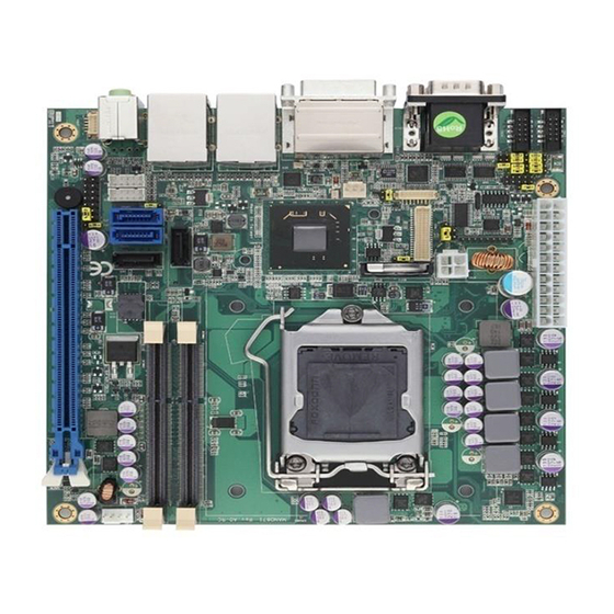
Page 13: Board Layout
MANO871 Series All-In-One Mini ITX Board Board Layout Top Side I/O Bracket Board and Pin Assignments... - Page 14 MANO871 Series All-In-One Mini ITX Board Bottom Side Board and Pin Assignments...
-
Page 15: Jumper And Switch Settings
And remove jumper clip from 2 jumper pins to open. The following illustration shows how to set up jumper. Before applying power to MANO871 Series, please make sure all of the jumpers and switch are in factory default position. Below you can find a summary table and onboard default settings. -
Page 16: Restore Bios Optimal Defaults (Jp1)
MANO871 Series All-In-One Mini ITX Board 2.3.1 Restore BIOS Optimal Defaults (JP1) Put jumper clip to pin 2-3 for a few seconds then move it back to pin 1-2. Doing this procedure can restore BIOS optimal defaults. Function Setting Normal operation (Default) -
Page 17: Auto Power On (Jp8)
MANO871 Series All-In-One Mini ITX Board 2.3.6 Auto Power On (JP8) If JP8 is enabled for AC power input, the system will be automatically power on without pressing soft power button. If JP8 is disabled for AC power input, it is necessary to manually press soft power button to power on the system. -
Page 18: Pci-Express Bifurcation Setting (Sw1)
MANO871 Series All-In-One Mini ITX Board 2.3.10 PCI-Express Bifurcation Setting (SW1) SW1 is for PCI-Express bifurcation setting. See table below for detailed information. Function Setting SW1-1 OFF SW1-2 OFF One x16 PCI-Express (Default) SW1-1 OFF SW1-2 ON Two x8 PCI-Express... -
Page 19: Connectors
MANO871 Series All-In-One Mini ITX Board Connectors Signals go to other parts of the system through connectors. Loose or improper connection might cause problems, please make sure all connectors are properly and firmly connected. Here is a summary table which shows all connectors on the hardware. -
Page 20: Atx Power Connectors (Cn2 And Atx1)
MANO871 Series All-In-One Mini ITX Board 2.4.1 ATX Power Connectors (CN2 and ATX1) Steady and sufficient power can be supplied to all components on the board by connecting power connector. Please make sure all components and devices are properly installed before connecting the power connector. -
Page 21: Serial Ata Connectors (Cn3, Cn4, Sata1 And Sata2)
MANO871 Series All-In-One Mini ITX Board 2.4.2 Serial ATA Connectors (CN3, CN4, SATA1 and SATA2) These Serial Advanced Technology Attachment (Serial ATA or SATA) connectors are for high-speed SATA interfaces. They are computer bus interfaces for connecting to devices such as hard disk drives. -
Page 22: Lvds Connector (Cn6)
MANO871 Series All-In-One Mini ITX Board 2.4.3 LVDS Connector (CN6) This board has a 40-pin connector (CN6) for LVDS LCD interface. It is strongly recommended to use the matching JST SHDR-40VS-B 40-pin connector for LVDS interface. Pin 1~6 VCCM can be set to +3.3V, +5V or +12V level by JP2 and JP3 (see section 2.3.2). - Page 23 MANO871 Series All-In-One Mini ITX Board 24-bit single channel 18-bit dual channel Pin Signal Pin Signal Pin Signal Pin Signal 1 VCCM VCCM VCCM VCCM VCCM VCCM VCCM VCCM VCCM VCCM VCCM VCCM EDID DATA EDID CLK EDID DATA EDID CLK...
-
Page 24: Inverter Connectors (Cn7)
MANO871 Series All-In-One Mini ITX Board 2.4.4 Inverter Connectors (CN7) The CN7 is DF13-8P-1.25V 8-pin connector for inverter. We strongly recommend you to use the matching DF13-8S-1.25C connector to avoid malfunction. Signal VBL1 (+12V level) VBL1 (+12V level) VBL2 (+5V level) -
Page 25: Lan And Usb Connectors (Cn10 And Cn11)
MANO871 Series All-In-One Mini ITX Board 2.4.6 LAN and USB Connectors (CN10 and CN11) The board comes with two high performance plug and play ethernet interfaces (RJ-45) which are fully compliant with the IEEE 802.3 standard. Connection can be established by plugging one end of the ethernet cable into this RJ-45 connector and the other end to a 1000/100/10-Base-T hub. -
Page 26: Dvi-I Connector (Cn12)
MANO871 Series All-In-One Mini ITX Board CN11 LAN2 Signal LAN2 Signal (WG82583V) (WG82583V) MDI0+ MDI2+ MDI0- MDI2- MDI1+ MDI3+ MDI1- MDI3- 100 LAN LED (Green)/ 1000 LAN LED (Orange) Active LED USB Signal USB Signal USB_VCC (+5V level USB_VCC (+5V level... -
Page 27: Com Connectors (Cn13, Cn14 And Cn15)
MANO871 Series All-In-One Mini ITX Board 2.4.8 COM Connectors (CN13, CN14 and CN15) The COM3 and COM4 interfaces are available through CN13 and CN14, respectively. Each of these connectors is a 2x5 pin 2.0 pitch box header, see table below for its pin assignments. -
Page 28: Internal Audio Connector (Cn17)
MANO871 Series All-In-One Mini ITX Board 2.4.10 Internal Audio Connector (CN17) CN17 is an internal audio connector for line-out and microphone. Signal Lineout-L Lineout-R MIC-in 2.4.11 HDMI Connector (CN18) The HDMI (High-Definition Multimedia Interface) is a compact digital interface which is capable of transmitting high-definition video and high-resolution audio over a single cable. -
Page 29: Pci-Express Mini Card And Msata Connector (Scn2)
MANO871 Series All-In-One Mini ITX Board 2.4.12 PCI-Express Mini Card and mSATA Connector (SCN2) SCN2 (soldered on the bottom side) is a PCI-Express Mini Card connector which supports a PCI-Express x1 link, a SATA link and a USB 2.0 link. A PCI-Express Mini Card can be applied to either PCI-Express or USB 2.0 and SATA also. -
Page 30: Fan Connectors (Fan1 And Fan2)
MANO871 Series All-In-One Mini ITX Board 2.4.13 FAN Connectors (FAN1 and FAN2) Fans are always needed for cooling down CPU and system temperature. The board has two fan connectors. You can find fan speed option(s) at BIOS Setup Utility if either fan is installed. -
Page 31: Digital I/O Connector (Jp9)
MANO871 Series All-In-One Mini ITX Board Power On/Off Button Pin 9 and 10 connect the power button on front panel to the CPU board, which allows users to turn on or off power supply. System Reset Switch Pin 11 and 12 connect the case-mounted reset switch that reboots your computer without turning off the power switch. - Page 32 MANO871 Series All-In-One Mini ITX Board This page is intentionally left blank. Board and Pin Assignments...
-
Page 33: Chapter 3 Hardware Installation
MANO871 Series All-In-One Mini ITX Board Chapter 3 Hardware Installation ® Before installing the processor, please access Intel website for more detail information of Processor Integration Video (LGA1155): http://www.intel.com/support/tw/processors/sb/CS-030860.htm Installing the Processor The LGA1155 processor socket comes with a cover to protect the processor. Please install the... - Page 34 MANO871 Series All-In-One Mini ITX Board Note: Vertical removal is NOT recommended, as it requires higher force and can lead to socket contact damage. Caution: Never touch fragile socket contacts to avoid damage and do not touch processor sensitive contacts at any time during installation.
- Page 35 MANO871 Series All-In-One Mini ITX Board Grasp the processor with thumb and index finger along the top and bottom edges. (Do not touch the orientation notches.) The socket will have cutouts for your fingers to fit into (see image below).
- Page 36 MANO871 Series All-In-One Mini ITX Board Verify that package is within the socket body and properly connected to orientation keys. Close the socket (see image below): 1. Gently lower the load plate. 2. Make sure load plate's front edge slides under the shoulder screw cap as the lever is lowered.
- Page 37 MANO871 Series All-In-One Mini ITX Board Screw the CPU cooling fan onto the board. Make sure the CPU fan is plugged to the CPU fan connector. Step5 Removing the processor: Open the socket: Disengage the load lever. Open the load plate ...
- Page 38 MANO871 Series All-In-One Mini ITX Board Hold protective cover at 45 degree angle to the LGA1155 Socket. Carefully lower protective cover on hinge side first, to contact with the outside wall of the LGA1155 Socket: Engage protective cover retention features to outside of LGA1155 Socket, AND align 2 cover corners to socket corners (This step is critical to avoid Bent Contact Damage!).
-
Page 39: Installing The Memory
MANO871 Series All-In-One Mini ITX Board Installing the Memory The board supports two 204-pin DDR3 SO-DIMM memory sockets with maximum memory capacity up to 16GB. Note: A DDR3 module has the same physical dimensions as a DDR2 SO-DIMM but is notched differently to prevent installation on a DDR2 SO-DIMM socket. - Page 40 MANO871 Series All-In-One Mini ITX Board This page is intentionally left blank. Hardware Installation...
-
Page 41: Chapter 4 Hardware Description
CPU from damages. BIOS The MANO871 Series uses AMI Plug and Play BIOS with a single 64Mbit SPI Flash. System Memory The MANO871 Series supports two 204-pin DDR3 SO-DIMM sockets for a maximum memory of 16GB DDR3 SDRAMs. -
Page 42: I/O Port Address Map
MANO871 Series All-In-One Mini ITX Board I/O Port Address Map ® ® The Intel Core i7 / Core i5 / Core i3 / Celeron processors communicate via I/O ports. Total 1KB port addresses are available for assigning to other devices via I/O expansion cards. - Page 43 MANO871 Series All-In-One Mini ITX Board Hardware Description...
-
Page 44: Interrupt Controller (Irq) Map
MANO871 Series All-In-One Mini ITX Board Interrupt Controller (IRQ) Map The interrupt controller (IRQ) mapping list is shown as follows: Hardware Description... -
Page 45: Memory Map
MANO871 Series All-In-One Mini ITX Board Memory Map The memory mapping list is shown as follows: Hardware Description... - Page 46 MANO871 Series All-In-One Mini ITX Board This page is intentionally left blank. Hardware Description...
-
Page 47: Ami Bios Setup Utility
MANO871 Series All-In-One Mini ITX Board Chapter 5 AMI BIOS Setup Utility The AMI UEFI BIOS provides users with a built-in setup program to modify basic system configuration. All configured parameters are stored in a flash chip to save the setup information whenever the power is turned off. -
Page 48: Main Menu
MANO871 Series All-In-One Mini ITX Board Hot Keys Description Left/Right The Left and Right <Arrow> keys allow you to select a setup screen. The Up and Down <Arrow> keys allow you to select a setup screen or Up/Down sub-screen. -
Page 49: Advanced Menu
MANO871 Series All-In-One Mini ITX Board System Date/Time Use this option to change the system time and date. Highlight System Time or System Date using the <Arrow> keys. Enter new values through the keyboard. Press the <Tab> key or the <Arrow>... - Page 50 MANO871 Series All-In-One Mini ITX Board ACPI Settings You can use this screen to select options for the ACPI configuration, and change the value of the selected option. A description of the selected item appears on the right side of the screen.
- Page 51 MANO871 Series All-In-One Mini ITX Board Trusted Computing This screen provides function for specifying the TPM settings. Security Device Support Use this item to enable or disable BIOS support for security device. Current Status Information Display current TPM status information.
- Page 52 MANO871 Series All-In-One Mini ITX Board CPU Configuration This screen shows the CPU information. EIST ® Enable or disable Intel SpeedStep. When enabled, CPU speed is controlled by the operating system. When disabled, CPU runs at its default speed.
- Page 53 MANO871 Series All-In-One Mini ITX Board SATA Configuration In this Configuration menu, you can see the currently installed hardware in the SATA ports. During system boot up, the BIOS automatically detects the presence of SATA devices. SATA Controller(s) Enable or disable SATA device.
- Page 54 MANO871 Series All-In-One Mini ITX Board PCH-FW Configuration This screen displays Management Engine (ME) Firmware information. AMT Configuration Use this screen to configure AMT parameters. Intel AMT ® Enable or disable Intel Active Management Technology BIOS Extension. Disable ME Enable or disable ME functionality.
- Page 55 MANO871 Series All-In-One Mini ITX Board USB Configuration You can use this screen to select options for the USB Configuration, and change the value of the selected option. A description of the selected item appears on the right side of the screen.
- Page 56 MANO871 Series All-In-One Mini ITX Board NCT6627UD Super IO Configuration You can use this screen to select options for the Super IO Configuration, and change the value of the selected option. A description of the selected item appears on the right side of the screen.
- Page 57 MANO871 Series All-In-One Mini ITX Board NCT6627UD HW Monitor Use this screen for Smart Fan configuration and hardware health status monitoring. This screen displays the temperature of system and CPU, cooling fan speed in RPM and system voltages (VCORE, +12V, +3.3V and +5V).
-
Page 58: Chipset Menu
MANO871 Series All-In-One Mini ITX Board Chipset Menu The Chipset menu allows users to change the advanced chipset settings. You can select any of the items in the left frame of the screen to go to the sub menus: ►... - Page 59 MANO871 Series All-In-One Mini ITX Board PCH-IO Configuration This screen allows you to set PCH parameters. USB Configuration Use this item for USB configuration settings. PCH Azalia Configuration Use this item for PCH Azalia configuration settings. Launch PXE OpROM policy Control the execution of UEFI and Legacy PXE OpROM.
- Page 60 MANO871 Series All-In-One Mini ITX Board System Agent (SA) Configuration This screen shows System Agent information and provides function for specifying related parameters. For items marked with “”, please press <Enter> for more options. VT-d ® Enable or disable Intel chipset virtualization technology for directed I/O.
- Page 61 MANO871 Series All-In-One Mini ITX Board Graphics Configuration Primary Display Allow you to select which graphics controller to use as the primary boot device. Primary IGFX Boot Display Allow you to select the display device which will be activated during POST. This has no effect if external graphics present.
-
Page 62: Boot Menu
MANO871 Series All-In-One Mini ITX Board Boot Menu The Boot menu allows users to change boot options of the system. Setup Prompt Timeout Number of seconds to wait for setup activation key. 65535(0xFFFF) means indefinite waiting. Bootup NumLock State Use this item to select the power-on state for the keyboard NumLock. -
Page 63: Security Menu
MANO871 Series All-In-One Mini ITX Board Security Menu The Security menu allows users to change the security settings for the system. Administrator Password This item indicates whether an administrator password has been set (installed or uninstalled). User Password This item indicates whether an user password has been set (installed or uninstalled). -
Page 64: Save & Exit Menu
MANO871 Series All-In-One Mini ITX Board Save & Exit Menu The Save & Exit menu allows users to load your system configuration with optimal or fail-safe default values. Save Changes and Exit When you have completed the system configuration changes, select this option to leave Setup and return to Main Menu. - Page 65 MANO871 Series All-In-One Mini ITX Board Discard Changes Select this option to quit Setup without making any permanent changes to the system configuration. Select Discard Changes from the Save & Exit menu and press <Enter>. Select Yes to discard changes.
- Page 66 MANO871 Series All-In-One Mini ITX Board This page is intentionally left blank. AMI BIOS Setup Utility...
-
Page 67: Appendix A Watchdog Timer
MANO871 Series All-In-One Mini ITX Board Appendix A Watchdog Timer About Watchdog Timer After the system stops working for a while, it can be auto-reset by the watchdog timer. The integrated watchdog timer can be set up in the system reset mode by program. - Page 68 MANO871 Series All-In-One Mini ITX Board Program Example 2E, 87 2E, 87 2E, 07 2F, 08 Logical Device 8 2E, 30 Activate 2F, 01 2E, F5 2F, N Set Minute or Second; N=08 (Min), 00(Sec) 2E, F6 2F, M Set Value;...
-
Page 69: Appendix B Digital I/O
MANO871 Series All-In-One Mini ITX Board Appendix B Digital I/O Using Digital Output Function O 2E 87 O 2E 87 O 2E 07 O 2F 08 O 2E 30 O 2F 02 Setting DIO is active O 2E E0 O 2F 00 00: The respective DIO is programmed as an output port... - Page 70 MANO871 Series All-In-One Mini ITX Board This page is intentionally left blank. Digital I/O...
-
Page 71: Appendix C Configuring Sata For Raid
MANO871 Series All-In-One Mini ITX Board Appendix C Configuring SATA for RAID Configuring SATA Hard Drive(s) for RAID Function Before you begin the SATA configuration, please prepare: Two SATA hard drives (to ensure optimal performance, it is recommended that you use two hard drives with identical model and capacity). - Page 72 MANO871 Series All-In-One Mini ITX Board Turn on your system, and then press the <Del> button to enter BIOS Setup during running 2.1. POST (Power-On Self Test). If you want to create RAID, just go to the Advanced Settings menu, select the “SATA Mode Selection”, and press <Enter> for more options. A list of options appears, please select “RAID”.
- Page 73 MANO871 Series All-In-One Mini ITX Board 3. Configuring RAID by the RAID BIOS. Enter the RAID BIOS setup utility to configure a RAID array. Skip this step and proceed if you do not want to create a RAID. After the POST memory testing and before the operating system booting, a message 3.1.
- Page 74 MANO871 Series All-In-One Mini ITX Board After entering the Create Volume Menu screen, you can type the disk array name with 3.3. 1~16 letters (letters cannot be special characters) in the item “Name”. When finished, press <Enter> to select a RAID level. There are three RAID levels: RAID0, 3.4.
- Page 75 MANO871 Series All-In-One Mini ITX Board Set the stripe block size. The KB is the standard unit of stripe block size. The stripe block 3.5. size can be 4KB to 128KB. After the setting, press <Enter> for the array capacity.
- Page 76 MANO871 Series All-In-One Mini ITX Board When prompting the confirmation, press <Y> to create this volume, or <N> to cancel the 3.7. creation. After the creation is completed, you can see detailed information about the RAID Array in the Disk/Volume Information section, including RAID mode, disk block size, disk name, and disk capacity, etc.
- Page 77 MANO871 Series All-In-One Mini ITX Board Delete RAID volume If you want to delete a RAID volume, select the Delete RAID Volume option in Main Menu. Press <Enter> and follow on-screen instructions. Please press <Esc> to exit the RAID BIOS utility. Now, you can proceed to install a SATA driver controller and the operating system.
- Page 78 MANO871 Series All-In-One Mini ITX Board Restart your system to boot the Windows 2000/XP Setup disk, and press <F6> button as 5.1. soon as you see the message "Press F6 if you need to install a 3rd party SCSI or RAID driver".
- Page 79 MANO871 Series All-In-One Mini ITX Board If the Setup correctly recognizes the driver of the floppy disk, a controller menu will appear 5.3. below. Use the <Arrow> keys to select “Intel(R) Desktop/Workstation/Server Express Chipset SATA RAID Controller” and press <Enter>. Then it will begin to load the SATA driver from the floppy disk.
- Page 80 MANO871 Series All-In-One Mini ITX Board This page is intentionally left blank. Configuring SATA for RAID...
-
Page 81: Appendix D Intel Iamt Settings
MANO871 Series All-In-One Mini ITX Board Appendix D ® Intel iAMT Settings ® ® The Intel Active Management Technology (Intel iAMT) has decreased a major barrier to IT efficiency that uses built-in platform capabilities and popular third-party management and security applications to allow IT a better discovering, healing, and protection their networked computing assets. -
Page 82: Set And Change Password
MANO871 Series All-In-One Mini ITX Board Set and Change Password You will be asked to set a password when first log in. The default password is “admin”. ® Intel iAMT Settings... - Page 83 MANO871 Series All-In-One Mini ITX Board You will be asked to change the password before setting ME. You must confirm your new password while revising. The new password must contain: (example: !!11qqQQ) (default value). Eight characters One upper case ...
-
Page 84: Intel ® Iamt Web Console
MANO871 Series All-In-One Mini ITX Board ® Intel iAMT Web Console ® From a web browser, please type http://(IP ADDRESS):16992, which connects to Intel iAMT Web. Example: http://10.1.40.214:16992 To log on, you will be required to type in username and password for access to the Web. - Page 85 MANO871 Series All-In-One Mini ITX Board Enter the iAMT Web. Click Remote Control, and select commands on the right side. When you have finished using the iAMT Web console, close the Web browser. ® Intel iAMT Settings...
Need help?
Do you have a question about the MANO871 Series and is the answer not in the manual?
Questions and answers