Table of Contents
Advertisement
Quick Links
Advertisement
Table of Contents

Subscribe to Our Youtube Channel
Related Manuals for AXIOMTEK eBOX621-801-FL Series


Summary of Contents for AXIOMTEK eBOX621-801-FL Series
- Page 1 Series Embedded System User’s Manual...
- Page 2 Axiomtek does not make any commitment to update the information in this manual. Axiomtek reserves the right to change or revise this document and/or product at any time without notice No part of this document may be reproduced, stored in a retrieval system, or transmitted, in any form or by any means, electronic, mechanical, photocopying, recording, or otherwise, without the prior written permission of Axiomtek Co., Ltd.
-
Page 3: Safety Precautions
Safety Precautions Before getting started, please read the following important safety precautions. The eBOX621-801-FL does not come equipped with an operating system. An operating system must be loaded first before installing any software into the computer. Be sure to ground yourself to prevent static charge when installing the internal components. Use a grounding wrist strap and place all electronic components in any static-shielded devices. -
Page 4: Classification
Classification Degree of production against electric shock : not classified Degree of protection against the ingress of water : IP40 Equipment not suitable for use in the presence of a flammable anesthetic mixture with air or with oxygen or nitrous oxide. Mode of operation : Continuous... -
Page 5: General Cleaning Tips
General Cleaning Tips You may need the following precautions before you begin to clean the computer. When you clean any single part or component for the computer, please read and understand the details below fully. When you need to clean the device, please rub it with a piece of dry cloth. Be cautious of the tiny removable components when you use a vacuum cleaner to absorb the dirt on the floor. -
Page 6: Scrap Computer Recycling
If the computer equipment’s need the maintenance or are beyond repair, we strongly recommended that you should inform your Axiomtek distributor as soon as possible for the suitable solution. For the computers that are no longer useful or no longer working well, please contact your Axiomtek distributor for recycling and we will make the proper arrangement. -
Page 7: Table Of Contents
Table of Contents Disclaimers ..........................ii Safety Precautions ........................iii Classification..........................iv General Cleaning Tips ......................v Scrap Computer Recycling ....................... vi CHAPTER 1 INTRODUCTION ...................... 1 General Description ....................2 System Specifications....................3 1.2.1 CPU ........................3 1.2.2 I/O System ......................4 1.2.3 System Specification .................... - Page 8 3.3.10 CompactFlash™ Socket ..................48 3.3.11 DDR3 SODIMM Socket ..................49 3.3.12 Express Mini Card Slot ..................50 CHAPTER 4 AMI BIOS SETUP UTILITY ................... 53 Starting ........................54 Navigation Keys ....................55 Main Menu ......................56 Advanced Menu ....................57 Boot Menu ......................
-
Page 9: Chapter 1 Introduction
Series User’s Manual CHAPTER 1 INTRODUCTION This chapter contains general information and detailed specifications of the eBOX621-801-FL. The Chapter 1 includes the following sections: General Description System Specification Dimensions I/O Outlets Packing List Introduction... -
Page 10: General Description
Series User’s Manual 1.1 General Description The eBOX621-801-FL is an embedded system that supports onboa rd dual core Intel® Atom™ processor D525 (1M Cache, 1.80 GHz) processors to provide W indows 7, W indows Vista, W indows XPE, W indows XP, W indows W inCE embedded, Linux, suitable for the most endurable operation. -
Page 11: System Specifications
Series User’s Manual 1.2 System Specifications 1.2.1 CPU Onboard Intel® Atom™ Processor D525 (1M Cache, 1.80 GHz) BIOS AMI 8Mbit SPI Flash, DMI, Plug and Play System Memory Maximum to 4GB DDR3 667/800 MHz memory for D525 One 204-pin unbuffered DDR3 SO-DIMM sockets with Raw Card-A or Raw Card-B format. -
Page 12: I/O System
Series User’s Manual 1.2.2 I/O System System I/O Outlet Two 9-pin D-Sub male connectors, COM1 for RS-232/422/485, COM2~COM3 for RS-232 One 15-pin D-Sub female connector for VGA One Audio connector (Mic-IN, Line-OUT) Two RJ-45 connector for 10/100/1000Base-T Ethernet ... -
Page 13: Driver Cd Content
Series User’s Manual 1.2.4 Driver CD Content Driver Audio Driver Chipset Driver Ethernet Driver Graphic Driver AHCI Driver Manual User Manual Quick Manual NOT: All specifications and images are subject to change without notice. -
Page 14: Dimensions
Series User’s Manual Dimensions The following diagrams show you dimensions and outlines of the eBOX621-801-FL. 1.3.1 System Dimension Introduction... -
Page 15: Wall Mount Bracket Dimension
Series User’s Manual 1.3.2 Wall mount Bracket Dimension Introduction... -
Page 16: Vesa Mount Bracket Dimension
Series User’s Manual 1.3.3 VESA Mount Bracket Dimension Introduction... -
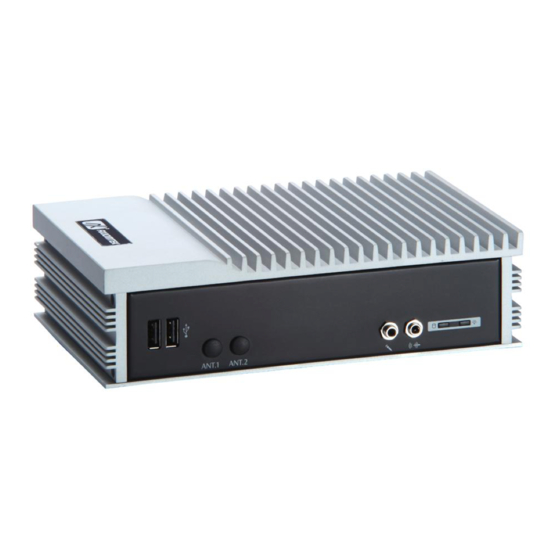
Page 17: I/O Outlets
Series User’s Manual I/O Outlets The following figures show you I/O outlets on front view of the eBOX621-801-FL. Front View Front View drawing Introduction... - Page 18 Series User’s Manual Rear View Rear View drawing Introduction...
-
Page 19: Packing List
Series User’s Manual Packing List The package bundled with your eBOX621-801-FL should contain the following items: eBOX621-801-FL System Unit x 1 eBOX621-801-FL Quick Manual x 1 CD x 1 (For Driver and User’s Manual) Screws pack x1 ... -
Page 20: Model List
Series User’s Manual Model List Capa801 with Dual Core Atom D525 (1.8GHz), GbE eBOX621-801-FL-D525- E36K621103 LAN*2, COM*3, USB*4, 9-34V DC-in, CF & HDD 1.8G-RC-US support If you cannot find this package or any items are missing, please contact Axiomtek distributors immediately. Introduction... -
Page 21: Chapter 2 Hardware Installation
Series User’s Manual CHAPTER 2 HARDWARE INSTALLATION The eBOX621-801-FL is convenient for your various hardware configurations, such as Memory Module, HDD (Hard Disk Drive), SSD (Solid State Drive) and CompactFlash card. The chapter 2 will show you how to install the hardware. -
Page 22: Installing The Memory Module
Series User’s Manual Installing the Memory Module Step 1 Turn off the system, and unplug the power cord. Step 2 Turn the system upside down to locate screws at the bottom, loosen screws. Step 3 Remove the bottom cover and Loosen screws of HDD bracket... - Page 23 Series User’s Manual Step 4 Remove the HDD bracket Step 5 Take out the thermal pad from accessory kit Hardware Installation...
- Page 24 Series User’s Manual Step 6 Remove the transparent plastic Mylar from thermal pad, and stick the thermal pad onto motherboard. Step 7 Locate the memory module, insert the gold colored contact into the socket. Hardware Installation...
- Page 25 Series User’s Manual Step 8 Push the module down, until it is firmly seated by locking two latches on the sides. Step 9 Take 2 thermal pad, remove the transparent plastic mylar and stick it onto memory. Hardware Installation...
- Page 26 Series User’s Manual Step 10 Fasten screws of HDD bracket Step 11 Close the cover to the chassis, and fasten all s crews. Hardware Installation...
-
Page 27: Installing The Sata Hdd
Series User’s Manual Installing the SATA HDD Step 1 Turn off the system, and unplug the power cord. Step 2 Turn the system upside down to locate screws at the Bottom, loosen screws. Step 3 Remove the bottom cover and Loosen screws of HDD bracket... - Page 28 Series User’s Manual Step 5 Remove the HDD bracket Step 6 Assembly the HDD bracket together with the SATA HDD Hardware Installation...
- Page 29 Series User’s Manual Step 7 Connect SATA cable and power cable to SATA HDD. Hardware Installation...
- Page 30 Series User’s Manual Step 8 Fasten screws of HDD bracket Step 9 Close the cover to the chassis, and fasten all screws. Hardware Installation...
-
Page 31: Installing The Compactflash
Series User’s Manual Installing the CompactFlash Step 1 Turn off the system, and unplug the power cord. Step 2 Turn the system upside down to locate screws at the Bottom, loosen screws. Step 3 Loosen screws to remove the CF cover. - Page 32 Series User’s Manual Step 5 Slide CF card into CF slot with caution. Step 6 Bend the CF Mylar with caution. Step 7 Close the cover to the chassis, and fas ten all screws. Hardware Installation...
-
Page 33: Installing The Express Mini Card
Series User’s Manual Installing the Express Mini Card Step 1 Turn off the system, and unplug the power cord. Step 2 Turn the system upside down to locate screws at the Bottom, loosen screws. Step 3 Loosen screws at left side and right side. There are Total 8 screws. - Page 34 Series User’s Manual Step 4 Remove the top heat sink to locate the Express Mini Card slot. Step 5 Slide Mini card into Mini Card slot with caution and Fasten screw of Express Mini Card. Step 6 Assembly the Top Cover back and fasten all screws.
-
Page 35: Installing The Wall Mount (Optional)
Series User’s Manual Installing the Wall Mount (Optional) The eBOX621-801-FL provides Wall Mount that customers can install as below: Step 1 Prepare Wall Mount assembling components (screws and Bracket) ready. Hardware Installation... - Page 36 Series User’s Manual Step 2 Loose the screw of four footpads at the bottom of eBOX621-801-FL and remove footpad. Hardware Installation...
- Page 37 Series User’s Manual Step 3 Fix the wall mount to the correct location, and fasten all screws. Hardware Installation...
-
Page 38: Installing The Vesa Mount (Optional)
Series User’s Manual Installing the VESA Mount (optional) The eBOX621-801-FL provides VESA Mount that customers can install as below: Step 1 Prepare VESA Mount assembling components (screws and VESA mount bracket) ready. Step 2 Loose the screw of four footpads at the bottom of eBOX621-801-FL, and emove footpad. - Page 39 Series User’s Manual Step 3 Decide correct mounting direction.eBOX621-801-FL supports both 100x100mm and 75x75mm VESA mount. The 100x100mm type has special direction. 100x100mm 75x75mm Hardware Installation...
- Page 40 Series User’s Manual Step 4 Fix the VESA mount to the correct location, and fasten all screws. Hardware Installation...
-
Page 41: Installing The Din-Rail Mount (Optional)
Series User’s Manual Installing the Din-Rail Mount (optional) The eBOX621-801-FL provides Din-Rail Mount that customers can install as below: Step 1 Prepare Din-Rail Mount assembling components (screws, Din-rail and VESA mount bracket) ready. Hardware Installation... - Page 42 Series User’s Manual Step 2 Loose the screw of four footpads at the bottom of eBOX621-801-FL and remove footpad. Step 3 Fix the VESA mount to the correct location, and fasten all screws. Hardware Installation...
- Page 43 Series User’s Manual Step 4 Fix the Din-rail mount bracket to the correct location, and fasten all screws. Hardware Installation...
- Page 44 Series User’s Manual MEMO: Hardware Installation...
-
Page 45: Chapter 3 Jumper Setting & Connector
Series User’s Manual CHAPTER 3 Jumper Setting & Connector Proper jumper settings configure the eBOX621-801-FL to meet your application purpose. We are herewith listing a summary table of all jumpers and default settings for onboard devices, respectively. Jumper Setting & Connector... -
Page 46: Sbc Layout
Series User’s Manual SBC layout TOP Side Jumper Setting & Connector... - Page 47 Series User’s Manual Bottom Side NOTE: We strongly recommended that you should not modify any unmentioned jumper setting without Axiomtek FAE’s instruction. Any modification without instruction might cause system to become damage. Jumper Setting & Connector...
-
Page 48: Jumper Setting Summary
Series User’s Manual Jumper Setting Summary Proper jumper settings configure the eBOX621-801-FL to meet your application purpose. We are herewith listing a summary table of all jumpers and default settings for onboard devices, respectively. Jumper Function / Default Setting Jumper Setting Compact Flash Voltage Selection Default: 3.3V... -
Page 49: Com1 Mode Select Jumpers (Jp4, Jp5, Jp6)
Series User’s Manual 3.2.2 COM1 Mode Select Jumpers (JP4, JP5, JP6) These jumpers select the communication mode of COM1 port to operate RS-232 or RS- 422 or RS-485.W hen these jumpers are selected to operate RS -422 or RS485, please make sure the COM1 is on Data mode. -
Page 50: Audio Output Jumper (Jp13)
Series User’s Manual 3.2.4 Audio Output Jumper (JP13) This jumper is to select which source for the audio output. W hen the Speaker Out is set, it delivers 2W /channel continuous into 8 Ohm loads. Description Function Jumper Setting... -
Page 51: Connectors
Series User’s Manual Connectors Connectors connect the system with other parts/devices. Loose or improper connection might cause problems. Make sure all connectors are properly and firmly connected. Below summary table shows you all connectors on the eBOX621-801-FL. External Connectors... -
Page 52: Serial Port Connector
Series User’s Manual 3.3.2 Serial Port Connector The system has three serial ports. COM1 is RS-232/422/485 port, and COM2 are RS- 232 port. Description DCD, Data Carrier Detect COM1 RXD, Receive Data TXD, Transmit Data DTR, Data Terminal Ready... -
Page 53: Vga Connector
Series User’s Manual 3.3.3 VGA Connector The VGA connector is a slim type 15-pin D-Sub connector which is common for the CRT VGA display. The VGA interface configuration can be configured via the software utility. Signal Signal Signal Green Blue N.C. -
Page 54: Usb Connector
Series User’s Manual 3.3.5 USB Connector These ports can be routed to UHCI controller #1 or EHCI controller #1. Signal USB Port 0 Signal USB Port 1 USB VCC USB VCC (+5V level) (+5V level) 5 6 7 8... -
Page 55: Sata Connector
Series User’s Manual 3.3.8 SATA Connector The SATA connector is for high-speed SATA interface ports and they can be connected to hard disk devices. Signal SATA_TX+ SATA_TX- SATA_RX- SATA_RX+ 3.3.9 SATA Power Connector The SATA connector is for high-speed SATA interface ports and they can be connected to hard disk devices. -
Page 56: Compactflash™ Socket
Series User’s Manual 3.3.10 CompactFlash™ Socket The system is equipped with a CompactFlash type-II socket with DMA mode to support an IDE interface CompactFlash disk. The socket is designed to avoid incorrect installation of the CompactFlash disk card. W hen installing or removing the CompactFlash disk card, please make sure the system power is off. -
Page 57: Ddr3 Sodimm Socket
Series User’s Manual 1 2 3 4 5 6 7 8 9 10 11 12 13 14 15 16 17 18 19 20 21 22 23 24 26 27 28 29 30 31 32 33 34 35 36 37 38 39 40 41 42 43 44 45 46 47 48 49 3.3.11 DDR3 SODIMM Socket... -
Page 58: Express Mini Card Slot
Series User’s Manual 3.3.12 Express Mini Card Slot PCI Express Mini Card connector supports a PCI Express x1 link and a USB 2.0 link. A PCI Express Mini Card can be applied to either PCI Express or USB 2.0. The USB 2.0 support will be helpful during the transition to PCI Express, because peripheral vendors will need time to design their chipsets to have the PCI Express function. - Page 59 Series User’s Manual Jumper Setting & Connector...
- Page 60 Series User’s Manual MEMO: Jumper Setting & Connector...
-
Page 61: Chapter 4 Ami Bios Setup Utility
Series User’s Manual CHAPTER 4 AMI BIOS SETUP UTILITY This chapter provides users with detailed description how to set up basic system configuration through the AMI BIOS setup utility. AMI BIOS Setup Utility... -
Page 62: Starting
Series User’s Manual Starting To enter the setup screens, follow the steps below: Turn on the computer and press the <Del> key immediately. After you press the <Delete> key, the main BIOS setup menu displays. You can access the other setup screens from the main BIOS setup menu, such as the Chipset and Power menus. -
Page 63: Navigation Keys
Series User’s Manual Navigation Keys The BIOS setup/utility uses a key-based navigation system called hot keys. Most of the BIOS setup utility hot keys can be used at any time during the setup navigation process. These keys include <F1>, <F10>, <Enter>, <ESC>, <Arrow> keys, and so on. -
Page 64: Main Menu
Series User’s Manual Main Menu W hen you first enter the Setup Utility, you will enter the Main setup screen. You can always return to the Main setup screen by selecting the Main tab. There are two Main Setup options. They are described in this section. The Main BIOS Setup screen is shown below. -
Page 65: Advanced Menu
Series User’s Manual Advanced Menu The Advanced menu allows users to set configuration of the CPU and other system devices. You can select any of the items in the left frame of the screen to go to the sub menus: ... - Page 66 Series User’s Manual Configure advanced CPU settings This screen shows the CPU Configuration, and you can change the value of the selected option. Execute-Disable Bit Capability This item helps you enable or disable the No-Execution Page Protection Technology.
- Page 67 Series User’s Manual IDE Configuration You can use this screen to select options for the IDE Configuration, and change the value of the selected option. A description of the selected item appears on the right side of the screen. For items marked with “”, please press <Enter> for more options.
- Page 68 Series User’s Manual Super IO Configuration You can use this screen to select options for the Super IO Configuration, and change the value of the selected option. A description of the selected item appears on the right side of the screen.
- Page 69 Series User’s Manual Hardware Health Configuration This screen shows the Hardware Health Configuration, which displays the temperature of System and Vlore, +12V, +5V, +3.3V. AMI BIOS Setup Utility...
- Page 70 Series User’s Manual ACPI Settings You can use this screen to select options for the ACPI Settings, and change the value of the selected option. General ACPI Configuration Scroll to this item and press <Enter> to view th e General ACPI Configuration sub menu, which contains General ACPI (Advanced Configuration and Power Management Interface) options for your configuration.
- Page 71 Series User’s Manual Suspend mode Allow you to select the Advanced Configuration and Power Interface (ACPI) state to be used for system suspend. Here are the options for your selection, S1 (POS), S3 (STR) and Auto. AMI BIOS Setup Utility...
- Page 72 Series User’s Manual AHCI Configuration USE this screen to select options for the AHCI Configuration and change the value of the selected option. AMI BIOS Setup Utility...
- Page 73 Series User’s Manual APM Configuration You can use this screen to select options for the APM Configuration, and change the value of the selected option. A description of the selected item appears on the right side of the screen.
- Page 74 Series User’s Manual Video Power Down Mode This option specifies the Power State that the video subsystem enters when the BIOS places it in a power saving state after the specified period of display inactivity has expired. The default setting is Suspend.
- Page 75 Series User’s Manual USB Configuration You can use this screen to select options for the USB Configuration, and change the value of the selected option. A description of the selected item appears on the right side of the screen.
-
Page 76: Boot Menu
Series User’s Manual Boot Menu The Boot menu allows users to change boot options of the system. You can select any of the items in the left frame of the screen to go to the sub menus: Boot Settings Configuration ... - Page 77 Series User’s Manual Boot Settings Configuration Quick Boot Enabling this item lets the BIOS skip some power on self-tests (POST). The default setting is Enabled. Boot Num-Lock Use this item to select the power-on state for the NumLock.. The default setting is On.
- Page 78 Series User’s Manual LAN Boot Option Use these items to enable or disable the Boot ROM function of the onboard LAN chip when the system boots up. Available options of the selected item appear on the right side of the screen ...
-
Page 79: Security Menu
Series User’s Manual Security Menu The Security menu allows users to change the security settings for the system. Supervisor Password This item indicates whether a supervisor password has been set. If the password has been installed,『 Installed』 displays. If not, 『Not Installed』displays. -
Page 80: Chipset Menu
Series User’s Manual Chipset Menu The Chipset menu allows users to change the advanced chipset settings. You can select any of the items in the left frame of the screen to go to the sub menus: North Bridge Configuration ... - Page 81 Series User’s Manual North Bridge Configuration Initiate Graphic Adapter When using multiple graphics cards, this item can select which graphics controller to be the primary display device during boot. Internal Graphics Mode Select This item allows you to select the amount of system memory used by the internal graphics device.
- Page 82 Series User’s Manual Video Function Configuration Press <Enter> for the sub-menu for setting up video function DVMT Mode Select Allow you to select DVMT (Dynamic Video Memory Technology) mode and Fixed Mode. DVMT/FIXED Memory Allow you to allocate a fixed amount of system memory as graphics memory. Here are the options for your selection, 128MB, 256MB and Maximum DVMT ...
- Page 83 Series User’s Manual Flat Panel Type Allow you to choose the resolution of the panel. AMI BIOS Setup Utility...
- Page 84 Series User’s Manual South Bridge Configuration HDA Controller This item allows you to enable or disabled the HD audio support. AMI BIOS Setup Utility...
-
Page 85: Exit Menu
Series User’s Manual Exit Menu The Exit menu allows users to load your system configuration with optimal or failsafe default values. Save Changes and Exit When you have completed the system configuration changes, select this option to leave Setup and reboot the computer so the new system configuration parameters can take effect. - Page 86 Series User’s Manual Load Fail-Safe Defaults It automatically sets all Setup options to a complete set of default settings when you select this option. The Fail-Safe settings are designed for maximum system stability, but not maximum performance. Select the Fail-Safe Setup options if your computer is experiencing system configuration problems.
-
Page 87: Appendix Awatchdog Timer
Series User’s Manual APPENDIX A WATCHDOG TIMER What is Watchdog Timer After the system stops working for a while, it can be auto -reset by the W atchdog Timer. The integrated W atchdog Timer can be set up in the system reset mode by program. - Page 88 Series User’s Manual al,01h dx,al ;Set Second or Minute : dx,2Eh al,0F5h dx,al dx,2Fh al,Nh ;N=00h or 08h(See below Note) dx,al ;Set base timer : dx,2Eh al,0F6h dx,al dx,2Fh al,Mh ;M=00h,01h,02h,..FFh (Hex),Value=0 to 255 dx,al ; (See below Note) ;Disable WDT:...
- Page 89 Series User’s Manual Note: When N’s value is 00h, the time base is set second. 00: Time-out Disable 01: Time-out occurs after 1 second 02: Time-out occurs after 2 seconds 03: Time-out occurs after 3 seconds FF: Time-out occurs after 255 seconds When N’s value is 08h, the time base is set minute.
- Page 90 Series User’s Manual MEMO: Watchdog Timer...
Need help?
Do you have a question about the eBOX621-801-FL Series and is the answer not in the manual?
Questions and answers