Page 1
MDI-4000 Series MDI-4000, MDI-4050, MDI-4100, MDI-4150 
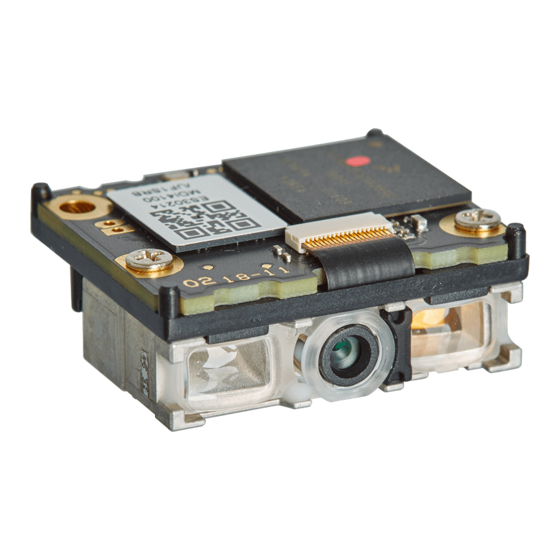
Low Profile, High-Performance, 2D Imager Engine Serial Interface Manual...
Page 2
Opticon assumes no liability for any direct, indirect, consequential or incidental damages arising out of use or inability to use both the hardware and software, even if Opticon has been informed about the possibility of such damages.
Page 3
MDI-4000 Series Serial Interface Manual Revision History Product Name: MDI-4000 Series Serial Interface Manual Edition Date Page Section Description of Changes February 28, 2020 Applied new template. Rewrote text for clarity. June 11, 2018 Initial release. Supported firmware: BD01J07...
MDI-4000 Series Serial Interface Manual Contents Overview ..........................1 MDI-4000 Series Scan Engine Features ..............1 Integration Flow ......................2 About the MDI-4000 Series Scan Engines ................. 3 Model Details ......................3 2.1.1 Standard Product Description ................3 2.1.2 Model Name Description ..................4 Scan Area ........................
Page 6
MDI-4000 Series Serial Interface Manual Interface ..........................19 UART ........................19 4.1.1 How to Switch to UART from USB ..............20 4.1.2 UART Interface Signal ..................20 4.1.3 UART Basic Information ..................21 4.1.4 Baud Rate (Transfer Speed) ................21 4.1.5 Character Format ....................21 4.1.6 Handshaking (Flow Control) ................22 4.1.7...
Page 7
MDI-4000 Series Serial Interface Manual Current Consumption ....................38 5.2.1 Absolute Maximum Ratings ................38 5.2.2 Recommended Operating Conditions ..............38 5.2.3 Peak Current Consumption ................38 5.2.4 Current Consumption of the MDI-4x00 ...............39 5.2.5 Current Consumption of the MDI-4x50 ...............40 Low Power .........................41 5.3.1...
Page 8
MDI-4000 Series Serial Interface Manual Setting Code Common Options .................55 6.2.1 GS1 Conversion ....................55 6.2.2 Positive and Negative Image of Barcodes (1D Code Common) ......57 6.2.3 Quiet Zone (1D Code Common) ................57 6.2.4 Redundancy (1D Code Common) ..............58 6.2.5 Add-On Waiting Time ..................58 6.2.6...
Page 9
MDI-4000 Series Serial Interface Manual How to Add Characters ....................84 7.2.1 How to Set the Prefix/Suffix ................84 7.2.2 Prefix/Suffix Commands ..................85 7.2.3 Prefix/Suffix Value Commands ................86 Read Options ........................90 Read Modes ......................90 8.1.1 Single and Multiple Read Modes ................90 8.1.2 Central Reading ....................91...
Page 10
MDI-4000 Series Serial Interface Manual Appendix ......................... 101 10.1 Code ID Table ......................101 10.1.1 Opticon Code ID Prefix/Suffix Value..............101 10.1.2 Code Option AIM/ISO15424 Code ID Prefix/Suffix Value ......... 102 10.2 MDI-4xx0 Specification Overview ................107 10.2.1 Common Specification Overview ..............107 10.2.2...
Page 11
Figure 9: Mirrored Image Configurations ....................16 Figure 10: Creating 1D Menu Barcodes with Opticon’s “UniversalConfig.” ..........18 Figure 11: Creating a 2D Menu Barcode with Opticon’s “UniversalConfig.” ..........19 Figure 12: Data Character Transfer Format ....................21 Figure 13: No Handshake ........................... 22 Figure 14: BUSY/READY ..........................
Page 12
MDI-4000 Series Serial Interface Manual...
Unless otherwise noted, all features apply to all models. 1.1 MDI-4000 Series Scan Engine Features The MDI-4000 Series includes a multitude of 2D scan engines to meet your needs. These low- profile, high-performance scan engines can be integrated into any product to perform high-end tasks.
107. 2. Download Tools Download the necessary tools from the Opticon website: • Opticon UniversalConfig: For configuration, image acquisition, and communication. • USB Driver: For USB-COM. • WIME: For COM output to HID output conversion. 3. Configure and Test the Scan Engine Evaluate the scan engine settings in your scanning environment and perform a read test: •...
MDI-4000 Series Serial Interface Manual 2 About the MDI-4000 Series Scan Engines Before configuring or using the MDI-4000 Series scan engines, make sure that you are familiar with their physical details and specifications. 2.1 Model Details The scan engine model is a combination of the model name, focus, and interface.
MDI-4000 Series Serial Interface Manual 2.1.2 Model Name Description The model name indicates the shape of the scan engine. The shape describes whether the decoder board is separate from or mounted to the camera, as well as whether low-power consumption mode is installed.
Confirm the connection: Connects the scan engine to the host through an RS-232C or USB interface and monitors each signal in the connection. • Confirm communications and barcode reading: Uses a terminal emulator or the Opticon UniversalConfig tool to confirm communications and barcode reading. •...
MDI-4000 Series Serial Interface Manual Figure 3: MEK-3100 Evaluation Board Figure 4: MEK-3100 Evaluation Board Kit 3 Configuration This chapter explains the scan engine configuration, default setting and saving setting, and basic commands. 3.1 How to Configure the Scan Engine with Commands You can configure the scan engine by sending commands through the serial interface or by reading 1D or 2D menu labels.
<ESC>[ΔΔΔ<CR> Two 4-digit commands <ESC>ΔΔΔΔ<CR> 2-digit and 3-digit command <ESC>ΔΔ[ΔΔΔ<CR> You can send the command through Opticon’s “UniversalConfig.” For help, contact your Opticon Sales Representative. Note: In UniversalConfig, <ESC> is automatically sent. Figure 5: Opticon’s “Universal Config” 3.1.2 Sending Command Packets The maximum length of a command packet is 1000 characters.
Page 20
MDI-4000 Series Serial Interface Manual Power Mode UART Baud Rate [bps] (UART) 9600 19200 38400 57600 115200 230400 460800 921600 Standby “How to Recover from Low Power Mode” on page Low Power For more information, see Standby If you are sending “Null” characters, send these characters first and wait at least 10 ms to send the command.
MDI-4000 Series Serial Interface Manual 3.2 Precautions for Sending Command Packets Startup Settings Power on/Reset *1*2 Stored in flash Copy the startup settings [EFY command Serial command to active settings Changes one or Changes one or more active settings more settings...
MDI-4000 Series Serial Interface Manual Settings Descriptions Setting Description Active Settings Contains the current active settings. The scan engine operates according to these settings. Active Settings include settings loaded from another areas, as well as new settings added through serial commands or menu labels.
MDI-4000 Series Serial Interface Manual 3.2.3 Custom Settings To save Active Settings to Custom Settings, send the [BAQ command at the end of command packet you want to save. To save Custom Settings and Active Settings at same time, send the [BAQZ2 command.
Page 24
MDI-4000 Series Serial Interface Manual Example Custom Command Line Settings Setting Command Enable Fast Boot Mode. [EFXQ1 ACK/NAK. Enable 2D Menu Barcode. [D1Z Disable Upside Down Image. [EFV[E8I Enable Set Baud Rate to 115200 bps. Enable Low Power Standby. [EB8 Set Low Power Standby Transition Time to 2 seconds.
MDI-4000 Series Serial Interface Manual Boot Time Specification (IF: UART/USB, VCC = 3.3V, 5.0V TA = 25°C) Mode Description Min. Typ. Max. Unit Normal Boot Time taken to be ready after supplying the power Fast Boot Mode Startup Settings * 1 * 2...
MDI-4000 Series Serial Interface Manual 3.5.2 Diagnostic Commands These commands can be used to get diagnostics information from the scan engine. Diagnostics Commands Command Description Notes Transmit software version Transmit settings The Z3 output result is subject to change when the firmware version is changed.
MDI-4000 Series Serial Interface Manual 3.5.5 Enable/Disable 2D Menu Barcodes Use these settings to enable or disable decoding 2D menu barcodes. When you are not using 2D menu barcodes, you should disable this setting. Enable/Disable 2D Menu Barcodes Command Description Notes ✓...
MDI-4000 Series Serial Interface Manual 3.5.8 Reading Operation Use these settings to enable or disable the reading operation. When reading is disabled, auto trigger and the TRIGn signal operation are invalid. Also, menu labels cannot be read. That is, only commands through serial communication are supported.
MDI-4000 Series Serial Interface Manual You can use Opticon’s “UniversalConfig” to create the 1D menu barcodes. For help, contact your Opticon Sales Representative. Print Figure 10: Creating 1D Menu Barcodes with Opticon’s “UniversalConfig.” 3.7 How to Configure the Scan Engine with a 2D Menu Barcode A 2D menu barcode can contain multiple settings that are processed in order in a single operation.
MDI-4000 Series Serial Interface Manual You can use Opticon’s “UniversalConfig” to create the 2D menu barcode. For help, contact your Opticon Sales Representative. Print Figure 11: Creating a 2D Menu Barcode with Opticon’s “UniversalConfig.” 3.8 Forced Initialization If the scan engine is unresponsive, you can force the scan engine to initialize.
MDI-4000 Series Serial Interface Manual 4.1.1 How to Switch to UART from USB When you change the interface to UART from USB, the configuration change persists through a firmware update. Use one of these methods to change the serial interface to UART from USB: •...
MDI-4000 Series Serial Interface Manual 4.1.3 UART Basic Information These are the basic UART Settings. UART Settings Setting Description Default Transfer speed 300 to 115200 bps 9600 bps Data length 7/8 bits 8 bit Parity bit None/Even/Odd None Stop bit...
MDI-4000 Series Serial Interface Manual Use these commands to set the number of data bits, type of parity bit, and number of stop bits. To activate and save the new configuration, you need to use the Z2 command (save settings in non-volatile memory).
MDI-4000 Series Serial Interface Manual BUSY/READY The scan engine and the host system notify each other when they are ready to receive data (BUSY/READY) through their RTS line. When they are connected (as shown in the next diagram), the CTS line can be used to check if the other side is busy (off) or ready to receive data (on).
MDI-4000 Series Serial Interface Manual To activate and save the new configuration, you need to use the Z2 command (save settings in non-volatile memory). CTS Timeout Commands Command Flow Control Timeout Default ✓ Indefinitely 100 ms 200 ms 400 ms Modem Link As soon as power is supplied to the scan engine, the scan engine’s RTS line is OFF.
MDI-4000 Series Serial Interface Manual ACK/NAK No Response ACK/NAK No Response is different from ACK/NAK mode in that if no response is received from the host within 100 ms, the scan engine assumes that the data has been successfully received by the host.
MDI-4000 Series Serial Interface Manual 4.1.8 Troubleshooting UART Use this table to find possible solutions to common UART problems. UART Troubleshooting Problem Possible Solutions • Cannot communicate Make sure communication settings, such as transfer speed and character format, are correct.
MDI-4000 Series Serial Interface Manual 4.2.2 USB-COM Interface Signal An IRISO Electronics Co., Ltd. 9681-12(12PIN) (bottom contact) equivalent connector is used. Name Function Conditions State Notes TRIGn Trigger L: Start operation 100kΩ pull up AIM/WAKEn Recovery signal L: Recover from...
Internet. If you are running Linux, the driver should already be installed. Download the USB Driver 1. Go to the Downloads page on the Opticon website at: https://opticon.com/downloads/. 2. Scroll down until you see the Software column on the right.
MDI-4000 Series Serial Interface Manual 3. Expand Ports (COM & LPT). All ports recognized by the PC are listed. 4. Make sure the Opticon USB Code Reader appears in the list of ports. 4.2.6 Fixed USB-COM Port This option enables a fixed USB-COM Port number. The COM port number assigned to the USB connected Windows PC will always be the same port number.
MDI-4000 Series Serial Interface Manual WIME may be able to resolve issues when multi-byte characters are not correctly output with USB-HID. Windows PC Scan Engine Output to focused application USB-COM as character information Communication Figure 21: COM to HID Output Through WIME 4.2.9...
MDI-4000 Series Serial Interface Manual 4.3.1 How to Switch to USB-HID When you change the interface to USB-HID, the configuration change persists through a firmware update. Use one of these methods to change the serial interface to USB-HID: • Send this command: [X.ZSU[X.ZZ2...
MDI-4000 Series Serial Interface Manual 4.3.3 USB-HID Basic Information These are the basic USB-HID settings. USB-HID Settings Setting Description Notes USB2.0 Full Speed Required power supply 500 mA Differs from actual power capacity consumption. Vendor ID 065 A Product ID...
MDI-4000 Series Serial Interface Manual 4.3.5 NumLock Control and CapsLock Control You can configure the behavior of NumLock and CapsLock when you send data. NumLock Control and CapsLock Control Commands Setting Command Description Initial Setting ✓ NumLock Numeric value does not use numeric keypad...
MDI-4000 Series Serial Interface Manual 4.3.7 Inter Character Delay (USB-HID) Inter character delay adds a configurable delay after each transmitted character. This delay can be helpful if the host does not support flow control and is not capable of handling the received data.
MDI-4000 Series Serial Interface Manual Keyboard Language Commands (continued) Command Description Code Page Default [BPJ Turkish Windows 1254 [EF4 Russian English Windows 1251 [EF5 Russian Cyrillic Windows 1251 [BAZ Brazilian Windows 1252 [E76 Chinese Windows 1252 [E77 Korean Windows 1252...
MDI-4000 Series Serial Interface Manual during the data output. When buffer mode is disabled, the scan engine stops other operations until it finishes outputting decoded data. Data Buffer Mode Commands Command Description Default [D80 Data buffer disable ✓ [D81 Data buffer enable *...
MDI-4000 Series Serial Interface Manual Power Mode Descriptions Status Description Read The scan engine is reading a barcode. Both the white LED and the green aiming light are on. Standby The scan engine is ready to read a barcode. Low Power The scan engine is in a low power consumption state.
MDI-4000 Series Serial Interface Manual 5.2.4 Current Consumption of the MDI-4x00 UART = 3.3V] (IF:UART, T = 25°C) Item State Recovery Symbol Conditions Min. Typ. Max. Unit Time Operating Read Current Standby Standby 0 ms Current 18 ms Configured Power = 5.0V]...
43 ms Configured Current Power Recovery time is time until ready to scan. Current value when USB is in “Selective Suspend” mode. When using the USB as virtual COM (USB-COM), use this USB driver: “Opticon USB Code Reader driver” version 3.x.x.x.
MDI-4000 Series Serial Interface Manual 5.3 Low Power Low power mode helps to further reduce power consumption when the scan engine is in standby mode. When the scan engine shifts from standby mode to low power mode, all scan engine settings are retained.
USB-COM (using the USB as a virtual COM) and USB-HID (using the USB for key code input) communications. Set Selective Suspend for USB-COM 1. Install the Opticon USB Code Reader driver Version 3.0.0.0 or later. 2. Enable USB Selective Suspend. Set Selective Suspend for USB-HID 1.
MDI-4000 Series Serial Interface Manual Scan Engine USB Host Recovery signal or command Remote wakeup Resume (SOF, Token, etc.) Successful reading Data USB bus shifted to SUSPEND state Selective suspend Figure 24: USB Low Power Mode Communication Sequence 5.4 How to Recover from Low Power Mode To recover from low power mode, you need to consider conditions such as the signal to use and “Low Power”...
MDI-4000 Series Serial Interface Manual High TRIGn RTS (*1) High POWERDWN Command acceptable 10 ms - Wave form * Configured State Read Low Power Low Power Recovery Standby Cannot be used when Handshaking is set to MODEM, because the RTS signal is “High.”...
MDI-4000 Series Serial Interface Manual 5.4.2 Recover from Low Power Mode by Command (UART) You can use a command to recover from low power mode. Recover from Low Power Mode by Command 1. To start the recovery process, send dummy data, such as a NULL character.
MDI-4000 Series Serial Interface Manual 5.4.3 Recover from Low Power Mode (USB) You can use a signal (TRIGn, CTS, and AIM/WAKEn) or a command to recover from low power mode. Recovery starts when the host starts sending a command through USB. Approximately 43 ms after the command is sent, the scan engine becomes active and is ready to read barcodes.
MDI-4000 Series Serial Interface Manual 5.5 Power ON /OFF Timing The power on/off timing of the scan engine is described below. 5.5.1 Power-On Timing Power-on timing indicates the time from power on until barcodes are readable. High TRIGn High Command acceptable...
MDI-4000 Series Serial Interface Manual For MEK-3100 circuit configuration, 40 ms or more is required. Figure 29: Power-Off Timing When saving scan engine configurations, settings are stored in the scan engine: • when the Z2 command is sent. • after 1D or 2D menu barcodes are processed.
MDI-4000 Series Serial Interface Manual Read Timing Symbol Descriptions Symbol Description Min. Typ. Max. Unit GR_LEDn signal period BUZZERn signal period “Good Read LED” on page You can configure the GR_LEDn signal period. For more information, see “Buzzer” on page You can configure the BUZZERn signal period.
MDI-4000 Series Serial Interface Manual TRIGn TRIGn signal duration Read time option Scan time Figure 32: Start from TRIGn Signal End TRIGn TRIGn signal duration Read time option Scan time Figure 33: Start from TRIGn Signal Start 5.6.3 Command Trigger Control To read a command, start reading by sending the “Z”...
MDI-4000 Series Serial Interface Manual 5.6.4 Trigger Delay Set the Trigger Delay to start reading after a specified period of time. Trigger Delay Commands Command Description Default [DEC Trigger delay time (1000a+100b+10c+d [s]) 0 ms TRIGn “Z” Command USB+ Trigger delay...
MDI-4000 Series Serial Interface Manual 6.2 Setting Code Common Options 6.2.1 GS1 Conversion The GS1 organization has defined fields (such as a serial number, production date, and price) that may be encoded in a barcode. These fields are identified by an application identifier (AI) followed by the data for that field.
GS characters. If the interface is set to USB-HID, the GS characters are transmitted as <CTRL>]: ]C101950123456789033103000123 You can create more complex conversions of GS1 barcodes with Opticon’s “UniversalConfig” program by completely defining how the various application identifiers and data are output. Figure 37: GS1 Edit Feature in Opticon’s “UniversalConfig”...
MDI-4000 Series Serial Interface Manual 6.2.2 Positive and Negative Image of Barcodes (1D Code Common) Barcodes are typically printed in black on a white background and are called normal or positive barcodes. But, sometimes they are printed in white on a black background, which are called negative barcodes.
MDI-4000 Series Serial Interface Manual 6.2.4 Redundancy (1D Code Common) When redundancy is enabled, a 1D code must be scanned and decoded multiple times with the same result before it is considered correctly decoded. The redundancy count is the number of times the code must be scanned in addition to the first scan.
MDI-4000 Series Serial Interface Manual 6.2.6 ECI Protocol Output Lets you determine whether to output data for ECI (Extended Channel Interpretation) protocol. ECI is an embedded piece of information in a barcode that tells the scan engine details about the references used to encode the data in the symbol. The scan engine uses this information to automatically select matching options to decode the symbol.
MDI-4000 Series Serial Interface Manual Configure OCR 1. Start the Opticon UniversalConfig application and click OCR. 2. Configure the appropriate OCR settings, and click OK. 3. Scan the configuration barcode. Note: For advanced settings, see the “Data Edit Programing Manual”. To configure settings that cannot be set, contact your local Opticon Representative.
Page 73
MDI-4000 Series Serial Interface Manual UPC-A Settings Setting Options Character set Numeric (0 - 9) Number of digits 12 digits (11 digits plus a 1-digit CD) fixed length CD method Modulus 10/Wait 3 UPC-A Transfer Data Format Digit Description Leading "0"...
Page 74
MDI-4000 Series Serial Interface Manual “0” Transfer” on page 62. UPC-A CD Transfer/Front 6.3.1.2 UPC-A Add-On 2 Digits/5 Digits UPC-A Add-On 2 Digits/5 Digits is a UPC-A barcode with an additional 2-digit or 5-digit barcode to the right of the main barcode. When add-on digits are enabled, the add-on code must be within the reading range for the barcode to be successfully read.
Page 75
MDI-4000 Series Serial Interface Manual 6.3.1.3 UPC-A CD Transfer/Front “0” Transfer Lets you determine whether to transmit a leading “0” and a check digit (CD). Because the 13-digit transfer data format transfers a leading “0” and a CD, the format is compatible with JAN/EAN-13.
MDI-4000 Series Serial Interface Manual 6.3.1.6 UPC-E CD Transfer/Front “0” Transfer Lets you transmit a leading “0” and a check digit (CD). Because the 8-digit transfer data format transfers a leading “0” and CD, the format is compatible with JAN/EAN-8.
Page 77
MDI-4000 Series Serial Interface Manual EAN/JAN-13 Settings Setting Options Character set Numeric (0 - 9) Number of digits 13 digits (12 digits plus a 1-digit CD) fixed length EAN/JAN-13 Transfer Data Format Digit Description Data 12 digits Check Digit (CD) 1 digit 6.3.2.1...
Page 78
MDI-4000 Series Serial Interface Manual ISBN Conversion When ISBN conversion is enabled, EAN-13 data with a leading “978” or “979” is converted. To re-calculate the CD, ISBN conversion removes the leading 3 digits and outputs the remaining 10 digits. If the CD is 10, ISBN conversion outputs “X.”...
Page 79
MDI-4000 Series Serial Interface Manual EAN/JAN-8 Add-On 2 Digits Transfer Data Format Digit Description Data 7 digits 1 digit Add-On 2 digits EAN/JAN-8 Add-On 5 Digits Transfer Data Format Digit Description Data 7 digits 1 digit Add-On 5 digits EAN/JAN-8 CD Transfer Lets you configure the EAN/JAN-8 check digit (CD).
MDI-4000 Series Serial Interface Manual EAN/JAN-8 Optional Settings Setting Command Description Default ✓ CD Transmission Transmit EAN/JAN-8 CD Do not transmit EAN/JAN-8 CD Add-on 2 digits Enable single EAN/JAN-8 Add-on 2 digits Add enable EAN/JAN-8 Add-on 2 digits [X4M Disable EAN/JAN-8 Add-on 2 digits...
Page 81
MDI-4000 Series Serial Interface Manual Code 39 Conversion Settings Setting Description Standard Code 39 Send data character as is. Full ASCII Code 39 Converts the correct combination of the data character to Full ASCII and transmits the data character. If an incorrect combination is found, the data character is not transmitted.
MDI-4000 Series Serial Interface Manual 6.3.4 Codabar Codabar is a relatively early stage barcode developed by Monarch Marking Company in 1972. Codabar Settings Setting Options Character set Numeric (0 - 9) Symbol (- $ :/, +) Start/stop code A, B, C, or D...
MDI-4000 Series Serial Interface Manual Start/Stop Code Transfer Lets you configure the transfer start/stop code. You can also convert the code and transfer the code when the start/stop code is transferred. Codabar Optional Settings Setting Command Description Default ✓ Do not check CD Check CD ✓...
MDI-4000 Series Serial Interface Manual Interleaved 2 of 5 Transfer Data Format Digit Description Data Variable length Interleaved 2 of 5 CD Method Lets you configure the CD. This setting also configures the CD for Interleaved 2 of 5, Industrial 2 of 5, S-Code, and Matrix 2 of 5.
MDI-4000 Series Serial Interface Manual Code128 Settings Setting Options Character set ASCII128 character Function character (FNC1 – 4) Code set selection character (A, B, C, and Shift) Start/stop code Hidden character Start pattern: 3 types (A, B, and C) Stop pattern: 1type...
MDI-4000 Series Serial Interface Manual 6.3.8 MSI/Plessey Setting Command Description Default Do not check CD ✓ Check 1 CD = MOD 10 Check 2 CD = MOD 10/MOD 10 Check 2 CD = MOD 10/MOD 11 Check 2 CD = MOD 11/MOD 10...
MDI-4000 Series Serial Interface Manual 6.3.12 Korean Postal Authority Setting Command Description Default CD transmission CD transmit ✓ Do not transmit CD ✓ Transmit dash Transmit dash Do not transmit dash Upside down Upside down reading enabled reading ✓ Upside down reading disabled 6.3.13 GS1 DataBar...
MDI-4000 Series Serial Interface Manual GS1 DataBar Expanded Settings Setting Options Character set Capital/small character alphabet, numbers, 20 types of symbols, function character (FNC1) Digits 74 digits (numeric) and 41 digits (alphabet) Check sum* Modulus 211 Check sum is always checked, but not sent.
Page 89
MDI-4000 Series Serial Interface Manual GS1 Composite Settings Setting Options Character set ASCII value 0 - 127 (ISO 646) ASCII value 128 - 255 (ISO 8859, Alphabet No.1, Extend ASCII) When using ECI protocol, many other character sets are available. For more “...
MDI-4000 Series Serial Interface Manual 6.3.15 PDF417 PDF417 is a stack linear barcode developed by Symbol Technology Inc. and is used for international logistics, ID cards, and parts labels. PDF417 is standardized in ISO/IEC 15438:2006. PDF417 Settings Setting Options Character set ASCII value 0 to 127 (ISO 646) ASCII value 128 to 255 (ISO 8859-1, Alphabet No.1, Extended ASCII)
MDI-4000 Series Serial Interface Manual 6.3.16 QR Code QR Code (shortened from Quick Response Code) is a matrix type 2D barcode developed by DENSO WAVE INC. QR Code became popular in a wide range of fields due to its fast readability and relatively large storage capacity.
MDI-4000 Series Serial Interface Manual QR Code Settings Setting Options Character set 1) Numeric data (numbers 0-9) 2) Alphanumeric data (numbers 0-9, capital characters A-Z, 9 special characters: space, $, %, *, +, -, ., /, :) 3) 8 bit byte data (Latin character based on JIS X 0201, character set of 8 bit code for Katakana character.)
MDI-4000 Series Serial Interface Manual Data Matrix Settings Setting Options Character set ASCII value 0 to 127 (ISO 646) ASCII value 128 to 255 (ISO 8859-1, Alphabet No.1, Expand ASCII) When using ECI protocol, many other character sets are available. For more “...
Page 94
MDI-4000 Series Serial Interface Manual Aztec Code Settings Setting Options Character set ASCII value 0 to 127 (ISO 646) ASCII value 128 to 255 (ISO 8859-1, Alphabet No.1, Expand ASCII) When using ECI protocol, many other character sets are available. For more “...
MDI-4000 Series Serial Interface Manual ECI Protocol Output” on page 6.4 How to Set the Number of Characters to Read When you scan barcode labels that have a fixed-length, configure the scan engine to only scan the number of characters in the barcode. When properly configured, the scan engine rejects barcodes that are not the specified length.
MDI-4000 Series Serial Interface Manual 6.4.2 Command List: Fixed Length ON/Minimum/Maximum Length To set the length for each barcode, enter a command followed by a value. When you reset the settings, the current length for the barcode becomes the default.
MDI-4000 Series Serial Interface Manual 7.2 How to Add Characters You can add special characters that provide additional information to the beginning or end of a barcode. The output format depends on whether you add a prefix/suffix or a preamble/postamble.
Page 98
MDI-4000 Series Serial Interface Manual Example prefix/suffix setting: To set “C39:” as the prefix and “CR” and “LF” as the suffix for Code 39, send this command: <Esc>M40CQ3Q96AO41M1J<CR> Note: You can also set the prefix/suffix with a menu or 2D menu barcode.
Description ASCII Includes all 128 ASCII characters. Code identification The code identification is transmitted in OPTICON ID, ISO15424 standard, or AIM-ID. Code length The number of characters after the output format that are configured with “How to Set Code-Specific Options” on page...
Page 101
• is modifier character Example Code ID command: To add “<OPTICON Code ID>” to the all codes prefix, send this command: <Esc>RY$2<CR> 7.2.3.3 Code Length To add the code length, send a code length command with the command to set a prefix/suffix.
MDI-4000 Series Serial Interface Manual Code Coordinate Commands Command Description Default [DDX Code vertex coordinate [DDY Code center coordinate Vertexes output format: Center output format: where: • X: 1 to 3 digits • Y: 1 to 3 digits The range of the coordinates is: •...
MDI-4000 Series Serial Interface Manual Scan time output format: where: • T is flexible length. • ms is maximum string length, which is 4. TRIGn “Z” Command Data Scan Time Figure 42: Scan Time 8 Read Options You can configure read options, such as read modes, trigger settings, illumination and aiming, batch reading, and data editing.
MDI-4000 Series Serial Interface Manual barcode from being read twice, the scan engine saves the barcode data in memory (up to 20 barcodes). When subsequent barcodes are read, the scan engine compares the data with the data in memory and ignores the data if it has been previously read. This read mode can be helpful to prevent reading the same barcode twice.
MDI-4000 Series Serial Interface Manual Figure 43: Readable Positions in Central Reading Figure 44: Unreadable Positions in Central Reading 8.2 Manual Trigger/Trigger Repeat By default, the scan engine is in manual trigger mode. In manual trigger mode, you can enable the Trigger Repeat function.
MDI-4000 Series Serial Interface Manual Example for Trigger Repeat Synchronized with Read Time: “While trigger is pressed” “Trigger is released” “Output data” Example for Trigger Repeat with Read Time set to 1 second or more: “While trigger is pressed” “Press trigger again to start reading”...
MDI-4000 Series Serial Interface Manual 8.3.2 Auto Trigger Sensitivity You can configure the sensitivity of the scan engine to detect barcodes. Sensitivity is affected by environmental conditions, so you need to adjust this setting accordingly. Auto Trigger Sensitivity Commands Command...
MDI-4000 Series Serial Interface Manual 8.3.6 Detection Mode Lets you determine which mode to use to detect a barcode. • Green aiming detection: A barcode is detected when it falls within the green aiming light. Use this mode to scan barcodes indoors. In brighter environments, the scan engine may have difficulty detecting barcodes using this mode.
You can configure batch reading for fixed format barcodes. Note: The data edit/extract reading function is supported by the scan engine but is not available in “UniversalConfig2.0”. For help, contact your local Opticon Representative. Configure Batch Reading 1. Start the Opticon UniversalConfig application and click Multi label.
MDI-4000 Series Serial Interface Manual 2. Follow the instructions to configure batch reading settings for up to 4 barcodes. To configure additional settings, contact your local Opticon Representative. 9 Indicator Options You can configure options for the Buzzer and Good Read LED.
MDI-4000 Series Serial Interface Manual 9.1.2 Good Read Buzzer The good read buzzer sounds when a barcode is successfully read. You can enable or disable the buzzer, as well as configure the duration and tone of the buzzer. Good Read Buzzer Commands...
MDI-4000 Series Serial Interface Manual Read Timeout Buzzer Commands Command Description Default ✓ [EAP Disable read timeout buzzer [EAQ Enable read timeout buzzer 9.1.5 Intermediate Buzzer If a barcode is decoded but does not yet meet the conditions to output data, an intermediate buzzer sounds.
MDI-4000 Series Serial Interface Manual Good Read LED Commands Command Description Default Disable indicator [XTH Indicator duration: 60 ms [XT8 Indicator duration: 100 ms ✓ Indicator duration: 200 ms Indicator duration: 400 ms Indicator duration: 800 ms 9.2.2 Inverted Good Read LED In Good Read LED inverted mode, the GR_LEDn signal is inverted.
MDI-4000 Series Serial Interface Manual Indicator Timing Commands Command Description Default ✓ Before data transmission* After data transmission Both indicators are activated soon after the barcode is decoded. 10 Appendix This appendix contains reference data. 10.1 Code ID Table These tables list the Code IDs that can be added to the prefix or suffix.
MDI-4000 Series Serial Interface Manual 10.1.2 Code Option AIM/ISO15424 Code ID Prefix/Suffix Value AIM/ISO15424 Code ID Symbology Code ID Symbology Code ID UPC-A Telepen UPC-A +2 UK/Plessey UPC-A +5 Code 128 UPC-E GS1-128 UPC-E +2 Code 93 UPC-E +5 Code 11...
Page 116
MDI-4000 Series Serial Interface Manual Code 39 Option AIM/ISO15424 Code ID: A* Code Option ]AIM-ID Code Option ]AIM-ID Normal Code 39 (D5) Full ASCII Code 39 (D4) or Full ASCII Code 39 if pos. (+K) Do not check CD (C1)
Page 117
MDI-4000 Series Serial Interface Manual IATA Option AIM/ISO15424 Code ID: R* Code Option ]AIM-ID Code Option ]AIM-ID Do not check CD (4H) Do not check CD (4H) Transmit CD (4L) Do not transmit CD (4M) Check FC and SN only (4I) or...
Page 118
MDI-4000 Series Serial Interface Manual Code 11 Option AIM/ISO15424 Code ID: H*/X0 Code Option ]AIM-ID Code Option ]AIM-ID Check 1CDs (BLG) Check 1CDs (BLG) or Check auto 1 or 2CDs (BLI) or Check 2CDs (BLH) (length > 12) or Check auto 1 or 2CDs (BLI)
Page 119
MDI-4000 Series Serial Interface Manual Aztec Options AIM/ISO15424 Code ID: z* Code Option ]AIM-ID Code Option ]AIM-ID No structure/other Structured append header included, FNC1 following an initial FNC1 preceding 1st message letter or pair of digits character FNC1 following an initial letter or...
MDI-4000 Series Serial Interface Manual Maxi Code Option AIM/ISO15424 Code ID: U* Code Option ]AIM-ID Code Option ]AIM-ID Symbol in mode 4 of 5 Symbol in mode 4 of 5, ECI protocol implemented Symbol in mode 2 of 3 Symbol in mode 2 of 3, ECI protocol implemented 10.2 MDI-4xx0 Specification Overview...
MDI-4000 Series Serial Interface Manual Environmental Specifications Specification Value Notes Temperature Operating -20 to 60 °C AC adapter 0 to 40°C Storage -40 to 70 °C Humidity Operating 5 to 90% (non-condensing, no frost) Storage 5 to 90% (non-condensing, no frost)
Page 122
MDI-4000 Series Serial Interface Manual Standard Model (SR) Reading Depth of Field Resolution Symbology Guaranteed Value Typical Value mm (mil) (MRD) Near Near 0.127 mm Code 39 66 mm 112 mm 55 mm 128 mm (5 mil) (0.8) (2.6″) (4.4″) (2.1″)
Page 123
MDI-4000 Series Serial Interface Manual High-Density Model (HD) Reading Depth of Field = 25°C) Resolution Symbology Guaranteed Value Typical Value mm (mil) (MRD) Near Near 0.076 mm Code 39 55 mm 65 mm 47 mm 74 mm (3 mil) (0.8) (2.2″)
Page 124
MDI-4000 Series Serial Interface Manual Ultra High-Density Model (UD) Reading Depth of Field = 25°C) Resolution Symbology Guaranteed Value Typical Value mm (mil) (MRD) Near Near 0.076 mm Code 39 37 mm 58 mm 30 mm 67 mm (3 mil) (0.8)
MDI-4000 Series Serial Interface Manual 10.2.3 MDI-4xx0 Detailed View MDI-4100 and MDI-4150 Dimensions Dimensions: W: 25.3 mm × D: 21.0 mm × H: 9.7 mm Weight: Approx. 5.5 g Product Label 25.3 Camera Lens Aiming LED lens Illumination LED Lens 21.6...
MDI-4000 Series Serial Interface Manual MDI-4100 and MDI-4150 Circuit Board The MDI-4100 and MDI-4150 have different circuit board thicknesses. MDI-4100 MDI-4150 Figure 46: MDI-4100 and MDI-4150 Circuit Board...
MDI-4000 Series Serial Interface Manual MDI-4000 and MDI-4050 Detailed View Camera: Approx. 13.6 mm (D) × 24.6 mm (W) × 6 mm (H) Decoder Board: Approx. 20.8 mm (D) × 25.1 mm (W) × 3.2 mm (H) Weight: Approx. 5.5g...
MDI-4000 Series Serial Interface Manual DBM-4000 and DBM-4050 Decoder Board 25.1 ( 4.5 ) 21.4 IRISO(12pin) 9681-12 φ 2.3 Hole (1.7 ) MOLEX(19pin) 504281-1900 21.6 Height of the DBM-4000 and the DBM-4050. Figure 48: DBM-4000 and DBM-4050 Decoder Board DBM-4000 and DBM-4050 Circuit Board The DBM-4000 and DBM-4050 have different circuit board thicknesses.
MDI-4000 Series Serial Interface Manual FPC Cable Connected to JST 17FXVL-RSM1-GAN-TF(HF) (17pin) Shield area Connected to MOLEX 5042811900 (19pin) Figure 50: FPC Cable 10.3 Sample Barcodes 10.3.1 1D Barcodes UPC-A UPC-A +2 UPC-E UPC-A +5...
Page 130
MDI-4000 Series Serial Interface Manual UPC-E +5 UPC-E +2 EAN/JAN EAN/JAN-13 EAN/JAN-13 +2 EAN/JAN-13 +5 EAN/JAN-8 EAN/JAN-8 +2 EAN-8 +5 Code 39 Code 39 Code 39 Italian Pharmaceutical...
Page 131
MDI-4000 Series Serial Interface Manual Code 39 Full ASCII Tri-Optic Codabar Codabar Codabar ABC Codabar CX Industrial 2 of 5/Interleaved 2 of 5 Industrial 2 of 5 Interleaved 2 of 5 S-Code...
MDI-4000 Series Serial Interface Manual Code 128 Code 93 IATA MSI/Plessey UK/Plessey Telepen Code11 Matrix 2 of 5 10.3.2 Postal Code Chinese Post Matrix 2 of 5 Korean Postal Authority Intelligent Mail Barcode...
Page 133
MDI-4000 Series Serial Interface Manual POSTNET PLANET Japan Postal Netherland KIX Code Australian Postal UK Postal (Royal mail) 4-State Mailmark Barcode...
MDI-4000 Series Serial Interface Manual 10.3.5 2D Barcodes PDF417 Micro PDF417 Codablock F QR Code Micro QR Data Matrix(ECC 200) Aztec Code Aztec Runes Chinese-sensible code Maxi Code...
Need help?
Do you have a question about the MDI-4000 Series and is the answer not in the manual?
Questions and answers