
Subscribe to Our Youtube Channel
Related Manuals for SMC Networks EX600-DX Series


Summary of Contents for SMC Networks EX600-DX Series
- Page 1 No.EX##-OMN0036 Fieldbus system Digital unit PRODUCT NAME EX600-DX## EX600-DY## EX600-DM## MODEL/ Series...
-
Page 2: Table Of Contents
Table of Contents Safety Instructions System Outline Assembly Mounting and Installation Installation Wiring Digital input unit Model Indication and How to Order Names and Functions of Product Mounting and Installation Wiring LED Display Specification Specifications Dimensions Digital output unit Model Indication and How to Order Names and Functions of Product Mounting and Installation Wiring... - Page 3 Common items Maintenance Troubleshooting Parameter Setting I/O Map Diagnostic Accessories Precautions before mounting No.EX##-OMN0036...
-
Page 4: Safety Instructions
Safety Instructions These safety instructions are intended to prevent hazardous situations and/or equipment damage. These instructions indicate the level of potential hazard with the labels of "Caution", "Warning" or "Danger". They are all important notes for safety and must be followed in addition to International ∗1 ∗2 standards (ISO/IEC), Japan Industrial Standards (JIS) - Page 5 Caution 1. The product is provided for use in manufacturing industries. The product herein described is basically provided for peaceful use in manufacturing industries. If considering using the product in other industries, consult SMC beforehand and exchange specifications or a contract if necessary. If anything is unclear, contact your nearest sales branch.
- Page 6 Operator ♦This operation manual has been written for those who have knowledge of machinery and apparatus that use pneumatic equipment and have full knowledge of assembly, operation and maintenance of such equipment. ♦Please read this operation manual carefully and understand it before assembling, operating or providing maintenance to the product.
- Page 7 Caution When handling the unit or assembling/replacing units: ■ •Do not touch the sharp metal parts of the connector or plug for connecting units. •Take care not to hit your hand when disassembling the unit. The connecting portions of the unit are firmly joined with seals. •When joining units, take care not to get fingers caught between units.
- Page 8 ●Product handling ∗Installation •Do not drop, hit or apply excessive shock to the SI unit. Otherwise damage to the product can result, causing malfunction. •Tighten to the specified tightening torque. If the tightening torque is exceeded the mounting screws may be broken. IP67 protection cannot be guaranteed if the screws are not tightened to the specified torque.
- Page 9 •When a surge-generating load such as a relay, valve or lamp is driven directly, use a product with a built-in surge absorbing element. Direct drive of a load generating surge voltage can damage the unit. •The product is CE marked, but not immune to lightning strikes. Take measures against lightning strikes in the system.
-
Page 10: System Outline
System Outline •System configuration The EX600 range of units can be connected to various types of Fieldbus to realize the reduction of input or output device wiring and the distributed control system. The unit communicates with the Fieldbus through the SI unit. One SI unit can be connected with manifold valves with up to 32 outputs and the input • output • I/O units with maximum 10 units. -
Page 11: Assembly
Assembly •Composing the unit as a manifold ∗: If the unit was purchased as a manifold, the work described in this section is not necessary. (1)Connect the unit to the end plate. The Digital unit, Analog unit can be connected in any order. Tighten the bracket of the joint using tightening torque 1.5 to 1.6 Nm. - Page 12 (4)Mounting the valve plate. Mount the valve plate (EX600-ZMV□) to the valve manifold using the valve set screws. (M3x8) Apply 0.6 to 0.7 Nm tightening torque to the screws. Screw mounting place : 2 places S0700 : 2 places VQC1000: 2 places VQC2000: 3 places VQC4000: 4 places : 2 places...
-
Page 13: Mounting And Installation
Mounting and Installation ■Installation •Direct mounting (1)When joining six or more units, fix the middle part of the complete EX600 unit with an intermediate reinforcing brace (EX600-ZMB1) before mounting using 2-M4x5 screws. Tightening torque: 0.7 to 0.8 Nm. Intermediate reinforcing brace (EX600-ZMB1) (2)Fix and tighten the end plates at one end of the unit. - Page 14 •DIN rail mounting (Available for series other than SY series. Refer to the catalog for SY series.) (1)When joining six or more units, fix the middle part of the complete EX600 unit with an intermediate reinforcing brace (EX600-ZMB2) before mounting, using 2-M4x6 screws. Tightening torque: 0.7 to 0.8 Nm.
-
Page 15: Wiring
■Wiring •Connect the M12 or M8 connector cable. M12 connector is applicable for SPEEDCON connector. SPEEDCON connector wiring method is explained below. (1)Align the mark B on the metal bracket of the cable side connector (plug/socket) with the mark A. (2)Align the mark C on the unit and insert the connector into the unit vertically. - Page 16 •Spring type terminal connection method is explained below. -15- No.EX##-OMN0036...
- Page 17 The electric wire below can be connected to the terminal block connector. •Single conductor. •Stranded conductor. •Flexible stranded conductor (Stranded thin conductor). •Flexible stranded conductor with the ultrasonic welded. •Flexible stranded conductor with crimped ferrule. ●Precautions for handling •To open the clamp, use a flat blade screwdriver of blade width 2.5 mm, and thickness of 0.4 mm or less.
-
Page 18: Digital Input Unit
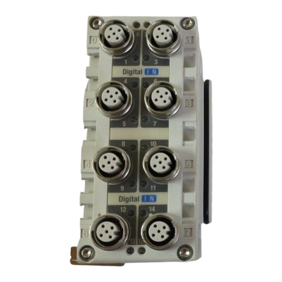
Digital input unit Model Indication and How to Order EX600-DX Digital input Connector, number of inputs and open circuit detection Open circuit Symbol Connector Number of inputs Input type detection ∗ Symbol Content 4xM12 connector (5 pin) 8 inputs 8xM8 connector (3 pin) 8 inputs 8xM8 connector (3 pin) 8 inputs... - Page 19 •EX600-DX C Description Function Status display LED Displays the status of the unit. Connector (Input) Connector for input device. Marker groove Groove to mount a marker. Joint bracket Bracket for joining to adjacent units. Unit connector (Plug) Transmits signals and power supplies to adjacent units. •EX600-DX D Description Function...
- Page 20 •EX600-DX E Description Function Status display LED Displays the status of the unit. Connector (Input) Connector for input device. Marker groove Groove to mount a marker. Lock screw Fixes D-sub connector. (No.4-40 UNC) Joint bracket Bracket for joining to adjacent units. Unit connector (Plug) Transmits signals and power supplies to adjacent units.
-
Page 21: Mounting And Installation
Mounting and Installation ■Wiring ○Connector pin assignment and circuit diagram (1)EX600-DX B/EX600-DX D •Connector pin assignment Configuration Pin number Signal name 24 V (Control and input) Input 2 0 V (Control and input) Input 1 ∗: An M12 connector (4 pin) can also be connected. •Circuit diagram •EX600-DXPB/EX600-DXPD •EX600-DXNB/EX600-DXND... - Page 22 (2)EX600-DX C •Connector pin assignment Configuration Pin number Signal name 24 V (Control and input) 0 V (Control and input) Input •Circuit diagram •EX600-DXPC •EX600-DXNC ∗1: Only for EX600-DXPC1. ∗2: Only for EX600-DXNC1. ●Precautions for handling Be sure to fit a seal cap on any unused connectors. Proper use of the seal cap enables the enclosure to achieve IP67 specification.
- Page 23 (3)EX600-DX E •Connector pin assignment Configuration Pin number Signal name Input 0 Input 2 Input 4 Input 6 Input 8 Input 10 Input 12 Input 14 24 V (Control and input) 0 V (Control and input) 0 V (Control and input) Input 1 Input 3 Input 5...
- Page 24 (4)EX600-DX F •Connector pin assignment Configuration Group Pin number Signal name 24 V (Control and input) X0 Input 0 Input 1 0 V (Control and input) X0 24 V (Control and input) X1 Input 2 Input 3 0 V (Control and input) X1 24 V (Control and input) X2 Input 4 Input 5...
- Page 25 •Circuit diagram •EX600-DXPF •EX600-DXNF -24- No.EX##-OMN0036...
-
Page 26: Led Display
LED Display The status display LED shows the following unit state. Various kinds of status can be checked as follows: •EX600-DX B /EX600-DX C Display Content The power supply for control and input, or the input device, is OFF. The input device is ON. - Page 27 •EX600-DX D Display Content The power supply for control and input, or the input device, is OFF. The input device is ON. Green LED is ON The power supply of either input device of adjoined up and down LED has a short circuit.
- Page 28 •EX600-DX E /EX600-DX F Display Content The power supply for control and input is OFF. ST LED is OFF The product is operating normally. Green LED is ON The power supply of input device has a short circuit. (Each of input 0 to 15) Red LED is ON The input device ON/OFF count has exceeded the set value.
-
Page 29: Specification
Specification ■Specifications Model EX600-DXPB EX600-DXNB EX600-DXPC EX600-DXNC EX600-DXPD EX600-DXND Input type ∗ 1 ∗ 1 Input connector M12 (5 pin) socket M8 (3 pin) socket M12 (5 pin) socket 8 inputs 8 inputs 16 inputs Number of inputs (2 inputs/connector) (1 input/connector) (2 inputs/connector) Powor supply... - Page 30 Model EX600-DXPE EX600-DXNE EX600-DXPF EX600-DXNF Input type D-sub (25 pin) socket Input connector Spring type terminal (32 pin) Lock screw: No.4-40 UNC Number of inputs 16 inputs Power supply voltage 24 VDC Class2, 2 A (Control and input) Max. sensor 0.5 A/group 2 A/unit supply current...
- Page 31 ○Digital input data The relationship between the connector position and the input data assignment is as shown in the table below. •Input signal assignment (EX600-DX B ) Connector number Connector position Pin 2 Bit 1 Bit 3 Bit 5 Bit 7 Input signal Pin 4 Bit 0...
-
Page 32: Dimensions
•Input signal assignment (EX600-DX F ) Group Terminal position Pin 2 Bit 0 Bit 2 Bit 4 Bit 6 Bit 8 Bit 10 Bit 12 Bit 14 Input signal Pin 3 Bit 1 Bit 3 Bit 5 Bit 7 Bit 9 Bit 11 Bit 13 Bit 15... - Page 33 •EX600-DX C •EX600-DX D -32- No.EX##-OMN0036...
- Page 34 •EX600-DX E •EX600-DX F -33- No.EX##-OMN0036...
-
Page 35: Digital Output Unit
Digital output unit Model Indication and How to Order EX600-DY Digital output Connector and number of outputs Symbol Connector Number of outputs ∗ Output type 4xM12 connector (5 pin) 8 outputs Symbol Content D-sub connector (25 pin) 16 outputs Spring type terminals (32 pin) 16 outputs ∗: An M12 connector (4 pin) can also be connected. - Page 36 •EX600-DY E Description Function Status display LED Displays the status of the unit. Connector (Output) Connector for output device. Marker groove Groove to mount a marker. Lock screw Fixes D-sub connector. (No.4-40 UNC) Joint bracket Bracket for joining to adjacent units. Unit connector (Plug) Transmits signals and power supplies to adjacent units.
-
Page 37: Mounting And Installation
Mounting and Installation ■Wiring ○Connector pin assignment and circuit diagram (1)EX600-DY B •Connector pin assignment Signal name Configuration Pin number EX600-DYPB EX600-DYNB 24 V (Output) Output 2 Output 2 0 V (Output) Output 1 Output 1 ∗: An M12 connector (4 pin) can also be connected. •Circuit diagram •EX600-DYPB •EX600-DYNB... - Page 38 (2)EX600-DY E •Connector pin assignment Signal name Configuration Pin number EX600-DYPE EX600-DYNE Output 0 Output 2 Output 4 Output 6 Output 8 Output 10 Output 12 Output 14 0 V (Output) 24 V (Output) Output 1 Output 3 Output 5 Output 7 Output 9 Output 11...
- Page 39 ●Precautions for handling Note the following points when using the open circuit detection: •This function detects open circuit only when the output is OFF. Therefore if output is turned ON, open circuit can not be detected. •Refer to the SI unit Operation Manual of protocol used for setting of the open circuit detection.
- Page 40 •Circuit diagram •EX600-DYPF •EX600-DYNF ●Precautions for handling Note the following points when using the open circuit detection: •This function detects open circuit only when the output is OFF. Therefore if output is turned ON, open circuit can not be detected. •Refer to the SI unit Operation Manual of protocol used for setting of the open circuit detection.
-
Page 41: Led Display
LED Display The status display LED shows the following unit state. Various kinds of status can be checked as follows: •EX600-DY B Display Content The power supply for control and input, or the output device, is OFF. The output device is ON. Green LED is ON The output device has a short circuit. - Page 42 •EX600-DY E/EX600-DY F Display Content The power supply for control and input is OFF. The product is operating normally. Green LED is ON The output device has a short circuit. (Each of output 0 to 15) Red LED is ON Either of the following conditions: •The output device ON/OFF count has exceeded the set value.
-
Page 43: Specification
Specification ■Specifications Model EX600-DYPB EX600-DYNB EX600-DYPE EX600-DYNE EX600-DYPF EX600-DYNF Output type Output D-sub (25 pin) socket ∗ 1 M12 (5 pin) socket Spring type terminal (32 pin) connector Lock screw: No.4-40 UNC Number of 8 outputs 16 outputs outputs (2 outputs/connector) Power supply voltage 24 VDC Class2, 2 A... - Page 44 ○Digital Output data The relationship between the connector position and the output data assignment is as shown in the table below. •Output signal assignment (EX600-DY B) Connector number Connector position Pin 2 Bit 1 Bit 3 Bit 5 Bit 7 Output signal Pin 4 Bit 0...
-
Page 45: Dimensions
■Dimensions •EX600-DY B •EX600-DY E -44- No.EX##-OMN0036... - Page 46 •EX600-DY F -45- No.EX##-OMN0036...
-
Page 47: Digital I/O Unit
Digital I/O unit Model Indication and How to Order EX600-DM Digital I/O Connector and number of I/O Input and Symbol Connector Number of inputs Number of outputs Output type D-sub connector (25 pin) 8 inputs 8 outputs Symbol Content Spring type terminals (32 pin) 8 inputs 8 outputs... - Page 48 •EX600-DM F Description Function Status display LED Displays the status of the unit. Connector (I /O ) Connector for input and output devices. Marker groove Groove to mount a marker. Joint bracket Bracket for joining to adjacent units. Unit connector (Plug) Transmits signals and power supplies to adjacent units.
-
Page 49: Mounting And Installation
Mounting and Installation ■Wiring ○Connector pin assignment and circuit diagram (1)EX600-DM E •Connector pin assignment Signal name Configuration Pin number EX600-DMPE EX600-DMNE Input 0 Input 1 Input 2 Input 3 Input 4 Input 5 Input 6 Input 7 24 V (Control and input) 24 V (Control and input) 0 V (Control and input) 0 V (Control and input) - Page 50 •Circuit diagram •EX600-DMPE •EX600-DMNE ●Precautions for handling Note the following points when using the open circuit detection: •This function detects open circuit only when the output is OFF. Therefore if output is turned ON, open circuit can not be detected. •Refer to the SI unit Operation Manual of protocol used for setting of the open circuit detection.
- Page 51 (2)EX600-DM F •Connector pin assignment Signal name Configuration Group Number EX600-DMPF EX600-DMNF 24 V (Control and input) X0 Input 0 Input 1 0 V (Control and input) X0 24 V (Control and input) X1 Input 2 Input 3 0 V (Control and input) X1 24 V (Control and input) X2 Input 4 Input 5...
- Page 52 •Circuit diagram •EX600-DMPF •EX600-DMNF ●Precautions for handling Note the following points when using the open circuit detection: •This function detects open circuit only when the output is OFF. Therefore if output is turned ON, open circuit can not be detected. •Refer to the SI unit Operation Manual of protocol used for setting of the open circuit detection.
-
Page 53: Led Display
LED Display The status display LED shows the following unit state. Various kinds of status can be checked as follows. •EX600-DM E/EX600-DM F Display Content The power supply for control and input is OFF. The product is operating normally. Green LEDs are ON The power supply of input device has a short circuit. - Page 54 Display Content The input device and the output device are OFF. (Each LED display number corresponds to input 0 to 7and output 0 to 7.) The input device is ON. (Each LED display number corresponds to input 0 to 7.) Input (left) “0 to 7”...
-
Page 55: Specification
Specification ■Specifications Model EX600-DMPE EX600-DMNE EX600-DMPF EX600-DMNF Input and output type D-sub (25 pin) socket Connector Spring type terminal (32 pin) Lock screw: No.4-40 UNC Number of inputs 8 inputs Power supply voltage 24 VDC Class2, 2 A (Control and input) Max. - Page 56 ○Digital I/O data The relationship between the connector position and the I/O data assignment is as shown in the table below. •I/O signal assignment (EX600-DM E) Configuration Pin number Signal Input Input Input Input Input Input Input Input name Input Bit 0 Bit 1 Bit 2...
-
Page 57: Dimensions
■Dimensions •EX600-DM E •EX600-DM F -56- No.EX##-OMN0036... - Page 58 Common items Maintenance Turn off the power supply, stop the supplied air, exhaust the residual pressure and verify the release of air before performing maintenance. Cleaning method Use a soft cloth to remove stains. For heavy stains, use a cloth soaked with diluted neutral detergent and fully squeezed, then wipe up the stains again with a dry cloth.
- Page 59 Troubleshooting Refer to the SI unit Operation Manual of protocol used. Parameter Setting Refer to the SI unit Operation Manual of protocol used. I/O Map Refer to the SI unit Operation Manual of protocol used. Diagnostic Refer to the SI unit Operation Manual of protocol used. Accessories Refer to the SI unit Operation Manual of protocol used.
- Page 60 Precautions before mounting The units that can be connected vary depending on the product number. Check the applicable unit type before mounting the unit. SI Unit EX600-SPR□ EX600-SPR□A (PROFIBUS DP) (PROFIBUS DP) EX600-SMJ□ EX600-SEN□ (CC-Link) (EtherNet/IP) EX600-SDN□ EX600-SDN□A (DeviceNet) (DeviceNet) EX600-DX□B ○...
- Page 61 Revision history Note: Specifications are subject to change without prior notice and any obligation on the part of the manufacturer. © 2010 SMC Corporation All Rights Reserved No.EX##-OMN0036...
Need help?
Do you have a question about the EX600-DX Series and is the answer not in the manual?
Questions and answers