
Related Manuals for SMC Networks EX600-SMJ Series


Summary of Contents for SMC Networks EX600-SMJ Series
- Page 1 No.EX##-OMN0034 Fieldbus system CC-Link compatible SI unit PRODUCT NAME EX600-SMJ# EX600-ED# MODEL/ Series...
-
Page 2: Table Of Contents
Table of Contents Safety Instructions System Outline Definition and terminology Assembly Basic precautions Mounting and Installation Installation Wiring SI Unit Model Indication and How to Order Names and Functions of Product Mounting and Installation Wiring Setting and Adjustment LED Display Specification Specifications Dimensions... -
Page 3: Safety Instructions
Safety Instructions These safety instructions are intended to prevent hazardous situations and/or equipment damage. These instructions indicate the level of potential hazard with the labels of "Caution", "Warning" or "Danger". They are all important notes for safety and must be followed in addition to International ∗1 ∗2 standards (ISO/IEC), Japan Industrial Standards (JIS) - Page 4 Caution 1. The product is provided for use in manufacturing industries. The product herein described is basically provided for peaceful use in manufacturing industries. If considering using the product in other industries, consult SMC beforehand and exchange specifications or a contract if necessary. If anything is unclear, contact your nearest sales branch.
- Page 5 Operator ♦This operation manual has been written for those who have knowledge of machinery and apparatus that use pneumatic equipment and have full knowledge of assembly, operation and maintenance of such equipment. ♦Please read this operation manual carefully and understand it before assembling, operating or providing maintenance to the product.
- Page 6 Caution When handling the unit or assembling/replacing units: ■ •Do not touch the sharp metal parts of the connector or plug for connecting units. •Take care not to hit your hand when disassembling the unit. The connecting portions of the unit are firmly joined with seals. •When joining units, take care not to get fingers caught between units.
- Page 7 ●Product handling ∗Installation •Do not drop, hit or apply excessive shock to the SI unit. Otherwise damage to the product can result, causing malfunction. •Tighten to the specified tightening torque. If the tightening torque is exceeded the mounting screws may be broken. IP67 protection cannot be guaranteed if the screws are not tightened to the specified torque.
- Page 8 •When a surge-generating load such as a relay, valve or lamp is driven directly, use a product with a built-in surge absorbing element. Direct drive of a load generating surge voltage can damage the unit. •The product is CE marked, but not immune to lightning strikes. Take measures against lightning strikes in the system.
-
Page 9: System Outline
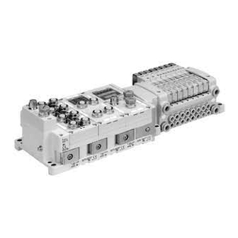
System Outline •System configuration The EX600 range of units can be connected to various types of Fieldbus to realize the reduction of input or output device wiring and the distributed control system. The unit communicates with the Fieldbus through the SI unit. One SI unit can be connected with manifold valves with up to 32 outputs and the input • output • I/O units with maximum 10 units. -
Page 10: Definition And Terminology
■Definition and terminology Terminology Definition The signal from the analog input device is converted to digital, and displayed in decimal AD value and hexadecimal. These hexadecimal and decimal values are also outputted to the analog output device. The speed at which the fieldbus sends and receives data. It depends on higher-level Communication speed equipment (PLC, etc.) and is measured in bps (Bits per second). - Page 11 Terminology Definition A diagnosis function to detect an over current due to the short circuit of the output Short circuit detection and/or power supply positive line with respect to the GND line. A function to protect the internal circuit from being broken by an over current due to the Short circuit protection short circuit of the output and/or power supply positive line with respect to the GND line.
-
Page 12: Assembly
Assembly ■Basic precautions The units that can be connected vary depending on the Handheld Terminal product number. Product number of the Handheld Terminal Units that can be assembled EX600-HT1 EX600-HT1A SI unit EX600-SMJ□ ○ ○ EX600-DX□B ○ ○ EX600-DX□C□ ○... - Page 13 •Composing the unit as a manifold ∗: If the unit was purchased as a manifold, the work described in this section is not necessary. (1)Connect the unit to the end plate. The Digital unit, Analog unit can be connected in any order. Tighten the bracket of the joint using tightening torque 1.5 to 1.6 Nm.
- Page 14 (4)Mounting the valve plate. Mount the valve plate (EX600-ZMV□) to the valve manifold using the valve set screws. (M3x8) Apply 0.6 to 0.7 Nm tightening torque to the screws. Screw mounting place : 2 places S0700 : 2 places VQC1000: 2 places VQC2000: 3 places VQC4000: 4 places : 2 places...
-
Page 15: Mounting And Installation
Mounting and Installation ■Installation •Direct mounting (1)When joining six or more units, fix the middle part of the complete EX600 unit with an intermediate reinforcing brace (EX600-ZMB1) before mounting using 2-M4x5 screws. Tightening torque: 0.7 to 0.8 Nm. Intermediate reinforcing brace (EX600-ZMB1) (2)Fix and tighten the end plates at one end of the unit. - Page 16 •DIN rail mounting (Available for series other than SY series. Refer to the catalog for SY series.) (1)When joining six or more units, fix the middle part of the complete EX600 unit with an intermediate reinforcing brace (EX600-ZMB2) before mounting, using 2-M4x6 screws. Tightening torque: 0.7 to 0.8 Nm.
-
Page 17: Wiring
■Wiring •Connect the M12 or M8 connector cable. M12 connector is applicable for SPEEDCON connector. SPEEDCON connector wiring method is explained below. (1)Align the mark B on the metal bracket of the cable side connector (plug/socket) with the mark A. (2)Align the mark C on the unit and insert the connector into the unit vertically. -
Page 18: Model Indication And How To Order
SI unit Model Indication and how to Order EX600-S SI Unit Polarity of output Symbol Content Protocol PNP (-common) Symbol Content NPN (+common) CC-Link Names and Functions of Product Description Function Status display LED Displays the status of the unit. Display cover Open for the setting of switch. - Page 19 Mounting and Installation ■Wiring ○Connector pin assignment and circuit diagram •Connector pin assignment Configuration Signal name number BUS IN BUS OUT •Circuit diagram The product has T branching internally in the unit as shown in the circuit diagram below. It can be extended by connecting the CC-Link slave with BUS OUT.
-
Page 20: Setting And Adjustment
Setting and Adjustment •Switch setting (1)Loosen the display cover screw. (2)Open the display cover using a flat head screwdriver, etc. (3)Set the switch using a small watchmaker's screwdriver with a thin blade, referring to the setting of switch on the following pages. (4)After setting the switch, tighten the display cover tightening screw in the reverse order of the above procedure. - Page 21 •Operation mode switch: Sets the version of CC-Link and the number of occupied stations. Settings1 Content Operating Number of Word area CC-Link Bit area Extended cyclic mode occupied input/output size ∗ 2 version input/output (Ver2.00) stations (RWr/RWr) ∗ 1 1.10 32/32 4 word/4 word 1.10...
- Page 22 •Station setting switch: Set the station number of SI unit Station number setting Address Station number Error (Default setting) Error ∗: If a station number is set to 00 or over 65, the "LERR" LED will light up. The settable range depends on the number of occupied stations. Number of occupied stations Settable station number range 1 to 64...
- Page 23 •V_SEL switch: Select the number of occupied valve outputs. Select the number of outputs (size) that SI unit occupies. Settings2 Content SI unit output data size Number of occupied valve 32 outputs 4 byte (Default setting) Number of occupied valve 24 outputs 3 byte Number of occupied valve 16 outputs 2 byte...
- Page 24 •Switch for diagnosis: Allocates the diagnostic data to the input word area. Settings2 Diagnosis size set Mode Content for the input Input data only (Default setting) 0 word Input data + System diagnosis 2 word Input data + System diagnosis + Unit diagnosis (Up to 10 units) 3 word ∗...
- Page 25 •Configuration memory switch: When the manifold configuration memory switch is set ON and the power supply is switched ON, the system will compare the stored configuration with the manifold configuration. If the configuration is different, diagnostic error will be generated. Settings2 Content Normal operation mode (Default setting)
-
Page 26: Led Display
LED Display The status display LED displays the power supply and communication status. Various kinds of status can be checked as follows: Display Content ST(M) Displays the diagnosis status of the unit. Displays the status of the power supply voltage for control and input. PWR(V) Displays the status of the power supply voltage for outputs. - Page 27 •CC-Link status LED display Content Communication is not established. Or, the power supply for control and input is turned off. Communication is normal. Green LRUN LED is ON Communication error has occurred. Red LERR LED is ON The station setting or communication speed setting switch has been changed during communication.
-
Page 28: Specification
Specification ■Specifications Model EX600-SMJ1 EX600-SMJ2 CC-Link Fieldbus (Ver.1.10, Ver.2.00) Station type Remote device station 156/625 kbps Communication speed 2.5/5/10 Mbps Occupied area Max. (512 points/512 points) (Number of inputs/outputs) 1 station/2 stations/3 stations/4 stations occupied Power supply (Control and input) 24 VDC Class2, 2 A Internal current consumption 75 mA or less... -
Page 29: Dimensions
■Dimensions -28- No.EX##-OMN0034... -
Page 30: Model Indication And How To Order
End plate Model Indication and How to Order EX600-ED - End plate at D side Mounting method Symbol Content Connector No DIN rail bracket Symbol Content With DIN rail bracket M12 (5 pin) With DIN rail bracket (Specified for SY series) 7/8 inch (5 pin) ... -
Page 31: Mounting And Installation
Mounting and Installation ■Wiring ○Connector pin assignment (1)EX600-ED2- Configuration Pin No. Signal name 24 V (Output) 0 V (Output) 24 V (Control and input) 0 V (Control and input) (2)EX600-ED3- Configuration Pin No. Signal name 0 V (Output) 0 V (Control and input) 24 V (Control and input) 24 V (Output) ○Regarding the 2 types of power supply... - Page 32 Specification ■Specifications EX600-ED2- EX600-ED3- Model Power connector M12 (5 pin) Plug 7/8 inch (5 pin) Plug Power supply 24 VDC ±10% Class2, 2 A 24 VDC ±10%, 8 A (Control and input) Power supply (Output) 24 VDC +10/-5% Class2, 2 A 24 VDC +10/-5%, 8 A ∗...
- Page 33 •EX600-ED3- -32- No.EX##-OMN0034...
-
Page 34: Maintenance
Maintenance Turn off the power supply, stop the supplied air, exhaust the residual pressure and verify the release of air before performing maintenance. Cleaning method Use a soft cloth to remove stains. For heavy stains, use a cloth soaked with diluted neutral detergent and fully squeezed, then wipe up the stains again with a dry cloth. -
Page 35: Troubleshooting
Troubleshooting •Troubleshooting When any failure happens with this fieldbus system, the following chart is used to identify the cause of the failure. Error status is reflected from the parameter setting of the fieldbus system. When a failure occurs, take the appropriate countermeasures referring to the LED display, the troubleshooting and the parameter setting. - Page 36 SI unit Refer to failure 8. Red ST(M) LED is flashing Red ST(M) LED is ON. Refer to failure 9. Or red/green ST(M) LED is flashing alternately. ...
- Page 37 •Trouble counter measure method Part No. Problem Presumed cause Troubleshooting EX600- Power supply for control LED is OFF. Check if the power for control and input is supplied. and input is OFF. Red LED is ON. Diagnosis error Check the parts with error by using the LED display or ∗...
- Page 38 Part No. Problem Presumed cause Troubleshooting EX600- Red LED is ON. Diagnosis error Check the parts with error by using the LED display or ∗ (Diagnosis is Output device is or H.T. Re-wire the short-circuited part or check if activated) short-circuited.
- Page 39 Part No. Problem Presumed cause Troubleshooting EX600- Diagnosis error Red LED is ON. Check the parts with error by using the LED display or Analog input device ∗ (Diagnosis is or H.T. Re-wire the short-circuited part, and check power supply is activated) if the cable and analog input device are normal.
- Page 40 Part No. Problem Presumed cause Troubleshooting EX600- Diagnosis error Check the parts with error by using the LED display or Red LED is ON. ∗ Analog input or output or H.T. Re-wire the short-circuited part, and check (Diagnosis is device power supply is if the cable and analog input or output device are activated) short-circuited.
- Page 41 Problem Presumed cause Troubleshooting (1)Check the following points or reset, and then restart. •Make the same communication speed of PLC and SI unit. •Make the same CC-Link version / number of occupied stations of PLC and SI unit. (1)CC-Link •Use a cable of appropriate length. LRUN: OFF communication failure •Use the communication cable specified for CC-Link.
- Page 42 Problem Presumed cause Troubleshooting Make the CC-Link version which is set by the operation CC-Link version does not mode switch match the PLC set version. If they do not match. match, turn off the power, then change the set version. The number of connected When the number of occupied valves of the V_SEL valves is larger than the...
- Page 43 Problem Presumed cause Troubleshooting Make the CC-Link version which is set by the operation CC-Link version does not mode switch match the PLC set version. If they do not match. match, turn off the power, then change the set version. If the polarity (PNP, NPN) of the input unit and the input Polarity of input does not device are different, replace one of them to make the...
- Page 44 Problem Presumed cause Troubleshooting Make the CC-Link version which is set by the operation CC-Link version does not mode switch match the PLC set version. If they do not match. match, turn off the power, then change the set version. Check if the green PWR LED of the SI unit is ON.
-
Page 45: Parameter Setting
Parameter Setting The product has parameters that can be set for the system, each unit or each channel. The parameters can be changed using the PLC and Handheld Terminal. ●Precautions for handling •Parameter setting by PLC is not possible for CC-Link. ... - Page 46 •SI unit parameters Parameter setting Parameter Default Definition Item Content (H.T. Symbol) setting H.T. Error is generated Power supply when control or Enable Enables. ○ for control and input power supply input voltage × ○ voltage goes over monitor approx. 26V or Disable Disables.
- Page 47 Parameter setting Parameter Default Definition Item Content (H.T. Symbol) setting H.T. Memorizes the Generates an error. number of times Enable ∗ 3 Val: 1 to 65000 Valve the valve is ON. ON/OFF Generates error × ○ counter per channel when (Counter) the operation count Does not generate an...
- Page 48 •Digital input unit parameters Parameter setting Parameter Default Definition Item Content (H.T. Symbol) setting H.T. The power Generates error supply short Enable Generates an error. ○ per unit when the circuit short circuit of the detection for × ○ power supply for control and Does not generate an...
- Page 49 •Digital output unit parameters Parameter setting Parameter Default Definition Item Content (H.T. Symbol) setting H.T. Generates error Output load Enable Generates an error. ○ per unit when the short circuit short circuit of the × ○ detection Does not generate an output device is Disable (SC_MonOp)
- Page 50 •Digital I/O unit parameters Parameter setting Parameter Default Definition Item Content (H.T. Symbol) setting H.T. The power Generates error supply short Enable Generates an error. ○ per unit when the circuit short circuit of the detection for × ○ control or input control and Does not generate an power supply is...
- Page 51 Parameter setting Parameter Default Definition Item Content (H.T. Symbol) setting H.T. Memorizes the Generates an error. number of times Enable ∗ 4 Val: 1 to 65000 Input or the input or output Output device is ON. ON/OFF Generates error × ○...
- Page 52 •Analog input unit parameters Parameter setting Parameter Default Definition Item Content (H.T. Symbol) setting H.T. The power Generates error supply short Enable Generates an error. ○ per unit when the circuit short circuit of the detection for × ○ power supply for the input Does not generate an the input device is...
- Page 53 Upper and lower setting limit of user setting. Analog input measurement range. (Range) (Lwr_Lmt) (Upr_Lmt) -10..10 V -10.50 to +10.45 V -10.45 to +10.50 V -5..5 V - 5.25 to + 5.22 V - 5.22 to +5.25 V -20..20 mA -21.00 to +20.90 mA -20.90 to +21.00 mA 0..10 V...
- Page 54 •Analog output unit parameters (1) Parameter setting Parameter Default Definition Item Content (H.T. Symbol) setting H.T. The power supply short Generates error Enable Generates an error. ○ circuit per unit when the detection for short circuit of the × ○ the output output device is Does not generate an...
- Page 55 ∗1: When “Scaled” is selected as the analog data format, the display of H.T. is switched from Upr_Lmt to UpLm/Scl, from Lwr_Lmt to LwLm/Scl. ∗2: Set value shall be set per analog input range within settable range in the table below. When the analog input range is changed, check the set value and change it to an appropriate value.
- Page 56 •Analog I/O unit parameters (1) Parameter setting Parameter Default Definition Item Content (H.T. Symbol) setting H.T. The power Generates error supply short Enable Generates an error. ○ per unit when the circuit short circuit of the detection for × ○ input device power the input or Does not generate an...
- Page 57 •Analog I/O unit parameters (2) Parameter setting Parameter Default Definition Item Content (H.T. Symbol) setting H.T. Generates error User’s set ∗ 2 Enable Generates an error. per channel when value lower the input or output limit error Does not generate an value falls below Disable ○...
- Page 58 I/O Map The table below shows the occupied area for input/output of each unit of EX600. Occupied area Unit name Unit part number Bit area Word area Input (RX) Output (RY) Input (RWr) Output (RWw) EX600-SMJ□ 32 bit (32 output) EX600-SMJ□...
- Page 59 •I/O map assignment I/O map of EX600 is assigned in order starting from the unit on the end plat side. Taking the unit layout below as an example, the input/ output map is shown below. Unit 0 Unit 1 Unit 2 Unit 3 Unit 4 Unit 5...
-
Page 60: Diagnostic
Diagnostic By changing the diagnosis switch, the diagnostic data shown below is assigned to the head of input word area of the input/output map. (Refer to “Setting and adjustment” for setting the switch) Diagnosis mode Diagnostic data Diagnosis size Diagnosis area No diagnostic data 0 word System diagnosis... -
Page 61: Details Of Diagnostic
■Details of diagnostic data •System diagnosis (RWr0 to RWr1) Register Bit No. Content of diagnosis The power supply for output device is outside of the specification. The power supply for control and input device is outside of the specification. Reserved There is a connection failure between each unit (During operation). - Page 62 I/O map depends on the setting of operation mode and diagnosis mode. The tables below show examples. •Operation mode 1 (Ver.1.10, 1 station is occupied) Diagnosis invalid (Diagnosis mode 0 is selected) Diagnosis valid (Diagnosis mode 1 is selected) bit area word area bit area word area...
- Page 63 •Operation mode 5 (Ver.2.00, 1 station is occupied, extended cyclic 4 times) Diagnosis invalid (Diagnosis mode 0 is selected) Diagnosis valid (Diagnosis mode 1 is selected) bit area word area bit area word area Station I15..I0 O15..O0 0 AI0 Station I15..I0 O15..O0 System diagnosis AO1...
- Page 64 •Operation mode 7 (Ver.2.00, 2 stations are occupied, extended cyclic 8 times) Diagnosis invalid (Diagnosis mode 0 is selected) Diagnosis valid (Diagnosis mode 2 is selected) bit area word area bit area word area Station I15.. I0 O15..O0 0 AI0 Station I15..I0 O15..O0 System +...
-
Page 65: Accessories
Accessories For the selection of accessories, refer to the catalog. (1)Valve plate EX600-ZMV1 Enclosed parts: Round head screw (M4x6), 2 pcs. Round head screw (M3x8), 4 pcs. EX600-ZMV2 (Specified for SY series) Enclosed parts: Round head screw (M4x6), 2 pcs. Round head screw (M3x8), 4 pcs. - Page 66 (4)Seal cap (10 pcs.) EX9-AWES…for M8 EX9-AWTS…for M12 (5)Marker (1 sheet, 88 pcs.) EX600-ZT1 (6)Y Junction connector PCA-1557785 2xM12 (5 pin) – M12 (5 pin) (7)Assembled type connector PCA-1578078 for power supply, 7/8 inch, Plug, Cable O.D. 12 to 14 mm PCA-1578081 for power supply, 7/8 inch, Socket, Cable O.D.
- Page 67 Revision history Note: Specifications are subject to change without prior notice and any obligation on the part of the manufacturer. © 2010 SMC Corporation All Rights Reserved No.EX##-OMN0034...
Need help?
Do you have a question about the EX600-SMJ Series and is the answer not in the manual?
Questions and answers