
Subscribe to Our Youtube Channel
Related Manuals for MTS Sensors Temposonics Powerlink V2 R Series


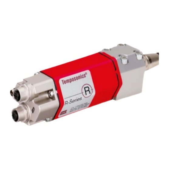
Summary of Contents for MTS Sensors Temposonics Powerlink V2 R Series
- Page 1 Temposonics ® Magnetostrictive Linear Position Sensors R-Series Powerlink V2 Operation Manual...
-
Page 2: Table Of Contents
Temposonics R-Series Powerlink V2 ® Operation Manual Table of contents 1. Introduction ..............................3 1.1 Purpose and use of this manual ................................3 1.2 Used symbols and warnings ..................................3 2. Safety instructions ............................. 3 2.1 Intended use ......................................3 2.2 Forseeable misuse ..................................... -
Page 3: Introduction
The sensor might be damaged. 1 and only in conjunction with the third-party devices and components recommended or approved by MTS Sensors. As a prerequsite of proper and safe operation the product requires correct transport, storage, mounting and commissioning and must be operat ed with utmost care. -
Page 4: Installation, Commissioning And Operation
7. Before applying power, ensure that nobody’s safety is jeopardized by starting machines. 2.4 Safety instructions for use in explosion-hazardous areas The sensor is not suitable for operation in explosion-hazardous areas. 2/ See also applicable MTS Sensors terms of sales and delivery on: www.mtssensors.com I 4 I... -
Page 5: Identification
Temposonics R-Series Powerlink V2 ® Operation Manual 3. Identification 3.1 Order code of Temposonics ® optional a Sensor model Optional: P Profile g Magnet number for multi-position measurement 2 2 magnets b Design 3 3 magnets G Magnet slider, joint on top, backslash free (part no. 253 421) 4 4 magnets M U-magnet, OD33 (part no. -
Page 6: Order Code Of Temposonics ® Rh
Temposonics R-Series Powerlink V2 ® Operation Manual 3.2 Order code of Temposonics ® optional a Sensor model d Connection type 6 2 × M12 female connectors (4 pin), H Rod 1 × M8 male connector (4 pin) b Design e Operating voltage B Base unit 1 +24 VDC (−15 / +20 %) D Threaded flange M18×1.5-6g (bushing on rod end) -
Page 7: Order Code Of Temposonics ® Rd4
Temposonics R-Series Powerlink V2 ® Operation Manual 3.3 Order code of Temposonics ® optional a Sensor model d Stroke length X M Flange »C«, »D«, »G«, »M«, »T«: 4 Detached sensor electronics 0025…5080 mm Flange »S«: 0025…2540 mm b Design Standard stroke length (mm)* Ordering steps C Threaded flange M18×1.5-6g, A/F 46... -
Page 8: Order Code Of Temposonics ® Rf
Temposonics R-Series Powerlink V2 ® Operation Manual 3.4 Order code of Temposonics ® optional a Sensor model F Flexible sensor rod b Design C Base unit M Threaded flange M18×1.5-6g S Threaded flange ¾"-16 UNF-3A c Stroke length (Longer strokes are available. Contact applications engineering for details.) X M 00150…10060 mm Standard stroke length (mm)* Ordering steps... -
Page 9: Nameplate
• The sensor rod or profile protects the inner sensor element. Principle of operation and system construction • The sensor electronics housing, a rugged aluminum construction, The absolute, linear position sensors provided by MTS Sensors contains the complete electronic interface with active signal rely on the company’s proprietary Temposonics magnetostrictive conditioning. -
Page 10: Styles And Installation Of Temposonics ® Rp
Temposonics R-Series Powerlink V2 ® Operation Manual 4.2 Styles and installation of Temposonics ® Sensor electronics housing Null zone Stroke length Dead zone 25…5080 66 / 71* (5.07) (1.1) (1…200) (2.6 / 2.8*) (1.93) M5 or #10 screw Ø 5.5 (0.21) 35.6 (1.4) - Page 11 Temposonics R-Series Powerlink V2 ® Operation Manual 4.3 Styles and installation of Temposonics ® RH-H / -M / -S / -V Sensor electronics housing Null zone Stroke length Dead zone 25…7620 63.5 / 66* (5.24) (2.01) (1…300) (2.5 / 2.6* ) (2.09) (0.71) (0.4)
- Page 12 Temposonics R-Series Powerlink V2 ® Operation Manual R-Series RH-J Null zone Stroke length Dead zone A/F 46 25…7620 73.6 (2.01) (1…300) (2.9) Flange: »J« (0.18) M22×1.5-6g R-Series RH-B Sensor electronics housing Null zone Stroke length Dead zone 25…7620 52 / 54 / 57** (1.93) (4.84 ) (2.4)
- Page 13 Temposonics R-Series Powerlink V2 ® Operation Manual In the case of threaded flange M18×1.5-6g or M22×1.5-6g, provide a screw hole based on ISO 6149-1 (Fig. 11). See ISO 6149-1 for further information. Sealing via O-ring in the flange undercut Fig. 10: Possibilities of sealing •...
-
Page 14: Styles And Installation Of Temposonics ® Rd4
Temposonics R-Series Powerlink V2 ® Operation Manual 4.4 Styles and installation of Temposonics ® Sensor electronics housing with bottom cable entry 24.7 26.5 (0.3) (0.97) (1.04) Sensor electronics housing (0.98) Ø 6.2 Ø 19 (Ø 0.24) (Ø 0.75) Mounting block Sensor electronics housing (1.61) (1.77) - Page 15 Temposonics R-Series Powerlink V2 ® Operation Manual Threaded flange »C« & »D« (for bottom or side entry) PUR-cable: Null zone Stroke length Dead zone Ø 6 (Ø 0.24) 25…5080 63.5 / 66* Bend radius: (1.36) (2.01) (1…200) (2.5 / 2.6) >...
-
Page 16: Installation Of Rd4 With Threaded Flange
Temposonics R-Series Powerlink V2 ® Operation Manual NOTICE Hydraulics sealing There are the following ways to seal the flange contact Note for installation respectively surface (Fig. 16): for replacement For threaded flange »C« / »D«: The serial numbers (S/N:) of cable and sensor electronics housing 1. -
Page 17: Installation Of Rd4 With Pressure Fit Flange
Temposonics R-Series Powerlink V2 ® Operation Manual 4.4.2 Installation of RD4 with pressure fit flange Sensor electronics with bottom cable entry Connect the rod via the connector to the sensor electronics. Mount the Cylinder mounting sensor electronics so that you can lead the cables below the bottom of Install the rod using the pressure fit flange. - Page 18 Temposonics R-Series Powerlink V2 ® Operation Manual Mounting of sensor electronics housing Mount the sensor electronics housing with 4 M6×45 (ISO 4762) screws via the mounting block. Note the fastening torque of 6 Nm. 4 M6×45 (ISO 4762) screws Fastening torque: 6 Nm Mounting block Fig.
-
Page 19: Styles And Installation Of Temposonics ® Rf
Temposonics R-Series Powerlink V2 ® Operation Manual 4.5 Styles and installation of Temposonics ® RF-C Total length Sensor electronics housing Null zone Stroke length Dead zone 150…10060 see table (4.84) (2.4) (6…396) (0.28) 11.5 (0.45) Not flexible (0.71) (4.21) Stroke length Tolerance of total length Dead zone Up to 7620 mm (300.00 in.) - Page 20 Temposonics R-Series Powerlink V2 ® Operation Manual NOTICE Socket head screw M4×90 Smaller radiuses cause damage to the flexible sensor rod. 500 (20) recommended Magnet ≥ 300 (≥ 11.81) Customized support tube required, e.g. Ø 12.7 × 1.65 (0.4) (Ø 0.5 × 0.65), Fastening torque of socket head screw M4×90: 2 Nm inside Ø...
- Page 21 Temposonics R-Series Powerlink V2 ® Operation Manual Hydraulics sealing when using a RF sensor in a pressure rod Notice for metric threaded flanges HD / HL / HP Thread Z° ×P) There are two ways to seal the flange contact surface (Fig. 29): +0.1 +0.4 ±1°...
-
Page 22: Magnet Installation
Temposonics R-Series Powerlink V2 ® Operation Manual Concentric mounting 4.6 Magnet installation of block magnet Magnet Typical sensors Benefits Ring magnets Rod models • Rotationally symmetrical Air gap: 3 ±2 (RH, RD4, RF) magnetic field 8 ±2 (0.12 ±0.08) (0.31 ±0.08) Sensor element U-magnets Profile &... - Page 23 Temposonics R-Series Powerlink V2 ® Operation Manual Start- and end positions of the position magnets Consider the start and end positions of the position magnets during usable, the position magnet must be mechanically mounted as the installation. To ensure that the entire stroke length is electrically follows.
- Page 24 Temposonics R-Series Powerlink V2 ® Operation Manual Multi-position measurement R-Series RF-M / -S with ring magnet & U-magnet The minimum distance between the magnets is 75 mm (3 in.). Sensor electronics housing Reference edge of mounting Profile models with U-magnets Start position End position 51 (2.01)
-
Page 25: Replacement Of Sensor
NOTICE • If necessary, the sensor electronics of sensor model RD4 can be 1. Loosen the screws replaced. Contact MTS Sensors for further information. • Secure the base unit screws, e.g. using Loctite 243, before re-installing. 2 × socket head screw M4×2.5... -
Page 26: Electrical Connections
Temposonics R-Series Powerlink V2 ® Operation Manual 4.8 Electrical connections Connector wiring Connect the sensor directly to the control system, indicator or Placement of installation and cabling have decisive influence on other evaluating systems as follows: the sensor‘s electromagnetic compatibility (EMC). Hence correct installation of this active electronic system and the EMC of the entire system must be ensured by using suitable metal connectors, shielded cables and grounding. -
Page 27: Frequently Ordered Accessories
Temposonics R-Series Powerlink V2 ® Operation Manual 4.9 Frequently ordered accessories – Additional options available in our Accessories Guide 551 444 Position magnets Ø 32.8 57 (2.24) Ø 32.8 (Ø 1.29) (1.69) (0.55) Ø 4.3 (Ø 1.29) (0.55) 49 (1.93) (0.79) Ø... - Page 28 Temposonics R-Series Powerlink V2 ® Operation Manual Sealing Accessory for M12 cable connector Cable connectors 52 (2.05) Ø 27 ~ 43 (Ø 1.06) (~ 1.7) (0.24) A/F 17 A/F 13 (0.05) (0.63) Back-up ring for pressure fi t fl ange M12 male connector (4 pin), straight M8 female connector (4 pin), straight Connector end cap...
- Page 29 Temposonics R-Series Powerlink V2 ® Operation Manual Mounting hardware Pressure rods (RF) M5 thread 60 (2.36) 16 (0.63) (0.16) 11.5 Ø 3.2 (Ø 0.13) (0.45) M3 fastening screws (6×) 3.2 (0.13) (0.31) (1.8) T-slot nut Fixing clip Pressure rod with fl ange Pressure rod with fl...
-
Page 30: Operation
LEDs (red / green) in the sensor electronics housing lid provide These instructions describe the configuration of the node ID of a information on the current sensor condition. MTS Sensors Temposonics R-Series Powerlink sensor using the ® MTS Powerlink software (download at www.mtssensors.com). - Page 31 Temposonics R-Series Powerlink V2 ® Operation Manual 6.1.2 Network adapter set-up 3. Disable “Internet Procotol Version 6 (TCP/IPv6)” (Fig. 48). Step 1: Network adapter set-up Step 2: Node ID configuration Step 3: Process data 1. Open the “Control Panel” > “Network and Internet” > “Network Connections”...
- Page 32 2. Click on “Search for Node” to figure out which node ID the connected sensor has (Fig. 52). The default node ID is 32. Fig. 50: Static IP address NOTICE MTS Sensors recommends for the IP settings: Net ID: 192.168.100.XXX Host ID: 1 –...
- Page 33 Temposonics R-Series Powerlink V2 ® Operation Manual 4. The node ID can be changed by “Change Address”. 6.1.4 Process data A window pops up. Fill in the new node address and click “Ok” (Fig. 54). Step 1: Network adapter set-up ...
-
Page 34: Introduction Of "Automation Studio
Temposonics R-Series Powerlink V2 ® Operation Manual Name Description 6.2 Introduction of “Automation Studio” STATE_SEARCH_FOR_NODE This is the initial state in this project. In this state, PLC tries to read the vendor ID of The following is a description how to set the node ID of a Temposonic ®... - Page 35 Temposonics R-Series Powerlink V2 ® Operation Manual 6.2.3 Used variables 6.2.4 Program executed by PLC once after start-up (SdoAccessInit.c) The following local variables are used to change the node ID (Fig. 61). This program initializes the state of the implemented state machine as well as the node ID variable.
- Page 36 Temposonics R-Series Powerlink V2 ® Operation Manual Source Code “SdoAccessCyclic.c” /******************************************************************** * COPYRIGHT -- ******************************************************************** * Program: SdoAccess * File: SdoAccessCyclic.c * Author: SSchumacher * Created: November 18, 2014 ******************************************************************** * Implementation of program SdoAccess ********************************************************************/ #include <bur/plctypes.h> #ifdef _DEFAULT_INCLUDES #include <AsDefault.h>...
- Page 37 Temposonics R-Series Powerlink V2 ® Operation Manual 6.2.6 Variable watch after successful execution of the implemented state machine As shown in the variable watch, a MTS controlled node has been found at node ID 32 (default node ID when sensors are shipped). The node ID has been successfully set to 1.
-
Page 38: Integration In Automation Studio
Temposonics R-Series Powerlink V2 ® Operation Manual 7. Integration in Automation Studio Adding Temposonics position sensor to a network ® 7.1 Programming and configuration In the right of the main view is the “Toolbox – Hardware Catalog” (Fig. 66). Choose the sensor in the “Toolbox – Hardware Catalog” NOTICE and move the sensor via drag and drop in the physical view where the sensor should be integrated in the network (Fig. - Page 39 However, this is only the case if the configuration of the “Configuration”. The Powerlink parameters are the following: MTS Sensors R-Series Powerlink sensor has been changed, i.e., if the configuration differs from the values in the project tool. Name...
-
Page 40: Communication Segement
Temposonics R-Series Powerlink V2 ® Operation Manual 7.2 Communication Segement Index Subindex Name Object type PDO mapping Attribute Data type Description Indicates the number of magnets with which the sensor 2000 Number of magnets Variable Integer32 is operated (maximum 4 magnets) Measuring direction forward: Head to rod end 2001 Measuring direction... - Page 41 Temposonics R-Series Powerlink V2 ® Operation Manual Index Subindex Name Object type PDO mapping Attribute Data type Description Cam state register Array The parameter “Cam state register” defines the status 6300 bit of the cam in a cam channel. Number of available channels Variable Unsigned8 The status bit set to 1 defines “cam active”.
- Page 42 Temposonics R-Series Powerlink V2 ® Operation Manual Index Subindex Name Object type PDO mapping Attribute Data type Description Cam 1 high limit Array This object determines the higher limit of position 6320 for cam 1 Number of available channels Variable Unsigned8 Cam 1 high limit channel 1 Variable...
-
Page 43: Set The Losssoc Threshold For A R-Series Powerlink Sensor
Temposonics R-Series Powerlink V2 ® Operation Manual Index Subindex Name Object type PDO mapping Attribute Data type Description Work area low limit Array This object contains the position value, at which bit 2 of 6401 the according p406_work_area_state_channel in object Number of available work areas Variable Unsigned8... -
Page 44: Used Variables
Temposonics R-Series Powerlink V2 ® Operation Manual 8.3 Used variables 8.4 Program executed by PLC once after start-up The following local variables are used to read and write values This program just initializes the state of the implemented state from / to the SDO objects (Fig. 74). machine (source code below). -
Page 45: Program Executed By Plc Cyclically
Temposonics R-Series Powerlink V2 ® Operation Manual 8.5 Program executed by PLC cyclically This program implements the state machine and accesses the LossSoC threshold of R-Series Powerlink (source code below). Source code “SdoAccessCyclic.c” /******************************************************************** * COPYRIGHT -- ******************************************************************** * Program: SdoAccess * File: SdoAccessCyclic.c * Author: SSchumacher * Created: November 18, 2014... -
Page 46: Variable Watch After Successful Execution Of The Implemented State Machine
The conditions of transport and storage of the sensor match the operating conditions mentioned in this document. 9.3 Repair Repairs of the sensor may be performed only by MTS Sensors or a repair facility explicitly authorized by MTS Sensors. 10. Removal from service / dismantling The product contains electronic components and must be disposed of in accordance with the local regulations. -
Page 47: Technical Data
Temposonics R-Series Powerlink V2 ® Operation Manual 11. Technical data 11.1 Technical data of Temposonics ® Output Interface Ethernet POWERLINK Data protocol POWERLINK V2 according to IEEE 802.3 Measured value Position, velocity / option: multi-position measurement (2…4 positions) Measurement parameters Resolution 1 μm, 2 μm, 5 μm, 10 μm, 50 μm or 100 μm (selectable) Cycle time... - Page 48 Temposonics R-Series Powerlink V2 ® Operation Manual 11.2 Technical data of Temposonics ® Output Interface Ethernet POWERLINK Data protocol POWERLINK V2 according to IEEE 802.3 Measured value Position, velocity / option: multi-position measurement (2…4 positions) Measurement parameters Resolution 1 μm, 2 μm, 5 μm, 10 μm, 50 μm or 100 μm (selectable) Cycle time 1.0 ms up to 2400 mm stroke length, 2.0 ms up to 4800 mm stroke length,...
- Page 49 Temposonics R-Series Powerlink V2 ® Operation Manual 11.3 Technical data of Temposonics ® Output Interface Ethernet POWERLINK Data protocol POWERLINK V2 according to IEEE 802.3 Measured value Position, velocity / option: multi-position measurement (2…4 positions) Measurement parameters Resolution 1 μm, 2 μm, 5 μm, 10 μm, 50 μm or 100 μm (selectable) Cycle time 1.0 ms up to 2400 mm stroke length, 2.0 ms up to 4800 mm stroke length,...
- Page 50 Temposonics R-Series Powerlink V2 ® Operation Manual 11.4 Technical data of Temposonics ® Output Interface Ethernet POWERLINK Data protocol POWERLINK V2 according to IEEE 802.3 Measured value Position, velocity / option: multi-position measurement (2…4 positions) Measurement parameters Resolution 1 μm, 2 μm, 5 μm, 10 μm, 50 μm or 100 μm (selectable) Cycle time 1.0 ms up to 2400 mm stroke length, 2.0 ms up to 4800 mm stroke length,...
-
Page 51: Appendix
Do not specify chemical formulas. In the event of suspected penetration of substances into the sensor, Please include safety data sheets of the substances, if applicable. consult MTS Sensors to determine measures to be taken before shipment. Short description of malfunction:... - Page 52 MTS, Temposonics and Level Plus are registered trademarks of MTS Systems Corporation in the United States; MTS SENSORS and the MTS SENSORS logo are trademarks of MTS Systems Corporation within the United States. These trademarks may be protected in other countries. All other trademarks are the property of their respective owners. Copyright © 2018 MTS Systems Corporation. No license of any intellectual property rights is granted.
Need help?
Do you have a question about the Temposonics Powerlink V2 R Series and is the answer not in the manual?
Questions and answers