MTS Sensors Temposonics R Series Datasheet
Magnetostrictive, absolute, non-contact linear-position sensors, synchronous serial interface ssi output
Hide thumbs
Also See for Temposonics R Series:
- Operation manual (42 pages) ,
- Datasheet (15 pages) ,
- Datasheet (7 pages)
Table of Contents
Advertisement
Quick Links
Temposonics
Magnetostrictive, Absolute, Non-contact
R-Series Models RP and RH
Synchronous Serial Interface (SSI) Output
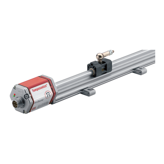
Model RP Profile-style position sensor
FEATURES
„ Linear, Absolute Measurement
„ LEDs For Sensor Diagnostics
„ Non-Contact Sensing Technology
„ Linearity Deviation Less Than 0.01%
„ Repeatability Within 0.001%
„ Direct 24/25/26 Bit SSI Output, Gray/Binary Formats
„ Synchronous Measurement for Accurate Velocity/Acceleration
Calculations
BENEFITS
„ Superior Accuracy; Resolution Down to 0.5 Micron
„ Rugged Industrial Sensor
„ High-Speed Update Options
„ Linearity Correction Options
„ Velocity Output Option
„ Optional Differential Measurement Between Two Magnets
APPLICATIONS
„ Continuous Operation In Harsh Industrial Conditions
„ High Pressure Conditions
„ For Fast, Precision Motion Control
TYPICAL INDUSTRIES
„ Factory Automation
„ Fluid Power
„ Plastic Injection and Blow Molding
„ Material Handling and Packaging
„ Woodworking, Metalworking and Machine Tools
Linear-Position Sensors
Data Sheet
®
Model RH Rod-style position sensor
Time-based Magnetostrictive position sensing principle
Movable position magnet
Magnetic field encompasses
entire waveguide - generated
by the interrogation pulse
Interrogation
Return wire
Waveguide
Strain-Pulse detector
Bias magnet
Benefits of Magnetostriction
Temposonics
linear-position
magnetostrictive position sensing principle developed by MTS.
Within the sensing element, a sonic-strain pulse is induced in a
specially designed magnetostrictive waveguide by the momentary
interaction of two magnetic fields. One field comes from a moveable
permanent magnet that passes along the outside of the sensor. The
other field comes from an "interrogation" current pulse applied along
the waveguide. The resulting strain pulse travels at sonic speed along
the waveguide and is detected at the head of the sensing element.
The position of the magnet is determined with high precision and
speed by accurately measuring the elapsed time between the applica-
tion of the interrogation pulse and the arrival of the resulting strain
pulse with a high-speed counter. The elapsed time measurement is
directly proportional to the position of the permanent magnet and is
an absolute value. Therefore, the sensor's output signal corresponds
to absolute position, instead of incremental, and never requires
recalibration or re-homing after a power loss. Absolute, non-contact
sensing eliminates wear, and guarantees the best durability and
output repeatability.
All specifications are subject to change. Contact MTS for specifications and
engineering drawings that are critical to your application. Drawings contained
in this document are for reference only. Go to http://www.mtssensors.com for
the latest support documentation and related media.
SENS
RS
O
Document Part Number
550989 Revision E
Magnetic field from
position magnet
Interaction of magnetic
fields causes waveguide to
generate a strain pulse
sensors
use
the
time-based
®
Advertisement
Table of Contents

Related Manuals for MTS Sensors Temposonics R Series


Summary of Contents for MTS Sensors Temposonics R Series
- Page 1 Temposonics ® ® Magnetostrictive, Absolute, Non-contact SENS Linear-Position Sensors R-Series Models RP and RH Document Part Number Synchronous Serial Interface (SSI) Output 550989 Revision E Data Sheet Model RP Profile-style position sensor Model RH Rod-style position sensor Time-based Magnetostrictive position sensing principle FEATURES Movable position magnet „...
-
Page 2: Product Overview
1), or Class 2 rating according to the National Electrical Code (USA) / Canadian Electrical Code. ** The IP rating is not part of the UL Recognition. R-Series Models RP and RH Temposonics Linear-Position Sensors - SSI Output ® Product Data Sheet, Part No.: 550989 Revision E (EN) 05/2014 MTS Sensors... -
Page 3: Synchronous Serial Interface (Ssi)
Sensor measurement cycle Measurement starts Data available Data delivered Figure 4. Asynchronous measuring mode, controller loop timing R-Series Models RP and RH Temposonics Linear-Position Sensors - SSI Output ® MTS Sensors Product Data Sheet, Part No.: 550989 E (EN) 05/2014... - Page 4 Many motion control applications require velocity and/or acceleration be calculated, and therefore, must rely on position data having minimal delay, and minimal timing variability. With the Synchronous Measuring Mode, MTS Sensors has developed a proprietary algorithm to not only guarantee true measurement synchronization but at the same time minimize any propagation delay relative to the controller loop rate.
-
Page 5: Enhanced Monitoring And Diagnostics
(see ‘Figure 8’). The setup software allows the following set of parameters to be field programmed. R-Series Models RP and RH Temposonics Linear-Position Sensors - SSI Output ® MTS Sensors Product Data Sheet, Part No.: 550989 E (EN) 05/2014... -
Page 6: Model Rp Profile-Style Sensor Dimension References
For Model RP profile-style sensor Ball-jointed arm (M5 thread) 9 mm 40 mm (0.35 in.) (1.58 in.) R-Series Models RP and RH Temposonics Linear-Position Sensors - SSI Output ® Product Data Sheet, Part No.: 550989 Revision E (EN) 05/2014 MTS Sensors... - Page 7 (optional, ordered separately) 5 mm (0.20 in.) M5 Threaded stud and nut T-Slot nut, M5 thread Detail R-Series Models RP and RH Temposonics Linear-Position Sensors - SSI Output ® MTS Sensors Product Data Sheet, Part No.: 550989 E (EN) 05/2014...
- Page 8 46 mm 53 mm Table 2. Model RH Rod-style sensor housing style and flange type references R-Series Models RP and RH Temposonics Linear-Position Sensors - SSI Output ® Product Data Sheet, Part No.: 550989 Revision E (EN) 05/2014 MTS Sensors...
- Page 9 (This float is used with the Model RH 3.4 mm (0.13 in.) rod-style sensors for hydraulic fluid or fresh water applications only) R-Series Models RP and RH Temposonics Linear-Position Sensors - SSI Output ® MTS Sensors Product Data Sheet, Part No.: 550989 E (EN) 05/2014...
-
Page 10: Model Rh Rod-Style Sensor Mounting
(2) M4 thread 2.5 mm hex socket head screws Figure 14. Fluid cylinder installation R-Series Models RP and RH Temposonics Linear-Position Sensors - SSI Output ® Product Data Sheet, Part No.: 550989 Revision E (EN) 05/2014 MTS Sensors... -
Page 11: Connections And Wiring
7-Pin DIN (D70) 18 mm Mates with standard male (M16) (0.7 in.) dia. integral connector 54 mm (2.1 in.) R-Series Models RP and RH Temposonics Linear-Position Sensors - SSI Output ® MTS Sensors Product Data Sheet, Part No.: 550989 E (EN) 05/2014... - Page 12 = Cable length (maximum cable length is dependent on baud rate). 6 - 7 CABLE TERMINATION = Pigtail cable without connector R-Series Models RP and RH Temposonics Linear-Position Sensors - SSI Output ® Product Data Sheet, Part No.: 550989 Revision E (EN) 05/2014 MTS Sensors...
- Page 13 OPTIONAL ADVANCED OUTPUTS (18- 22) + the 3 digit Output code defined (Continue to the next page) R-Series Models RP and RH Temposonics Linear-Position Sensors - SSI Output ® MTS Sensors Product Data Sheet, Part No.: 550989 E (EN) 05/2014...
-
Page 14: Ordering Information
= Additional alarm bit + even parity bit = Additional alarm bit + even parity bit + LCO R-Series Models RP and RH Temposonics ® Linear-Position Sensors - SSI Output Product Data Sheet, Part No.: 550989 Revision E (EN) 05/2014 MTS Sensors... - Page 15 Fax + 39 030 982 3359 Fax + 49 2351 56491 info.it@mtssensors.com info.de@mtssensors.com www.mtssensor.com www.mtssensor.de JAPAN CHINA MTS Sensors Technology Corp. MTS Sensors 737 Aihara-machi, Room 504, Huajing Commercial Center, Machida-shi, No. 188, North Qinzhou Road Tokyo 194-0211, Japan 200233 Shanghai, China Tel.
Need help?
Do you have a question about the Temposonics R Series and is the answer not in the manual?
Questions and answers