MTS Sensors Temposonics R Series Operation Manual
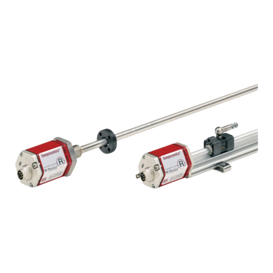
Absolute, non-contact position sensors
Hide thumbs
Also See for Temposonics R Series:
- Operation manual (42 pages) ,
- Datasheet (16 pages) ,
- Datasheet (13 pages)

Related Manuals for MTS Sensors Temposonics R Series


Summary of Contents for MTS Sensors Temposonics R Series
- Page 1 Temposonics ® Absolute, Non-Contact Position Sensors OPERATION MANUAL R-Serie Analog...
-
Page 2: Table Of Contents
1 and item 2 and only in conjunction with the third-party devices 8. Technical data ................20 and components recommended or approved by MTS Sensors. As a 8.1 Input ..................20 prerequsite of proper and safe operation, the product requires correct 8.2 Output ................. -
Page 3: Installation, Commissioning And Operation
Operation Manual RP & RH Analog 2.2 Installation, commissioning and operation If danger of injury to persons or of damage to operating equipment is caused by sensor failure or malfunction, additional safety measures such as plausibility checks, limit switches, EMERGENCY STOP sys- tems, protective devices etc. - Page 4 Operation Manual RP & RH Analog Ordering code (3 / 7 digits) a Specification e Output - 1 Output with 1 magnet (Pos. magnet 1) P Profile 1 0…10 VDC H Rod 1 10…0 VDC 1 −10…+10 VDC b Profile - Temposonics 1 +10…−10 VDC ®...
-
Page 5: Nameplate (Example)
Operation Manual RP & RH Analog 3.2 Nameplate (example) Measuring range (e.g. 850 mm) Connection type Sensor model Part No. Output version RP-S-0850M-D34-1-V01 Output 0 - 10 V FNr. 1413 3950 Production No. Year Week 3.3 Approvals The sensor conforms to the EU directives and is provided with CE and GOST marking. -
Page 6: Styles And Installation
Operation Manual RP & RH Analog 4.2 Styles and installation Temposonics RP profile style ® Purpose: e.g. mounting on machines The profile-style sensor can be operated with various position magnets: - Profile-guided magnet carriages are connected to the mobile - A free position magnet on the mobile machine part travels along the machine part via a ball coupling to compensate alignment errors. -
Page 7: Electrical Connection
Operation Manual RP & RH Analog Temposonics RH rod style ® Purpose: e.g. installation in hydraulic cylinders The pressure-resistant stainless steel rod is installed in the fluid power Advantage... system in the cylinder and externally, if space conditions are limited. For servicing the complete basic sensor can be easily replaced Position measurement is contactless via ring or U-magnets. - Page 8 Operation Manual RP & RH Analog Active measuring range Installation of a profile-style sensor The technical data of each sensor is checked as well as documented The position sensor can be installed in any position. Normally, the and the active stroke length (useful electrical stroke) with its start sensor is firmly installed and the position magnet is fastened to the and end position is adjusted during final inspection and testing (see mobile machine part.
- Page 9 5 mm Operation Manual RP & RH Analog Fig. 7 T-slot nuts M5 Rod with inner sensor element immersed in the cylinder Mounting the U-magnet Pressure-resistant The U-magnet is removable and can be used for profile- and rod-style sensor housing sensors.
- Page 10 Operation Manual RP & RH Analog Hydraulics sealing Connection types We recommend sealing the flange contact surface using an O-ring The sensor must be connected directly with the control system (e.g. 22.4 × 2.65) in a cylinder bottom groove. However, sealing via accouding to wiring diagram: a 15.3 ×...
-
Page 11: Accessories
Operation Manual RP & RH Analog 4.4 Accessories Position magnets for sensor profile 20,7 20.7 Max. Luftspalt Max. gap 3 mm (±1) 3 mm (±1) Magnetschlitten V U-magnet OD33 Magnet slider S Ø 32.8 Ø 4.3 Ø 4.3 on Ø 23.8 bolt circle Ø... -
Page 12: Operation
Operation Manual RP & RH Analog MTS Servicetools Analog hand programmer – R-Series Programming kit – R-Series Analog cabinet programmer – R-Series (for sensors with 1 magnet) (for sensors with 1 or 2 magnets) Part no. 253 408 Part no. 253 124 Part no. -
Page 13: Programming And Configuration
– without opening ® sensor housing – to changing measuring tasks via connecting wires. Therefore the user can use several MTS Sensors Servicetools which can be chosen from the accessories. Handheld-Programmer R-Analog, 1 Magnet sensor Part no. - Page 14 Operation Manual RP & RH Analog Cabinet-Programmer R-Analog, Part no. 253 408 Cabinet-Programmer R-Analog, connected between sensor and control unit is provided for setup of measuring range by moving the Program /Run 24 VDC Program /Run 24 VDC magnet on desired Null/Span positions (minimum distance between setpoints: 25 mm) and pushing the corresponding 0 % respectively Start Programming mode...
- Page 15 Parameters of 1 or 2 magnets sensors – Green LED 24 VDC shows normal function can be changed within the active stroke via Windows PC and analog configurator by MTS Sensors. Activate Programming mode: – Sliding switch on PROGRAMM Depending on the sensor design, tool allows menu-driven change of: –...
- Page 16 Operation Manual RP & RH Analog Connect programmer NOTICE – Connect programmer with the sensor via the corresponding cable. – Connect the programmer via USB port with the PC. Do not make connections under voltage! – Connect the power supply via jack on the side. The external contact of the connector is 0 V (ground).
- Page 17 Operation Manual RP & RH Analog (11) (12) (10) Fig. 27: Example of windows surface Fig. 29: Example of tab controls Status indicates that the sensor is connected successfully. Thereby, field Output Minimum indicates the current or voltage Frame Sensor Information contains the invariable sensor parame- value which should be output at the starting point of the selected ters, which are read in automatically when connecting the sensor.
- Page 18 Operation Manual RP & RH Analog NOTICE Setting examples for hand-held programming device or installation programmer Regardless of the direction of measurement, the set points The sensor measurement range can be positioned with the tools SP1 always the electronics housing and SP2 are always described forward any time.
-
Page 19: Maintenance And Troubleshooting
Operation Manual RP & RH Analog 6. Maintenance and troubleshooting 6.4 List of spare parts Omitted 6.1 Error conditions, troubleshooting See chapter 5 “Operation”, fig. 18. 7. Removal from service 6.2 Maintenance The sensor is maintenance-free. 7.1 Disposal The product contains electronic components and must be disposed 6.3 Repair of in accordance with the local regulations. -
Page 20: Technical Data
Operation Manual RP & RH Analog 8. Technical data 8.1 Input Measured value Position / velocity / dual magnet position measurements Stroke length Profile: 25…5000 mm / rod: 25…7600 mm 8.2 Output 1. Voltage 0…10 / 10…0 / −10…+10 / +10…−10 VDC (min. load controller: > 5 kOhm) 2. -
Page 21: Annex
9. Annex Safety Declaration Dear Customer, If you return one or several for checking or repair, we need you to sign a safety declaration. The purpose of this declaration is to ensure that the returned items do not contain residues of harmful substances and / or that any danger to persons when handling these items is excluded. MTS order number: ___________________________________ Sensor type(s): _________________________________________... -
Page 22: Notes
Operation Manual RP & RH Analog Notes... - Page 23 MTS, Temposonics and Level Plus are registered trademarks of MTS Systems Corporation in the United States; MTS SENSORS and the MTS SENSORS logo are trademarks of MTS Systems Corporation within the United States. These trademarks may be protected in other countries. All other trademarks are the property of their respective owners. Copyright © 2018 MTS Systems Corporation. No license of any intellectual property rights is granted.
Need help?
Do you have a question about the Temposonics R Series and is the answer not in the manual?
Questions and answers