Table of Contents
Advertisement
Advertisement
Table of Contents

Related Manuals for Pyronix Castle EURO 46S


Summary of Contents for Pyronix Castle EURO 46S
- Page 1 EURO 46 Installation Manual EN50131-3:2009 EN50131-1:2006+A1:2009 PD6662:2010 EURO 46S: Security Grade 2 Environmental Class II EURO 46L: Security Grade 3 Environmental Class II Software Version >9.1 Installation Reference For the EURO 46S and EURO 46L control panels RINS1533-3 Page: 1...
-
Page 2: Table Of Contents
EURO 46 Installation Manual C o n t e n t s P a g e Contents Page ............................. 2 1. System Overview ............................. 3 1.1 System Overview..........................3 1.2 The Devices ............................4 1.3 EURO Input Mapping Overview: ......................6 1.4 Output Mapping Overview ........................ -
Page 3: System Overview
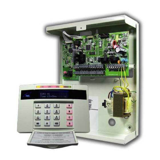
EURO 46 Installation Manual 1 . S y s t e m O v e r v i e w The EURO 46 is wired control panel that can have a maximum of 46 inputs. The EURO 46 can be purchased in a EURO-46S (Small Metal Casing: Grade 2), or a EURO 46L (Small Metal Casing: Grade 3). -
Page 4: The Devices
EURO 46 Installation Manual 1.2 The Devices 1.2.1 The EURO 46 Bus Diagram All EURO peripherals; LCD keypads, readers, expanders etc. are connected via the D1-, D2+, D3 and D4 terminals. This is an example of what a typical EURO 46 bus may look like. - Page 5 EURO 46 Installation Manual 1.2.2 RS-485 Wiring Wiring Format Bus range Cable type Screened Cable Daisy Chain Range Star Range 4 core alarm cable No limit. 300m Use when bus A 470ohm resistor located near should be used to 6 core alarm cable 230VAC mains terminate the bus.
-
Page 6: Euro Input Mapping Overview
EURO 46 Installation Manual 1.3 EURO Input Mapping Overview: 1.3.1 EURO 46 Input Mapping Table: DEVICES Address Input Numbers EURO 46 PCB 9-16 17-24 EURO-ZEM8 / EURO-ZEM8+/ EURO-ZEM8+PSU / EURO-ZEM32-WE 25-32 33-40 EURO-LCD 41-42 43-44 EURO-LCD / EURO-PROXI* 45-46 Total NOTE 1: 1 x EURO-ZEM32-WE can be connected to the EURO 46. -
Page 7: Installation
EURO 46 Installation Manual 2 . I n s t a l l a t i o n 1. Unscrew and remove the cover of the EURO 46 (Figure 1). 2. Install the supplied stand offs if needed before you mount the metal case to the wall (Figure 3). Figure 1. -
Page 8: The Printed Circuit Board
EURO 46 Installation Manual 3 . T h e P r i n t e d C i r c u i t B o a r d 1] Output 1 Relay output. See page: 16. 2] External sounder connections and Speaker connection Connects an external sounder (page: 17) and a 16ohm speaker (page:... -
Page 9: Technical Specification
EURO 46 Installation Manual 3.1 Technical Specification Programmable Outputs Power Rating Normal State Active State PGM 1 Relay, 3A, max 30V Changeover NC & NO Changeover NC & NO Speaker 16 ohms No tones Repeat RKP tones & internal sounder Strobe Output 500mA Bell Output... - Page 10 EURO 46 Installation Manual EN50131-6:2008 Rated Output In accordance with EN50131-6:2008, the EURO standby times and effective output currents depend on the Security Grade of the system and how 230V mains missing fault is signalled to the Alarm Receiving Centre. Power supplies are rated in accordance with the requirements of EN50131-6, which are related to the maximum battery size that can be accommodated in the housing and vary according to the grade of the system in which they are installed, as per the following table:...
-
Page 11: Important Installation Notes
EURO 46 Installation Manual 3.2 Important Installation Notes Ensure wiring is done to the national wiring regulations in the country where the installation is taking place. In the UK, this is BS 7671 Requirements for electrical installations; IET Wiring Regulations (17th edition). -
Page 12: Power And Battery Connections
EURO 46 Installation Manual 3.4 Power and Battery Connections 3.4.1 The EURO 46 Large (Grade 3) Panel Power Supply Input Nominal Range Mains Supply Voltage AC 230V AC at 50Hz -15% +10% Transformer Rating EURO 46L 45VA 18.5V at 2.5A Panel Power Supply Output Nominal Range... - Page 13 EURO 46 Installation Manual 3.4.2 The EURO 46 Small (Grade 2) Panel Power Supply Input Nominal Range Mains Supply Voltage AC 230V AC at 50Hz -15% +10% Transformer Rating EURO 46S 18VA 18V at 1.0A Panel Power Supply Output Nominal Range Output Voltage 13.7V DC...
-
Page 14: Input Connections
EURO 46 Installation Manual 4 . I n p u t C o n n e c t i o n s Input Resistance 1k / 1k DEOL Range 4k7 / 2k2 DEOL Range 4k7 / 4k7 DEOL Range Normal 0k5 to 1k4 1k4 to 2k9 3k7 to 8k3... -
Page 15: Default Grade 2 Deol (Double End Of Line) Input Wiring
EURO 46 Installation Manual 4.2 Default Grade 2 DEOL (Double End of Line) Input Wiring The above wiring example shows the connections for a Grade 2 KX15DQ PIR detector. 4.3 Grade 3 Mask/Fault Input Wiring The above wiring example shows the connections for a Grade 3 KX15DTAM detector. Page: 15... -
Page 16: Output (Pgm) Connections
EURO 46 Installation Manual 5 . O u t p u t ( P G M ) C o n n e c t i o n s 5.1 Negative Applied Wiring Normal State: NC Active State: 0V Relay Rated at 2A 5.2 XPGM Connections If Inputs 7 and 8 are programmed as ‘unused’, these inputs can be used as 2 further outputs (known as XPGM1 and XPGM2 which can be programmed in the Engineer menu ‘CHANGE OUTPUTS’). -
Page 17: External Sounder Connections
6.1 Grade 3 External Sounder Wiring Pyronix Grade 3 External Sounders: Deltabell Plus Deltabell X Invincibell Plus Invincibell X 6.2 Grade 2 External Sounder Wiring with a Grade 3 Bell Pyronix Grade 3 External Sounders: Deltabell Plus Deltabell X Invincibell Plus Invincibell X Page: 17... -
Page 18: Grade 2 External Sounder Wiring
EURO 46 Installation Manual 6.3 Grade 2 External Sounder Wiring Pyronix Grade 2 External Sounders: Deltabell E Invincibell E Page: 18... -
Page 19: Connecting The Euro Peripherals
EURO 46 Installation Manual 7 . C o n n e c t i n g T h e E U R O P e r i p h e r a l s 7.1 Connecting The LCD Keypad (EURO-LCD) The EURO-LCD keypad is used for programming and user operation. - Page 20 EURO 46 Installation Manual The default address is '00'. Enter the required Address and press Press a to exit. You must now address is from the menu "ASSIGN KEYPADS/READERS". 7.1.3 Addressing the EURO-LCD Keypad (From the Engineer Menu) Enter the engineers menu and scroll to 'ASSIGN KEYPADS/READERS' and press . Please see the Programming Manual for more information.
- Page 21 EURO 46 Installation Manual 7.1.1 Connecting the EURO-LCD Keypad Inputs (Grade 3) The above wiring example shows the connections for a Grade 3 KX15DTAM PIR. 7.1.2 Connecting the Outputs Normal State: 12V Active State: 0V Current: 100mA Page: 21...
-
Page 22: Connecting The Internal Tag Reader (Euro-Proxi)
EURO 46 Installation Manual 7.2 Connecting The Internal Tag Reader (EURO-PROXI) The Internal Tag Reader can have 2 inputs connected. It can be used as a set, unset, entry control or an access control device. NOTE: See the reader installation manual for the LED and button explanations. - Page 23 EURO 46 Installation Manual 7.2.3 Adding the Internal Tag Reader (From the Engineer Menu) Enter the engineers menu and scroll to 'ASSIGN KEYPADS/READERS' and press . Please see the Programming Manual for more information. 7.2.4 Connecting the Internal Tag Reader Inputs The above wiring example shows the connections for a Grade 2 KX15DQ PIR.
-
Page 24: Connecting The External Proximity Reader (Euro-Proxe)
EURO 46 Installation Manual 7.3 Connecting The External Proximity Reader (EURO-PROXE) The External Proximity Reader can be used as either a set unset, entry control or an access control device. NOTE: See the reader installation manual for the LED and button explanations. - Page 25 EURO 46 Installation Manual 7.3.3 Adding the External Tag Reader (From the Engineer Menu) Enter the engineers menu and scroll to 'ASSIGN KEYPADS/READERS' and press . Please see the Programming Manual for more information. 7.3.4 Connecting a Mag Lock and a Request to Exit Button to the External Tag Reader The diagram show the relay mag lock control switching positive and shows a normally open request to exit button, and takes “0V”...
- Page 26 EURO 46 Installation Manual 7.3.6 Using the External Tag Reader for Arming and Entry Control 7.3.7 Using the Request to Exit button 7.3.8 Using the External Tag Reader Disarming Page: 26...
-
Page 27: Connecting The Zone Expander Module (Euro-Zem8)
EURO 46 Installation Manual 7.4 Connecting The Zone Expander Module (EURO-ZEM8) 7.4.1 The EURO-ZEM8 Expander EURO-ZEM8 The EURO-ZEM8 is an input expander that supports 8 inputs. It also supports NC (normally closed), DEOL input and 3 Resistor (Grade 3) configurations. The EURO 46 will support up to 4 x Zone Expander Modules. - Page 28 EURO 46 Installation Manual 7.4.4 Addressing The EURO-ZEM8 (From The Expander) NOTE: The addressing is done by adding the relevant numbers on the dip switches: For example: Dip switch 1 and 2 are only ON = Address 3. Dip switch 1 and 16 are only ON = Address 17 etc. 7.4.5 Adding the EURO-ZEM8 (From the Engineer Menu) Enter the engineers menu and scroll to 'INSTALL ZEM?' and press .
- Page 29 EURO 46 Installation Manual 7.4.7 Wiring Inputs on the EURO-ZEM8 (DEOL: Grade 2) The above wiring example shows the connections for a Grade 2 KX15DQ PIR. 7.4.8 Wiring Inputs on the EURO-ZEM8 (Mask/Fault: Grade 3) The above wiring example shows the connections for a Grade 3 KX15DTAM PIR. Page: 29...
-
Page 30: Connecting The Zone Expander Module With 4 Pgms (Euro-Zem8+)
EURO 46 Installation Manual 7.5 Connecting The Zone Expander Module with 4 PGMs (EURO-ZEM8+) EURO-ZEM8+ The EURO-ZEM8+ is an input expander that supports 8 inputs and 4 PGMs. It also supports NC (normally closed), DEOL input and Mask/Fault (Grade 3) configurations. The EURO 46 will support up to 4 x Zone Expander Module. - Page 31 EURO 46 Installation Manual 7.5.2 EURO-ZEM8+ Input Configuration 7.5.3 Addressing the EURO-ZEM8+ NOTE: The addressing is done by headers that represent the address. For example: If a header is placed on 00, and 9, the address is 9. If a header is placed on 20, and 3, the address is 23 etc. 7.5.4 Adding the EURO-ZEM8+ (From the Engineer Menu) Enter the engineers menu and scroll to 'INSTALL ZEM' and press .
- Page 32 EURO 46 Installation Manual 7.5.5 Wiring Inputs on the EURO-ZEM8+ (Normally Closed) The above wiring example shows the normally closed connection for a KX15DQ PIR. 7.5.6 Wiring Inputs on the EURO-ZEM8+ (DEOL - Grade 2) The above wiring example shows the connections for a Grade 2 KX15DQ PIR. Page: 32...
- Page 33 EURO 46 Installation Manual 7.5.7 Wiring Inputs on the EURO-ZEM8+ (Mask/Fault - Grade 3) The above wiring example shows the connections for a Grade 3 KX15DTAM PIR. 7.5.8 Output Wiring on the EURO-ZEM8+ Normal State: 12V Active State: 0V Max Current: 100mA Page: 33...
-
Page 34: Connecting The Zone Expander Module With Psu (Euro-Zem8+Psu)
EURO 46 Installation Manual 7.6 Connecting The Zone Expander Module with PSU (EURO-ZEM8+PSU) EURO-ZEM8+PSU The EURO-ZEM8+ is an input expander that supports 8 inputs and 4 PGMs and has a built in 2.5 power supply. It also supports NC (normally closed), DEOL input and Mask/Fault (Grade 3) configurations. - Page 35 EURO 46 Installation Manual 7.6.2 EURO-ZEM8+PSU Input Configuration 7.6.3 Addressing the EURO-ZEM8+PSU NOTE: The addressing is done by headers that represent the address. For example: If a header is placed on 00, and 9, the address is 9. If a header is placed on 20, and 3, the address is 23 etc. 7.6.4 Adding the EURO-ZEM8+PSU (From the Engineer Menu) Enter the engineers menu and scroll to 'INSTALL ZEM' and press .
- Page 36 EURO 46 Installation Manual 7.6.5 Wiring Inputs on the EURO-ZEM8+PSU (Normally Closed) The above wiring example shows the normally closed connections for a KX15DQ PIR. 7.6.6 Wiring Inputs on the EURO-ZEM8+PSU (DEOL: Grade 2) The above wiring example shows the connections for a Grade 2 KX15DQ PIR. Page: 36...
- Page 37 EURO 46 Installation Manual 7.6.7 Wiring Inputs on the EURO-ZEM8+PSU (Mask/Fault: Grade 3) The above wiring example shows the connections for a Grade 3 KX15DTAM PIR. 7.6.8 Output Wiring on the EURO-ZEM8+PSU Page: 37...
-
Page 38: Connecting The Enforcer Wireless Zone Expander Module (Euro-Zem32-We)
EURO 46 Installation Manual 7.7 Connecting The Enforcer Wireless Zone Expander Module (EURO-ZEM32-WE) EURO-ZEM32-WE The EURO-ZEM32-WE is a wireless input expander that supports Two Way wireless Enforcer technology. Each expander will allow 32 wireless inputs. The first expander on the bus will allow 32 wireless keyfobs and 2 wireless bells. - Page 39 EURO 46 Installation Manual Addressing Example: Having 32 wireless inputs on the EURO 46 EURO-ZEM32-WE: DEVICE A This expander will learn all 32 wireless keyfobs and 2 wireless bells. Address 0 = 8 wireless inputs (Inputs 9-16) Address 1 = 8 wireless inputs (Inputs 17-24) ...
-
Page 40: Connecting The Output Expander Module (Euro-Oem8R8T)
EURO 46 Installation Manual 7.8 Connecting The Output Expander Module (EURO-OEM8R8T) EURO-OEM8R8T The EURO-OEM8R8T is an output expander that supports 8 way relays and 8 transistor outputs. The EURO 46 will support up to 2 x Output Expander Modules. See page: 4. 7.8.1 EURO-OEM8R8T Technical Specification EURO-OEM8R8T (Output expander with 16 PGMs) Supply Voltage... - Page 41 EURO 46 Installation Manual 7.8.4 EURO-OEM8R8T Output Connections Page: 41...
-
Page 42: Connecting The Output Expander Module With Psu (Euro-Oem16R+Psu)
EURO 46 Installation Manual 7.9 Connecting The Output Expander Module with PSU (EURO-OEM16R+PSU) EURO-OEM16R+PSU The EURO-OEM16R+PSU is an output expander that supports 16 relays and has a built in 2.5A power supply. The EURO 46 will support up to 2 x Output Expander Modules. - Page 43 EURO 46 Installation Manual 7.9.3 Adding The EURO-OEM16R+PSU (From the Engineer Menu) Enter the engineers menu and scroll to 'CHANGE OUTPUTS' and then 'Output Module Outputs' and press . Please see the Programming Manual for more information. 7.9.4 EURO-OEM16R+PSU PGM Connections (Negative and Positive Applied Wiring) Page: 43...
-
Page 44: The Inovonics Radio Expander
EURO 46 Installation Manual 8 . T h e I n o v o n i c s R a d i o E x p a n d e r This radio expander is an 868 inovonics receiver and programming PCB. It will connect to the EURO 46 via the D1, D2, D3, and D4 terminals. -
Page 45: Assigning Radio Detectors
EURO 46 Installation Manual 8.4 Assigning Radio Detectors Press the ‘AZ’ and scroll to the input number you wish to assign a wireless detector to: Press the ‘’RESET’ button on the detector you wish to assign to that particular input. Ensure that the jumper on the detector PCB is placed in the “EU”... -
Page 46: Problem Solving
EURO 46 Installation Manual 8.9 Problem Solving One of the most frequent problems in not being able to assign the detectors to the Radio Expander is that the jumper on the detector PCB has not been put in place on the ‘EU’ pins. This makes sure the transmitter transmits at the correct 868MHz frequency which the input expander uses. -
Page 47: The Pstn Modem
EURO 46 Installation Manual 9 . T h e P S T N M o d e m NOTE: The connector labelled 'FOR FUTURE USE' on board the EURO 46 should not be used. Connecting the PSTN modem in the EURO 46L Connecting the PSTN modem in the EURO 46S On the EURO 46 Large, the Digi-1200 (PSTN) On the EURO 46 Small, the Digi-1200 (PSTN) -
Page 48: Connecting To The Upload/Download Software
The EURO 46 control panel can be programmed by the LCD menu or the UDL InSite Software provided free of charge. It can be downloaded from http://www.pyronix.com/pyronix-downloads.php. The connection between control panel and UDL software can be done in the following ways: 9.1.1 Serial Connection (RS232) -
Page 49: Access Levels
EURO 46 Installation Manual 8. Insert the telephone number in “Telephone Number” field 9. Enter the Engineer code in the “Engineer Code” field 10. Click on “dial” 11. If connection is successful, the modem Icon will become blue. NOTE: If a Site Name is set up on the panel the UDL Site Name must be the same otherwise the connection will not be possible. - Page 50 EURO 46 Installation Manual Page: 50...
- Page 51 EURO 46 Installation Manual Page: 51...
- Page 52 Pyronix Ltd Secure House Braithwell Way Hellaby Rotherham S66 8QY Customer Support line (UK Only): +44(0)845 6434 999 (local rate) or +44(0)1709 535225 Hours: 8:00am - 6:30pm, Monday to Friday Email: customer.support@pyronix.com Website: www.pyronix.com The symbol shown here and on the product, means that the product is...
Need help?
Do you have a question about the Castle EURO 46S and is the answer not in the manual?
Questions and answers