Table of Contents
Advertisement
Advertisement
Table of Contents

Subscribe to Our Youtube Channel
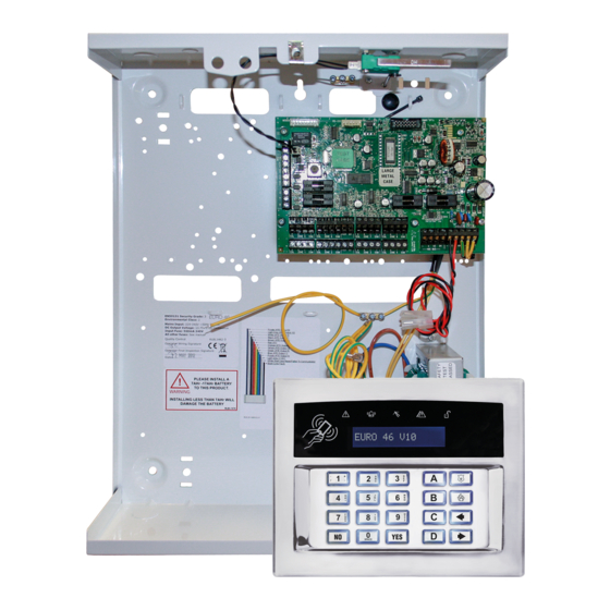
Related Manuals for Pyronix EURO 46 APP


Summary of Contents for Pyronix EURO 46 APP
-
Page 2: Table Of Contents
Keyfobs and now Wireless Arming Stations. 2.1.2 User Automation Outputs The EURO 46 APP Panel includes user automation outputs that provides the option to operate up to 20 devices, such as gates, lights and sprinklers, via the keypad or remotely via a keyfob, thus extending the use of the Panel. -
Page 3: Pyronixcloud And Homecontrol+ App
2.2 PyronixCloud and HomeControl+ App Page: 3... -
Page 4: Writing Texts On The Keypad
3. Writing Texts on the keypad On the Euro 46 APP Panel it is possible to label the following: Inputs – 2 labels: Input Number and Location Area Names Site Name Keypad/Reader – 2 labels: Keypad Number and Location Input and Output expander location descriptions User Names The Control Panel incorporates a predictive text feature (T9 type), such as: enter ‘B’... -
Page 5: Entering The Engineer Menu (Default Engineer Code = 1111)
4.2 Entering The Engineer Menu (Default Engineer Code = 1111) Access to the Engineer menu may be denied if: 1) One or more areas are currently set. 2) The Master User has disabled the function ‘Allow Engineer Menu’ in the Master Manager menu. If this is the case ‘Authorisation required’... -
Page 6: Wireless Device Control
5.3 Wireless Device Control? This function learns or deletes all wireless inputs and bells to the Euro 46 APP Panel, if you have a wireless ZEM installed (EURO-ZEM32-WE). NOTE: The keyfobs are learned and programmed from the Master Manager menu. - Page 7 Delete All Enter Code To delete all wireless bells enter ‘2000’ (this is the Panel Security Code). ‘Please wait’ will be displayed while the Euro 46 APP Panel deletes them. Select Bell to Delete This option deletes only a specific wireless bell that is learnt. Any bells that display ‘learnt’ can be deleted.
- Page 8 This option deletes only a specific Wireless Arming Station that is learnt. Any Arming Stations that display ‘learnt’ can be deleted. ‘Please wait’ will be displayed while the Euro 46 APP Panel deletes the Wireless Arming Station. Return to this process to delete more devices.
-
Page 9: Change Inputs
5.4 Change Inputs? By default, all inputs are set to ‘unused’. Before programming, identify the input type required: These inputs cannot be bypassed. Use of inputs 20 and 23 will make the system unable to comply with EN50131-1 Security Grade 2. Ensure that these inputs are used on an entry/exit route 5.4.1 Choose Input Choose an input to program. - Page 10 This input type is designed specifically for use with systems installed using BS8243 option 6.4.5.This input type is always used in conjunction with an Entry/Exit input. The Entry/Exit input is a door contact on the initial entry door, and the Entry Shock input is a non-latching shock sensor fitted to the door frame in the vicinity of the lock.
-
Page 11: Choose Mode
Normally Enables the system to respond correctly when detectors of ‘normally open’ configuration are wired to the system. Alternatively converts input types which default Open to ‘normally open’ (such as Push to set) to operate with normally closed devices. Walk Test If enabled, a walk test will need to be done on the particular input before the system can be set. -
Page 12: Install Zems
PSU might be insufficient to power multiple additional detectors in systems with a significant number of inputs. 5.7 Change Outputs? This option enables the programming of the outputs on the EURO 46 APP Panel and any devices that are connected to it. 5.7.1 Endstation Outputs? These are the outputs on the control panel itself: BELL O/P, STB O/P, PGM O/P, XPGM1 O/P, XPGM2 O/P, and ATE PINS 1-10. - Page 13 5.7.4 Output Module Outputs? This option enables the addition of a wired output module to the Control Panel, as well as programming of the PGM options for the outputs on the module. 5.7.5 Keypad Outputs? Allows the programming of the PGM options for the outputs located on the wired keypads. 5.7.6 Reader Outputs? Allows the programming of the PGM options for the outputs located on the wired readers.
- Page 14 0020 Exit Starts All At the start of the exit time to set the At unset FIRST area (such as no LAST area. longer fully set). 0021 Exit Starts Any When the exit time starts to set the FIRST At code entry to unset LAST area. area.
- Page 15 0051 Comms Fault When the Telephone / Network or GPRS When the fault clears. Line Fault is present. 0052 Mains Fail After the pre-set time without mains Upon restoration of mains. power. 0053 Battery Fault When the battery is disconnected or load At the next valid code entry.
-
Page 16: Assign Keypads And Readers
5.8 Assign Keypads and Readers? Ensure that all keypads and readers are addressed correctly (at the device) before enabling and addressing them in this function. To address at the device please refer to the installation reference manual. NOTE: At least one keypad/reader should have the ability to unset any areas programmed. 5.8.1 Address /Arming Station Address Addresses from [0] to [5] allow allocation of external wired readers or keypads, and [6] to [9] are for wireless Arming Stations. - Page 17 Programming Readers for Set Point or Unset Only: Assign ASSIGN KEYPADS/ Keypads/Readers READERS? 1. Press or to scroll to 'ASSIGN KEYPADS/READERS'. Press . Address 2. Press or to select the address. Press . 3. 'Type' will be displayed. Press to select reader.Press Type Reader 4.
- Page 18 Set Point Sets 5. 'Set Point Sets' will be displayed. Select the area(s). Press . [01ABCD] 6. 'Set Point Unsets' will be displayed. Select the area(s). Press Set Point Unsets . [01ABCD] 7. 'Set Point In’ will be displayed. Enter the Area in which the Set Point In keypad is situated and press .
-
Page 19: Change Timers
7. 'Supervision' will be displayed. Radio supervision & battery Supervision monitoring improve security, but can be disabled to save battery power. Select to enable or disable and then - Press . Back Light 8. 'Back Light' will be displayed. When enabled, the backlight will illuminate for 5 seconds after any key press. - Page 20 Confirm Time Time period during which a second activation must occur to qualify as a ‘sequentially 1–99 confirmed’ alarm. NOTE: BS8243 specifies a confirm time between 30 and 60 minutes minutes. This can also be used in conjunction with testing an omit signal. HU Confirm Time period during which a second activation on a hold alarm must occur to qualify as 8 –...
-
Page 21: Change Codes
5.10 Change Codes? 5.10.1 Five Digit PINs? Set this option to [1] (Yes): to allow the use of 5 digit and 6 digit codes (This will disable codes below 5 digits in length). Set this to [0] (No): if you would prefer to use codes below 5 digits in length. 5.10.2 Change Duress/Guard Codes? This function changes the Engineer code, the Master Manager code and adds/changes/deletes any Duress or Guard codes. -
Page 22: Volume Control
5.11 Volume Control? The Volume Control function applies to both the main sounder, the on-board keypad or any additional keypads. 5.11.1 Area A,B,C,D,0,1 Entry Tone Volume 0=Completely Silent, 1=Silent, but beeps when the system is set. 2-5 keypad 6&7 = Main Sounder 5.11.2 Area A,B,C,D,0,1 Exit Tone Volume 0=Completely Silent, 1=Silent, but beeps when the system is set. -
Page 23: System Options
5.12 System Options? 5.12.1 Site Options Set With Fault If ‘YES’, the Panel will set regardless of the following faults being present: device fail, mains fail, battery fault, fuse fault, SMS failure, relay sirens 1&2 or relay strobe faults. Set With Tamper If ‘YES’, the Panel will set regardless of the following tamper faults being present: Case tamper and any system tampers. - Page 24 Full Area Text The text that is displayed when all areas are set. Sign On Message Eg: ‘Euro 46 App’. Display When Set If ‘Yes’, the keypad display will show ‘set’ once the panel is set. NOTE: This must be programmed as ‘No’...
-
Page 25: Review Logs
5.13 Review Logs? There are two logs available on the system; panel and access control. Each log displays the most recent event first. Use and to move forwards and backwards through the log. To view additional details, press the key. If no other information is available, the display will move to the next log entry. -
Page 26: Diagnostics
5.14.6 Test Outputs The engineer can test (switch / activate) all the programmable outputs on the Control Panel and/or output module(s). 5.14.7 Test Communications This function can be used to send a test signal to the alarm receiving centre if the engineer is using SIA, Fast Format or Contact ID to signal events., this function can be used to send a test signal to the alarm receiving centre. - Page 27 5.15.2 Wired Devices? View Inputs This option views the status of all wired inputs: Open, Close, Tamper, and Fault. Endstation Inputs The status of the inputs will be shown. C = Closed. O = Open. F = Fault, T = Tamper. The ...
-
Page 28: Engineer Restore Options
Party SIMs only). 5.17.2 Data Network Set-Up Three different modules can be connected to the EURO 46 APP Panel to enable different forms of communication. Please refer to the Installation Reference manual for information. The sub-menus will be enabled only for the module installed. - Page 29 Program LAN? Auto Set Up? Yes: The Control Panel will obtain the setup data from the router using DHCP. No: The following will be required: IP Address: Enter the IP Address where xxx is a number between 1 & 255. Subnet Mask: For most domestic installations the subnet mask will be 255.255.255.0.
- Page 30 Yes: The security key will be sent by the ARC software to the Panel. No: The security key and connection handle must be entered manually into the Control Panel. Send Sign Up to ARC? Sign Up Successful: A message will be displayed indicating that the sign up was successful.
- Page 31 Setting the system via SMS text command Example SMS Description: Example SMS command command send: response: 123456 Set A 123456 = User Code. Set A = Will set the Enforcer in Final Set; area A area A. 123456 Set ABCD 123456 = User Code.
- Page 32 123456 Output Garage-Door 123456 = User Code output Garage-Door on = OUTPUT Garage-Door ON Turns output named as Garage-Door on. 123456 Output Garage-Door 123456 = User Code output Garage-Door off = OUTPUT Garage-Door OFF Turns output named as Garage-Door off. NOTE: The user automation outputs can be also activated via the keypad or the keyfob.
-
Page 33: Alarm Responses
5.18 Alarm Responses? The Alarm Response function provides extra flexibility to how the system responds when an a alarm is activated. The different alarm responses are: Keypads, Internal Sounders, Siren Only, Signal Digi / Confirmed Alarm (communication to ARC or user). The different alarm responses can be programmed to ‘Start at’... -
Page 34: Set Up Downloading
This software is available to download from www.pyronix.com under ‘Downloads’. When this section refers to ‘dials the software’, this means the PC that the software is installed on. See section 7 on page 35 for further instruction on different connection methods. -
Page 35: Adding External Wired Keypad
The Control Panel can be programmed by the LCD menu or the UDL InSite Software (provided free of charge). It can be downloaded from http://www.pyronix.com/pyronix-downloads.php. The connection between the control panel and the UDL software can be done in the following ways: 7.1.1 GPRS Connection (DIGI-GPRS) - Page 36 ‘yes’ to continue. 21) The EURO 46 APP Panel is now successfully connected to the Insite UDL Software. Now select ‘Data from Panel’ to see panel settings and proceed to make changes remotely.
- Page 37 RS232 port enabled as a method to connect to the UDL software. NOTE: For this connection a special cable (that is supplied by Pyronix) is required, or it can be created according to the diagram on the right.
-
Page 38: Options Programmable Only From Pc
8. Options Programmable Only From PC The UDL software is available on www.pyronix.com/downloads. The software can be used to upload/download to the Control Panel and data can be viewed. Two features that the UDL software incorporates are: Auto Set and Unset Timer ... -
Page 39: Programming Logic Gates
2. Select the gate type: ‘AND’, ‘OR’, ‘NOT’ 3. Select the inputs (up to four can be selected). These are the input types of the EURO 46 APP Panel. 4. Up to five Logic Gates can be programmed (Gates 16-20). These can only be programmed in the UDL software under the ‘Inputs/Outputs’... -
Page 40: Faults And Troubleshooting
9. Faults and Troubleshooting 9.1 Device Fail / Active Faults If a device on the system is not installed correctly or has been lost from the bus, a device fail will be present. An example of each fault is as follows: Failure on the panel = ‘Control Panel, Wireless Jamming Pnl’... - Page 41 KEYS LOCKED OUT a) More than one device is a) Ensure correct addressing so that there connected at the same address. are no overlaps. Next, power the system b) Too many incorrect key presses down and back up again to correctly have been entered to create a ‘Code reinitialise.
- Page 42 B-01 (xx) Low battery on wireless siren Replace the battery on the radio siren WLs LOW BATT number ‘xx’ mentioned. I-01 (xx) Device on wireless input number ‘xx’ Perform a walk test on the detector, and a WLs SUPERVN has not ‘checked in’ diagnostic signal strength test and then try replacing the battery.
-
Page 43: Event Types
10. Event Types Custom [3] Default [0] Simple [1] Full [2] YES/NO/ special Unset YES/NO/ special Alarms Alarm Once Alarm Once Alarm All Once Omit YES/NO Confirmed Alarm YES/NO Comms Status YES/NO Technical Fault YES/NO Abort YES/NO Information YES/NO Access Alarm YES/NO Access Event YES/NO... -
Page 44: Factory Defaults
12. Factory Defaults ENGINEER MENU MENU DEFAULTS INHIBIT FIRE/HU? Inhibit Fire/HU No [0] SET DATE & TIME? Year (00-99) [07] Month (1-12) [01] Day (1-31) [01] Hours (0-23) [00] Minutes (0-59) [00] DST Adjust? No [1] WIRELESS DEVICE CONTROL? Inputs 1 - 32 Available Bells 1 - 2 Available... - Page 45 OP Mod Installed No [0] Keypad Outputs Output 1 Not Used [0000] Reader Outputs Outputs 1 - 2 Not Used [0000] User Outputs User Output No [01] User Output Type Latched [0] User Output Name ASSIGN KEYPADS/READERS? Address Type Keypad Set Point Sets [01ABCD] (defaults to just A) Set Point Unsets...
- Page 46 No [0] Cloud Priority Low [1] System Displays Area A,B,C,D,0,1 Text Area # Full Area Text Full Sign On Message Euro 46 App Display When Set No [0] Display Alarms No [0] Display HUs No [0] Display Inputs No [0]...
- Page 47 Communications ENGINEER RESTORE OPTIONS Engineer Restore Intruder No [0] Engineer Restore HU No [0] Engineer Restore Tamper Yes [1] Engineer Restore Soak No [0] Engineer Restore Confirm Yes [1] Engineer Restore Faults No [0] Anti-Code Restore No [0] COMMUNICATIONS App Set Up Use App No [0] System ID...
-
Page 48: Event Types (Sia And Contact Id Codes)
SMS Control Enable? SMS Set No [0] SMS Unset No [0] SMS Status No [0] SMS Output No [0] SMS Number Edit No [0] SMS Start UDL No [0] Advanced Communications? Program PCs Modem Tel No Signal Alarms No [0] Signal Faults No [0] Signal Set/Unset... - Page 49 Gas Alarm 1151 Entry/Exit alarm 1134 No Zone Activity - Sent 1680 Day Alarm 1133 Perimeter Alarm 1131 Keybox/Guard Zone Alarm 1250 Flood Alarm 1154 Interior Alarm 1132 INTRUDER RESTORE Intruder Restore 3130 Gas Restore 3151 Entry/Exit Restore 3134 Day alarm restore 3133 Interior Alarm Restore 3132...
- Page 50 Tamper On Zone Restore 3144 Case Tamper Restore 3137 Siren Case Tamper Restore 3321 OMIT Zone Omitted 1570 Zone Force (Omitted) Set 1570 Fire Zone Omitted 1571 Day Alarm Zone Omitted 1572 RESTORE OF OMIT Fire Zone Omit Restore 3571 Day Alarm Zone Omit Restore 3572 Zone Omit Restore...
- Page 51 Door Left Open 1426 Door Forced MASK ALARM/RESTORE Detector Masked 1324 Detector Masked Restore 3324 SPECIAL LOG Zone Special Log Opened 1146 Zone Special Log Closed 3146 1146 Zone Special Log Switcher Opened 3146 Zone Special Log Switcher Closed ALARM SILENCED Alarm Silenced 1406 Sub-Area Alarm Silenced...
- Page 52 EURO 46 APP Secure Holdings Secure House Braithwell Way Hellaby Rotherham S66 8QY Customer Support line (UK Only): +44(0)845 6434 999 (local rate) or +44(0)1709 535225 Hours: 8:00am - 6:30pm, Monday to Friday Email: customer.support@pyronix.com Website: www.pyronix.com...
Need help?
Do you have a question about the EURO 46 APP and is the answer not in the manual?
Questions and answers
How do I find my app password on my panel, I can’t access time and date on the keypad at all